1
Real Time Developer Studio
User Manual
User Manual
Page 2
Real Time Developer Studio V4.1
User Manual
Contents
Project manager - - - - - - - - - - - - - - - - - - - - - - - - - - - - - - - - - - - - - - - - - - - - - - - - - - - - - 7
Project ...................................................................................................................... 7
Files and directories ................................................................................................... 8
Packages and folders ................................................................................................. 8
Supported file types .................................................................................................... 9
Rearranging the project tree ...................................................................................... 11
Adding components to the system .............................................................................. 11
Adding a single component
12
Importing a directory
12
Sharing project parts ................................................................................................ 13
Interface with traceability tools ................................................................................... 14
Importing a PR/CIF file ............................................................................................. 15
Source & destination panel
16
Basic options panel
17
Advanced options panels
18
Summary panel
20
PR/CIF import progress and result
20
Importing a MSC-PR file ........................................................................................... 21
Exporting the project as a SDL/PR file ......................................................................... 21
Exporting a project as a Verimag IF file ...................................................................... 23
Exporting elements as HTML files ............................................................................... 24
Exporting a single element
24
Exporting the whole project
24
Export all the publications in a whole project .............................................................. 25
Preferences .............................................................................................................. 25
Project manager preferences
25
Diagram preferences
26
Text editor preferences
28
Debugger preferences
29
General preferences
29
PR import & export preferences
30
External tools preferences
31
Advanced options
31
User defined external tools ........................................................................................ 31
Tool menus definition
32
Tool commands
34
Hooks addition and removal
35
Traceability information ............................................................................................ 36
Scope
36
Traceability editor
36
Integration with Reqtify
37
Diagram editor - - - - - - - - - - - - - - - - - - - - - - - - - - - - - - - - - - - - - - - - - - - - - - - - - - - - - 49
Common features .................................................................................................... 49
Frame concept
49
Symbol and link properties
50
Moving symbols
51
Real Time Developer Studio V4.1
Page 3
User Manual
Modifying links
51
Button and tool bars
52
Partitions
53
Page setup
54
Publications
54
SDL editor features ................................................................................................... 59
Link properties
59
Creating and opening components
59
Automatic insertion
60
Automatic transition selection
62
"View" / "Go to" menu and state / message browser
64
State and connector usage
64
Diagram diff
65
Automatic environment process creation
67
MSC editor .............................................................................................................. 70
Specific tools
70
Manipulating components in lifelines
70
Message parameters display
72
MSC Diff
74
Filtering
79
MSC PR import
81
MSC PR export
84
UML diagrams ......................................................................................................... 86
Symbol properties
86
Link properties
90
Access to generated C++ files
90
Document editor - - - - - - - - - - - - - - - - - - - - - - - - - - - - - - - - - - - - - - - - - - - - - - - - - - - - 91
Documentation display options ................................................................................. 94
Documentation export options ................................................................................... 96
Styled text editor ..................................................................................................... 101
Table editor ........................................................................................................... 102
Exporting documents .............................................................................................. 103
Exporting as RTF
103
Exporting as OpenDocument format
103
Exporting as HTML
103
Using exported documents ...................................................................................... 105
In Microsoft Word via RTF
105
In OpenOffice.org via OpenDocument format
106
Questions and answers ........................................................................................... 106
Prototyping GUI - - - - - - - - - - - - - - - - - - - - - - - - - - - - - - - - - - - - - - - - - - - - - - - - - - - 108
Prototyping GUI editor ............................................................................................ 108
Prototyping GUI runner ........................................................................................... 114
SDL-RT project - - - - - - - - - - - - - - - - - - - - - - - - - - - - - - - - - - - - - - - - - - - - - - - - - - - 115
Data and SDL types declarations ............................................................................. 115
C types declarations
115
SDL messages and message lists declaration
115
SDL timer declaration
115
Page 4
Real Time Developer Studio V4.1
User Manual
Semaphore declaration
116
Process declaration
116
Procedure declaration
117
Class description
117
SDL-RT symbols syntax ............................................................................................ 118
Task block
118
Next state
118
Continuous signals
119
Message input
119
Message output
121
Saved message
124
Semaphore take
125
Semaphore give
125
Timer start
125
Timer stop
126
Process
126
Object initialization
127
Connectors
128
Decision
128
SDL keywords
129
Code generation .................................................................................................... 131
Concerned elements
131
Profiles
133
UML options
174
Generated C++ code
175
Built in scheduler
180
Good coding practise ............................................................................................. 185
Memory allocation
185
Shared memory
185
RTDS macros and functions
185
SDL-RT debugger ................................................................................................... 187
Tool architecture
187
Launching the SDL-RT debugger
188
Stepping levels
190
MSC trace
192
Displayed information
193
Shell
198
Status bar
207
Breakpoints
208
Sending SDL messages to the running system
209
Testing
211
Code coverage
211
Connecting an external tool
213
Debugger tree view
213
Command line debug
214
SDL Z.100 project- - - - - - - - - - - - - - - - - - - - - - - - - - - - - - - - - - - - - - - - - - - - - - - - - - 215
SDL types and data declarations .............................................................................. 215
General restrictions
215
Real Time Developer Studio V4.1
Page 5
User Manual
Pre-defined sorts
215
NEWTYPE declarations
216
SYNTYPE declarations
217
SYNONYM declarations
217
FPAR & RETURNS declarations
218
TIMER declarations
218
SIGNAL & SIGNALLIST declarations
218
SIGNALSET declarations
218
USE declarations
218
INHERITS declaration
219
Data declarations (DCL)
219
Structural element declarations
219
SDL symbols syntax ................................................................................................. 220
SDL Z.100 Simulation ............................................................................................ 222
Simulator architecture
222
Launching the SDL simulator
223
Stepping levels
224
MSC trace
225
Displayed information
226
Shell
234
Status bar
244
Breakpoints
244
Sending SDL messages to the running system
245
Connecting an external tool
246
Command line simulation
247
SDL Z.100 Code generation ................................................................................... 247
Verifying a SDL system ............................................................................................ 248
Scope
248
IF Observers
248
General architecture
255
Example script for Verimag IFx toolset
256
TTCN-3 support - - - - - - - - - - - - - - - - - - - - - - - - - - - - - - - - - - - - - - - - - - - - - - - - - - - 258
Levels of support .................................................................................................... 258
TTCN-3 core language file editor ............................................................................ 259
TTCN-3 co-simulation ............................................................................................ 262
Conventions
262
Restrictions
264
Simulation
266
Index - - - - - - - - - - - - - - - - - - - - - - - - - - - - - - - - - - - - - - - - - - - - - - - - - - - - - - - - - - - 268
Page 6
Real Time Developer Studio V4.1
User Manual
1 - Project manager
The project manager window is the main window of the application. It’s the first window
that appears when you run Real Time Developer Studio, and closing this window quits
the application.
Project manager window
1.1 - Project
A project is the set of all needed files necessary to build your system. A project may
include files of many types, as described in “Supported file types” on page 9.
A project is arranged in a tree. For SDL-RT or SDL diagrams, this tree represents the
hierarchy from top-level blocks to leaf processes or procedures. The tree may also
include packages to group files of different types (see “Packages and folders” on page 8).
All diagrams and files referenced by the project tree can be opened from the project manager window by double-clicking on the tree node representing it.
Real Time Developer Studio V4.1
Page 7
User Manual
1.2 - Files and directories
The files associated to nodes in a project tree are stored as relative paths from the directory containing the project file. This mode allows the project to be on a shared disk so
that it can be used by several users on different machines. This mode is also suited for
sharing a project across different platforms (Windows client and Unix file server, for
example).
1.3 - Packages and folders
Within a project tree, files and diagrams may be grouped in two different types of containers:
• Folders are just general-purpose containers, not implying any semantics in the
files or diagrams it contains;
• Packages are also containers for files and diagrams, but also for the elements
they contain. A package represents a namespace for all elements described by or
within system, block, processe, block class, process class, MSC, HMSC, class and
deployment diagrams.
All elements described by or within a diagram which is in a folder are actually in the parent package for this folder. For example:
ProcessClass1 and ProcessClass2 are both in the smae package: MyPackage. The
folder MyFolder is just used for grouping and does not imply any organisation on the
elements it contains. So any diagram including a "USE MyPackage;" in its declarations
will be able to instantiate both ProcessClass1 and ProcessClass2.
In a diagram which is in a package, any element is supposed to be in that package, unless
stated otherwise. References to elements outside the diagram’s package is always
explicit: the element is then preceded by the name of its container package followed by
’::’. There are two other ways of referencing elements outside the current package in a
diagram:
• In system, block, process, block class or process class diagrams, a declaration
text symbol may be used. Its text must have a line "USE <package name>;".
All elements in this package are then known in the current diagram, without prefixing by the package name.
• In class diagrams, a class symbol may be enclosed in a package symbol:
<package name>
<class name>
Page 8
Real Time Developer Studio V4.1
User Manual
Packages and folders may contain other packages or folders. There is no limitation on the
number of nested containers within a project.
NB:
• RTDS currently only supports a single "USE" in a diagram. All other references
must be completely specified using the "<package>::<name>" notation.
• Deployment diagrams cannot reference elements in other packages. They must
be put in the same package as the system they describe.
1.4 - Supported file types
By default, the following file types may be included in a project:
• Diagrams:
• SDL system,
• SDL block,
• SDL block class,
• SDL process,
• SDL process class,
• SDL procedure,
• SDL composite state (cf. notes 1. & 2. below),
• SDL service (cf. note 1. below),
• SDL macro (cf. note 1. below),
• MSC,
• High-level MSC,
• UML use case diagram,
• UML class diagram,
• UML deployment diagram,
• IF observer diagrams.
• SDL/SDL-RT declarations files. The standard extensions for these files is .rdm.
• C/C++ files: Source and header files are supported (.c/.cpp and .h respectively).
• TTCN-3 core language files (.ttcn3).
• ASN-1 declaration files (.asn1 or .asn).
• Code coverage analysis result files. The standard extensions for these files is
.rdc.
• RTDS documents. The standard extensions for these files is .rdo.
• RTDS prototyping GUIs. The standard extensions for these files is .rdu.
Notes:
1. These diagram types are only available in SDL projects.
2. Composite state diagrams are different from those found in SDL 2000. Please
refer to RTDS Reference Manual for a detailed description of the differences.
Real Time Developer Studio V4.1
Page 9
User Manual
It is also possible to define new custom file types, allowing to include any file in the
project. The definition of custom file types is made in the "General" tab in the preferences dialog, opened via the "Preferences..." item in the "File" menu:
Creating a new custom file type opens the following window:
Notes:
• If the "Application" field is "None", files of this type may be included in the
project, but not opened from it
• Setting the application to "Text editor" allows to do text searches and replacements in the file. Otherwise, when doing a text search/replace in the whole
project, the file is skipped.
• If "Application" is set to "Custom", a full path to the application executable must
be provided in the appropriate field. On Unix, you may only enter the command
name if it is in your PATH.
• If the "Create from RTDS" box is checked, it means that files with this type can be
created from RTDS project manager. If it is not, existing files with this type may
be included in a project, but not created from it. The check-box is on by default
when the application is "Text editor" and off in other cases.
Page 10
Real Time Developer Studio V4.1
User Manual
• The application used to view the on-line documentation is the one defined for the
file type with the extension ".pdf" or ".PDF". A type with one of these extensions
must be defined to be able to view the manuals.
• If a custom application is defined for files with the extension .c, .cpp and/or
.h, it will be used to open the files instead of the built-in text editor. Please note
that the second note above still applies: if a custom application is associated with
C files, when doing text search and replace in the whole project, these files will be
skipped, which is probably not what you want.
1.5 - Rearranging the project tree
The nodes within the project tree may be re-arranged after first creation, including order
changing and nesting. These functions can be done either via drag and drop, or using the
copy, cut and paste operations. Several nodes can be moved or copied at a time.
When dragging nodes or during pasting, the cursor changes to a horizontal arrow pointing left. Moving this arrow along the project tree will display red horizontal lines at
places where the copied node may be pasted:
The red line indicates where the node will be pasted. In the above example, the node will
be moved or pasted as a son of the "elevator" node, just after "cabin".
The actual move operation is done by dropping the moved node at the desired position.
To cancel a move, release the mouse button where no red line appears.
The actual paste operation is done by clicking on the red line at the desired position. To
cancel a paste operation, just press the "Esc" key.
Please note you cannot move or copy/paste block or process diagrams, since what
appears in the project manager must be consistent with what appears in the diagrams.
1.6 - Adding components to the system
There are three ways of adding components to your project:
• You can directly add components one by one via the project manager in the
project tree. This operation is described in “Adding a single component” on
page 12.
• You can import a whole directory with all its sub-directories in the project tree.
This operation is described in “Importing a directory” on page 12.
• Operations on diagrams may also automatically add a node in the project tree.
This operation is described in paragraph “Creating and opening components” on
page 59. This way is used to create the part of the project tree that is mapped to
the block/process hierarchy
Real Time Developer Studio V4.1
Page 11
User Manual
1.6.1 Adding a single component
This is the preferred way when dealing with packages, source files or top-level nodes for
diagrams (such as systems, block or process classes, UML diagrams, MSC diagrams,
etc…).
To add a component to a node via the project manager, just select the parent node for the
new node, drop down its contextual menu with the right mouse button and select the
"Add component..." item (or menu "Element", item "Add component..."). The following
dialog appears:
The fields in this dialog are the following:
• Node type: the type for the node / file to create. The available types are the ones
listed in “Supported file types” on page 9, plus the type "Package". The only
active items are the valid types for children of the selected node.
• Node name: the name appearing for the node in the project tree. If not set, this
field will be automatically set if you choose a file in the "Node file" field.
• Node file: the name of the file associated to the node. This field cannot be set if
the node’s type is "Package", since packages have no associated file. Otherwise,
the field can only be modified via the "New" and/or "Open" buttons.
• Auto-sort: allows to ensure a consistent order in the parent’s child nodes. If this
option is checked, folders are placed first in alphabetical order, then packages,
then all other children. Note this option will only work if the parent’s existing
children are already sorted. Otherwise, the behavior is undefined.
To add the child node, fill in all active fields and validate the dialog. The new node then
appears in the project tree.
For the "Node file" field, selecting the file via the "New…" button allows to create a new
empty component and selecting it via the "Open…" button allows to attach the component to an already existing file. Please note that if you select the file using "New…" and if
you choose an already existing file, the file will be erased before the component is created.
1.6.2 Importing a directory
When a project is created, some files that should be included in it may already exist. For
example, if a project uses an existing code library, but that may evolve with the project,
all the files in this library should be included in the project for convenience. This can be
achieved easily in RTDS by using the directory import function. First select the package
that will be the parent of the imported file, then select the "Import directory..." item in
Page 12
Real Time Developer Studio V4.1
User Manual
the "Element" menu of the project manager. The import directory options dialog
appears:
This window allows to select the directory to import and the type of the files that will
actually be imported in the project tree. The file types that appear are standard RTDS
types (C source and header files, diagram files) and all the external file types (see “Supported file types” on page 9). The actual import will create one node for each file with one
of the selected types, mapping directories to packages.
Important note: checking the "RTDS diagram files" type in the previous dialog will probably not have the result you expect, because the diagram node hierarchy will not be recreated by this function. The directory import function treats the diagram files exactly
like other files, which means it just creates the corresponding node without analyzing the
contents of the file. Since the diagram hierarchy is described in the diagrams themselves,
it cannot be re-created. If the checkbox for diagrams is checked in the directory import
options dialog, a message will warn you about this issue.
1.7 - Sharing project parts
It is possible to export a part of a project and to dynamically import it in another project.
All changes made to the shared part in any project will be automatically seen in all other
projects.
Any sub-tree in a project can be shared. To export a sub-tree, select its root node and
select "Export element sub-tree" in the "Element" menu. The sub-tree is exported to a file
Real Time Developer Studio V4.1
Page 13
User Manual
with a rdx extension. Once exported, the icon for the sub-tree root will be displayed in
the project manager as follows:
The small arrow in the icon’s lower left part indicates that the sub-tree is shared.
To import the sub-tree in another project, select the node under which the sub-tree
should be inserted and select "Import element sub-tree" in the "Element" menu, then
select the rdx file for the sub-tree to import. The whole sub-tree appears under the
selected node. The icon for the imported sub-tree will be displayed with the same small
arrow as the the project from which it was exported.
It is also possible to make a read-only reference. In this case, RTDS forbids the modification of any element in the imported sub-tree. To make a reference read-only, open its
properties via the menu ‘Element’, then ‘Reference properties...’, and check the ‘Readonly reference’ checkbox:
NB:
• There is no difference in the representation for shared sub-trees in the project
from which it was exported and in the project into which it was imported. This is
intentional, since after the sub-tree has been exported and imported, there is no
difference between both projects: a change on any of them will be seen in both.
• Make sur the rdx file is not deleted or moved, or the sub-tree will disappear from
both projects.
• To cancel the sharing of a sub-tree in a project, select its root node and display its
reference properties via the corresponding item in the "Element" menu. In the
dialog, click on the "Resolve reference" button. The sharing will then be cancelled and the icon will no more be displayed with the small arrow.
1.8 - Interface with traceability tools
Traceability information can be added to RTDS projects, enabling to connect it to
requirement management tools such as Reqtify. This information is added in the project
itself to individual nodes in the tree: diagrams, files, packages, …
Page 14
Real Time Developer Studio V4.1
User Manual
The traceability information for a node can be viewed or changed by selecting the node
and choosing the item "Traceability information…" in the "Element" menu. The following
dialog is then displayed:
If some information has already been entered for the node, it will be displayed in the
"Traceability information" field. Changing this field, validating the dialog and saving the
project will change the information for the node.
Note RTDS doesn’t interpret the traceability information at all. It is just saved in the
project XML file as an attribute for the node. The interpretation of the information is
done by the requirement management tool.
For more details and the description of the integration with the Reqtify tool delivered
with RTDS, see the corresponding section “Traceability information” on page 36.
1.9 - Importing a PR/CIF file
PR (Phrasal Representation) and CIF (Common Interchange Format) files are ITU-T
standards to exchange SDL models from one tool to another. RTDS allows to import a
file in SDL PR/CIF format to a RTDS SDL project file. This is done via the "Import PR/
Real Time Developer Studio V4.1
Page 15
User Manual
CIF file…" item in the "Project" menu. The import configuration is made via a wizard;
The panels in this wizard are described in the following paragraphs.
1.9.1 Source & destination panel
The first panel in the PR/CIF import wizard is the following:
The "PR/CIF file to import", "Target directory" and "Target RTDS project name" should
be set to the name of the file to import, the destination directory for all created files and
the name to given to the RTDS project file respectively. If the "Ignore all CIF comments"
option is not checked, RTDS will expect to find valid CIF comments in the imported file
and will use them to set the positions and sizes for all symbols. If the comments are not
present or wrong, the import may fail. If the comments are not present, or wrong, or if
they should be ignored for any reason, the option must be checked. RTDS will then automatically place and size the symbols.
Page 16
Real Time Developer Studio V4.1
User Manual
1.9.2 Basic options panel
The next panel are the basic import options:
The options in this panel are:
• Make parser case insensitive for keywords: by default, only keywords all in
uppercase or all in lowercase are considered. Checking this option allows to
import a file with keywords in any case.
• Verbose output: By default, only error or warnings messages are displayed. This
option allows to also display messages about the conversion progress.
• Allow link crossing in converted diagrams: This option allows links to cross
other links in all converted diagrams, including systems and blocks.
• Force text for most symbols on a single line: By default, the text for symbols is
taken as it is in the imported file. This option allows to put these texts on a single
line, except for "naturally" multi-line symbols such as declarations or task
blocks.
• Split on commas: Used with the previous one, this option will insert a newline
after each comma in the symbol text.
• Max. number of lines before creating symbol shortcut text: Automatically creates a shortcut text for a symbol when the number of text lines is above the given
threshold. If this option is blank, no shortcut text will ever be created.
• Allow double-quoted strings: Some SDL tools allow strings to start and end with
double-quotes instead of single quotes as specified in the standard. Check this
option if the tool used to create the files to import allowed this.
• Zoom factor: Only available when considering CIF comments. All positions and
sizes in these comments will be multiplied by this factor.
• Left-shift "in" connector symbols: Only available when considering CIF comments. This option controls how "in" connector symbols (labels) are placed in the
bounding box specified in the CIF comments for the symbol:
Real Time Developer Studio V4.1
Page 17
User Manual
• With the option unchecked, the symbol will be placed as follows:
CIF comment bounding box
Connector symbol
• With the option checked, the symbol will be placed as follows:
CIF comment bounding box
Connector symbol
This option should be checked when importing files from Geode / ObjectGeode.
• Create one partition for each state: Only available when CIF comments are
ignored. This option will automatically create a new partition for each STATE
encountered in the imported PR file.
The next two panels are only displayed if the "Show advanced options" checkbox is
checked in the basic options panel. Otherwise, the wizard goes directly to the summary
panel (cf. “Summary panel” on page 20).
1.9.3 Advanced options panels
The first advanced options panel is the following:
The options are:
• Force auto-sizing for symbols in architecture diagrams: Will automatically
adapt the symbol dimensions to their text for all symbols in architecture diagrams.
Page 18
Real Time Developer Studio V4.1
User Manual
• Force auto-sizing for symbols in behavioural diagrams: Same as the previous
option, but for behavioural diagrams (processes, procedures, services and macros).
• Additional characters allowed in identifiers: By default, RTDS only allows letters, digits, underscores and dots in identifiers. This field can be used to add
characters that will be considered as valid in identifiers. Please note that specifying characters meaningful in the SDL syntax may have unpredictable results.
Using special characters such as @ or % should however not cause any problem.
• Remove all names marked invisible: Only available when CIF comments are
considered. With this option checked, all names marked as invisible in the CIF
comments in the imported file will not be used in the created diagrams.
• Geode includes & external references: Specify how Geode "CIF includes" and
"COMMENT ’#ref …’" will be handled in the imported project:
• If this option is set to "Resolve or keep", the included or referenced file will be
imported if it exists, or the reference on it will be kept, either as text or as a
symbol PR code suffix (cf. “Symbol and link properties” on page 50).
• If this option is set to "Resolve or discard", the included or referenced file will
be imported if it exists, or the reference will be discarded. So the name of the
referenced file will not appear anywhere in the converted diagrams.
• If this option is set to "Always keep", the included or referenced files will
never be imported and the reference will be kept as text or a symbol PR code
suffix.
The second advanced options panel is:
The option "Imported file contains" allows to import PR/CIF files containing only a part
of a diagram. If this option is set to a diagram type, the imported file will be considered as
containing only a part of a diagram of this type. The imported project will then include a
Real Time Developer Studio V4.1
Page 19
User Manual
diagram with this type marked as a diagram extract. If this diagram is exported back to a
PR file, no heading or end marker will be created in the file.
The "Save partitions" options allows to control if partitions created in the converted diagrams will be saved in the diagram file or in an external file. If they are saved in an external file, the computed name for the partition file may include either the partition name
alone or the diagram name and the partition name.
1.9.4 Summary panel
The last panel in the PR/CIF import wizard is the summary panel:
This is a summary of all options chosen in the previous panels. Pressing the "Go!" button
in the panel will actually start the import.
1.9.5 PR/CIF import progress and result
Once the import has started, a dialog will appear displaying all messages returned by the
conversion, including warning and error messages if any and progress messages if the
"Verbose" option was checked. All warnings and errors will also be saved in the converted project and displayed each time the project is loaded. Double-clicking on a message will automatically open the concerned diagram, allowing to check the conversion
result or to correct the problem if any.
Page 20
Real Time Developer Studio V4.1
User Manual
1.10 - Importing a MSC-PR file
RTDS allows to convert a MSC PR file as defined in the ITU-T Z120 standard to a RTDS
MSC diagram file and to include it in an existing project. This feature is described in
detail in paragraph “MSC PR import” on page 81. Note that the conversion does not produce a project file, but only a diagram file. So a project must be opened in the project
manager to be able to import MSC-PR files.
1.11 - Exporting the project as a SDL/PR file
The item "Export as PR…" in the "Project" menu displays the following dialog:
The PR file format indicates how agent definitions will be inserted in the exported file:
• In a "Flat" PR file, an agent defined in another one will be defined as REFERENCED in its parent and its definition will appear later in the file. The definition
will be fully qualified to avoid ambiguities.
• In a "Hierarchical" PR file, an agent in another one will have its whole definition
included in its parent’s. No qualifier will be inserted as no ambiguity can occur.
The options are:
• Name sub-structures: By default, the SUBSTRUCTURE declarations created for
blocks containing other blocks are not named. If this option is checked, a SUBSTRUCTURE name will also be inserted, which will be the same as the parent
block’s name.
• Inline connectors: By default, all connectors are put in CONNECTION blocks outside the transitions. If this option is checked, no CONNECTION blocks will be created and a label will be inserted for each connector in the middle of the first
transition that uses it.
Real Time Developer Studio V4.1
Page 21
User Manual
• Force JOINs to a decision branch: By default, a JOIN to a label in front of a decision can be put anywhere. This means for example that the following diagram:
A
dec1
true
false
dec2
true
false
A
may be exported as:
START;
A:
DECISION dec1;
(true):
DECISION dec2;
(true):
JOIN A;
(false):
STOP;
ENDDECISION;
(false):
STOP;
ENDDECISION;
This is sometimes not desirable, since the JOIN to the label before the first
DECISION is generated in a branch of the second DECISION. This makes it difficult for external code generators to figure out that the JOIN may actually be converted to a while-style loop.
Checking the "Force JOINs to a decision branch" option will always try to put
JOIN statements to a DECISION in one of this DECISION’s branches. So the diagram above would be exported as:
START;
A:
DECISION dec1;
(true):
DECISION dec2;
(true):
(false):
STOP;
ENDDECISION;
JOIN A;
(false):
STOP;
ENDDECISION;
Page 22
Real Time Developer Studio V4.1
User Manual
• SDL 92/96 services compatibility: By default, processes defining composite
states are exported as such in the PR file, using the SDL 2000 syntax for composite states. Checking this option will try to export them as SDL 92/96 processes
containing services. To be able do this, the processes must:
• Define at most one composite state;
• If they do, have only a start transition containing a single NEXTSTATE symbol
to this composite state.
In this case, the services defined at composite state level will be put directly into
the parent process using a SDL 92/96 syntax for services. If any process does not
meet these constraints, the export will fail.
• "Natural" order for declaration: By default, all declarations and decision
branches are exported with no specific order. The order may even change from
one export to another, even if the diagrams have not changed. Checking this
option will force a deterministic order on exporting. This order is the "natural"
one when available, i.e the order of the symbols in the diagrams.
• Warn on decisions generating JOINs: There are some cases where a decision in
a diagram cannot be exported without generating an additionnal label. Here is
such a decision:
dec
val1
A
val2
val3
val4
B
One of the task blocks A or B can be put after the ENDDECISION, but for the
other one, a label must be generated or the symbol’s code will have to be duplicated in the exported PR.
By default, this additionnal label is silently generated. This option forces a warning to be displayed if such a label is generated.
Note: The PR export is available in all project types, but is likely to produce an interesting
result only for Z100 SDL projects. A warning will be displayed if it is attempted on
another type of project.
1.12 - Exporting a project as a Verimag IF file
RTDS allows to export a whole project in the IF language as defined by Verimag. For the
current possibilities and limitations, refer to the corresponding chapter in the Reference
Manual.
It is also possible to define an external model checker based on IF in the preferences. It
will then be directly called from the project manager and can produce MSC diagrams for
error cases. The way to configure the external checker is described in to “External tools
preferences” on page 31.
Real Time Developer Studio V4.1
Page 23
User Manual
For both features, if IF observer diagrams exist in the current project, RTDS will ask
which ones should be exported with the system via the following dialog:
1.13 - Exporting elements as HTML files
There are two ways of exporting elements as HTML files:
• Exporting a single element
• Exporting the whole project
These two ways are described in the paragraphs below.
1.13.1 Exporting a single element
Exporting an element is done via the "Save element as HTML..." item in the "Element"
menu. An element must be selected in the project tree.
When exporting, all elements referenced by the exported one are also recursively
exported, and links are created for each referenced element. For example, if the exported
element is a block diagram and includes a process symbol, the element describing this
process is also exported. In the HTML file for the block, a link will be created on the process symbol which will open the HTML file for the process.
The destination directory for all the HTML files is asked to the user.
1.13.2 Exporting the whole project
Exporting the whole project is done via the "Export as HTML..." item in the "File" menu.
This kind of export does the same thing than exporting all elements in the project, but
also generates an HTML file for the whole project. This file includes two frames: the one
at left hand contains a representation of the project tree and the one at right hand may
contain any HTML file for any element in the project. Clicking on a node in the left frame
opens the corresponding element in the right one.
The file name for the HTML file for the project is asked to the user. All other HTML files
will be generated in the same directory than this file. If a file in this directory has the
name of a generated file, it will be silently replaced.
Page 24
Real Time Developer Studio V4.1
User Manual
1.14 - Export all the publications in a whole project
RTDS allows to export diagrams or parts of diagrams as publications to be able to include
them in external documentation. Publications are described in “Publications” on
page 54.
It is possible to export all publications in all diagrams in a whole project. This allows to
be sure that everything is up to date in the external documentation. Please note that this
function will open all diagrams in the project, even if they have no publications at all. So
it may be quite long for large projects.
1.15 - Preferences
The preferences for the application are opened via the item "Preferences…" in the "File"
menu. The dialog that appears is divided in tabs, that are described in the following paragraphs.
1.15.1 Project manager preferences
The "View file names by default" and "View file rights by default" options control
whether the file names and/or access rights will be automatically displayed in the project
manager window when a project is opened.
The option "Allow everything at project level" allows to create any kind of diagram
directly in the project. By default, no other SDL diagram than systems can be created at
project level.
The option "Enable file locking" controls whether the files you open for modification are
locked for your personal use or not. If this option is set, two users cannot modify the
same file at the same time.
Real Time Developer Studio V4.1
Page 25
User Manual
1.15.2 Diagram preferences
The "Auto-edit text" option controls whether the text for symbols or links will be automatically opened for modification when the symbol or link is created.
The "Activate Undo" option activates the undo operation in the diagram editor. Deactivating the undo can speed up editing on very large diagrams.
The "Show state/message browser in processes" controls whether the browser allowing
direct access to transitions for each state and input message is displayed when opening a
process. Refer to paragraph “"View" / "Go to" menu and state / message browser” on
page 64 for further details on this browser.
The "Allow symbol text horizontal overflow" controls how the text is displayed if it is too
large for the symbol. With this option unchecked, the text will be as wide as the symbol
and will overflow only above and below the symbol. With this option text, no width will
be defined for the text and it may overflow on all sides of the symbol, including left and
right sides.
The options in the "Allow links crossing" group set on which diagram the crossing of
links will be allowed. This option is today always set for process, procedure and HMSC
diagrams. It can be activated for system, block, class and deployment diagrams by checking the corresponding check-box. Please note once a diagram is saved when the corresponding option is on, the crossing of links will be definitely allowed for the diagram.
There is no way to forbid link crossing for a diagram that allows them.
The font size is the font size for diagrams. It does not apply in the source file editor.
The "Grid" options control the default behavior of the grid in diagram editors: If the
"Show" check-box is checked, the grid will appear; if the "Snap" check-box is checked, all
objects will align automatically to the grid.
The "Default zoom" is the initial value for the zoom level for all diagram windows.
The "Display in partition browser" option controls what is displayed in the partition
browser in diagram editors. The display may include the partition order number, its
Page 26
Real Time Developer Studio V4.1
User Manual
name or both. If the "Indicate external partitions" checkbox is checked, partitions stored
in external files will be prefixed with a ’*’ in the browser.
The "Semantics checking level" option can be set to:
• "All" to report errors for any problem
• "Critical only" to report errors only for problems preventing the system to work
and only warnings for other problems
The "Ignore warnings" checkbox and entry allow to specify which warnings won’t be displayed during a syntax / semantics check. If the box is not checked, all warnings are displayed. If the box is checked, warnings having the identifiers specified in the entry will
not be displayed. The warning identifiers should be separated with spaces. Warning
identifiers are documented in RTDS Reference Manual.
The "Update publications" option controls whether the publications of a diagram will be
automatically saved when the diagram is saved. See paragraph “Publications” on
page 54.
The "Default symbol size" option controls how symbol are sized when created. If this
option is set to "Adapt to text", the symbol size will not be fixed and will adapt to whatever text is entered in it. The other option is "Set to:" and requires a default size to be
entered. If these are set, all symbols will have the specified size when created. The unit
for the size are printer points (same unit as font sizes).
The "Default colors" button allows to set the default colors for all symbols in diagrams
depending on their type. Pressing this button opens the following dialog:
To change the default color for all symbols, select the colors in the upper part of the dialog. Two colors may be selected: the one for outline and text and the one for background.
To assign specific colors to all symbols with a given type, select its parent diagram type
and symbol type in the corresponding menus. Its current outline and background colors
are then displayed in the lower part of the dialog. Specifying new colors will override the
default ones for all symbols with the selected type.
Please note the default colors only applies when the symbol is created. All symbols keep
the colors set when they were created, so setting colors in this dialog will not change symbols in existing diagrams. Colors for specific symbols may be changed via the symbol
properties dialog in the diagram editor (see “Symbol and link properties” on page 50).
Real Time Developer Studio V4.1
Page 27
User Manual
The options in the "MSC diff" group are the default values for the filter when doing a
MSC diff / merge. A detailed description of these options can be found in paragraph
“MSC Diff” on page 74.
1.15.3 Text editor preferences
These options are the default values for those found in the "Preferences" menu in the text
editor. They control:
• The font size for texts ("Font size");
• The visibility of the line numbers ("View line numbers by default");
• The visibility of the class/method/function browser ("Show file browser by
default");
• The visibility of the find / replace bar in the editor ("Show find and replace area
by default");
• Whether the search function should warn when the whole current file has been
searched (“Warn when find has searched the whole file”);
• The width for tab characters ("Default tab width");
• Whether the "Tab" key should insert hardware tabs or spaces ("Emulate tabs
with spaces");
• Whether the backspace key should act as if it deleted a tab ("Backspace detabs").
This behavior is only active when there is only whitespace between the beginning
of the line and the current position.
Page 28
Real Time Developer Studio V4.1
User Manual
1.15.4 Debugger preferences
The options in "Options" are the default values for those found in the "Options" menu in
the SDL-RT debugger and SDL simulator windows. They’re described in chapters “SDLRT debugger” on page 187 and “SDL Z.100 Simulation” on page 222.
In the "Msc tracer" options, "Show time indications" controls whether timing information for the executed system are included in the trace as absolute time constraints symbols or not. "Message data" controls how the data associated to the exchanged messages
will be displayed (completely, only n bytes or not at all).
1.15.5 General preferences
This tab is shown in paragraph “Supported file types” on page 9. It contains:
• The external file types defined for the application
• The option setting the font for diagrams and source files to the font delivered
with RTDS. This option will be automatically set when RTDS is launched for the
first time.
• The options “Detachable toolbars” makes the toolbars in the various editors
detachable from their parent window.
• The option “Tab order” determines how atbs will be ordered in the editor windows. Values are “Latest last”, “Latest first” or “Alphabetical”. If the “Allow
reordering” option is checked, it will possible to reorder tabs in their parent window. Note that detaching tabs is always possible.
• The option allowing to emulate a double-click with a middle click or a controlleft click. This can be used as a workaround for a bug in some versions of Windows where the double-click does not work with RTDS.
• The language setting for RTDS user interface; when this setting is modified,
RTDS will have to be restarted for the changes to appear.
• On Windows, whether the copy / paste operation for diagrams should use the
regular Windows clipboard or RTDS own internal one. In the first case, copying
symbols from one RTDS instance to another will be possible, but it will delete the
Real Time Developer Studio V4.1
Page 29
User Manual
former clipboard contents and have unexpected results if symbols are pasted in
anything else than RTDS. In the second case, it will be impossible to paste copied
symbols in anything else than the current RTDS instance, including other RTDS
instances.
NB: This option is not available on Unix as copied symbols can only be pasted in
another RTDS.
• On Unix, the default print command to use for all print operations.
1.15.6 PR import & export preferences
These preferences are the default values for most of the PR import & export options. The
description of these options can be found at paragraphs “Importing a PR/CIF file” on
page 15 and “Exporting the project as a SDL/PR file” on page 21 respectively.
Page 30
Real Time Developer Studio V4.1
User Manual
1.15.7 External tools preferences
These preferences are used to activate the communication between RTDS and external
tools. The only available external tool today is an external model checker. This checker
can be based either on the PR format or on the IF format as defined by Verimag. It also
can send back the results of the check as MSC traces via a socket. The options in the dialog are the format for the export, the full path to the external checker and the socket port
number on which RTDS should expect the MSC traces to be sent.
Checking the "External checker support" check box will cause a new menu to appear in
the project manager, labelled "Tools", and containing only an item for the external model
checker.
More details on the external model checker and the principles for the SDL to IF conversion can be found in the Reference Manual.
1.15.8 Advanced options
As their name implies, these options are for advanced users only. They should be left to
their default values except on explicit advice from the PragmaDev support team.
1.16 - User defined external tools
The project manager allows to define a set of external tools that may be used on the files
in the project or on the project itself. A typical use of these tools is to interface Real Time
Developer Studio with a configuration management system, but their use is much larger
than that.
External tools appear in new dynamic menus in the project manager. They are defined
via the "Tools..." sub-menu in the "File" menu of the project manager. The three items in
this sub-menu are:
• "Configure...", allowing to manage external tools (see below),
Real Time Developer Studio V4.1
Page 31
User Manual
• "Import..." and "Export...", allowing to share tool definitions between different
users using a representation of these definitions in a text file.
1.16.1 Tool menus definition
The "Tools / Configure..." sub-menu opens the following window:
The columns are the name for the menu, the name of the menu item, the command to be
run for the tool, which may include special markers (see “Tool commands” on page 34)
and the shortcut for the item. Defining a new tool or editing an existing one opens the
tool definition window:
where these 4 fields may be entered or modified. The arrow buttons in the main tools
window allow to reorder the tools in their menu.
Page 32
Real Time Developer Studio V4.1
User Manual
Below is an example of a typical CVS menu:
Once defined, the menus appear in the project manager window:
There is no way to control the order of the tool menus in the current version of RTDS.
Real Time Developer Studio V4.1
Page 33
User Manual
1.16.2 Tool commands
The tool commands are regular OS-dependent commands that will be executed via a
shell or equivalent (sh on Unix, command.com or cmd.exe on Windows). These commands may however include special markers, allowing to get information from the current project, the currently selected element in the project manager, or from the user via a
dialog box. These markers are:
• "$(projectFile)": this marker will be replaced by the opened project’s full
file name. If no project is opened, a message will be displayed and the tool command won’t be executed.
• "$(projectFileDir)": same as $(projectFile), but for the project directory.
• "$(projectFileBase)": same as $(projectFile), but for the project file
name without its directory.
• "$(elementFile)": this marker will be replaced by the full file name for the
currently selected element in the project manager. If no element is selected, a
message will be displayed and the tool command won’t be executed.
• "$(elementFileDir)": same as $(elementFile), but for the selected element directory.
• "$(elementFileBase)": same as $(elementFile), but for the selected element file name without its directory.
• "$(descendantElementFiles)": this marker will be replaced by the list of all
file names for the currently selected element and all its descendants. The file
names will be separated by the standard path separator for the current platform
(’:’ for Unix; ’;’ for Windows).
• "${<label>/<type>[<options>]@<order>}": this type of marker is used to ask
information to the user before executing the command. All markers of this type
will be used to build a dialog where the user may enter information before executing the command. The dialog will include one field per marker, built from the
information between the braces in the marker:
• "<label>" will be the text written before the field. It defaults to the empty
string.
• "<type>" is the field type. Today, two types are recognized: "s" for strings and
"b" for booleans. The corresponding field type are a text entry and a checkbox
respectively. The default type is string.
• "<options>" are options for the chosen type. For strings, the only option is its
length (default: 20). For booleans, options are the value when checked and the
value when unchecked, separated by a comma. For example, a field with type
"b[-r,]" will be replaced in the command by "-r" if the user checks the corresponding checkbox, and by the empty string otherwise. The defaults are "1"
for checked and "0" for unchecked.
• "<order>" is the order of the field in the dialog. If not set, the order will be chosen randomly. If set only for a subset of the fields, the ordered fields will
always appear before the unordered ones.
Example:
If a tool command includes the following markers:
• ${Tag name: /s@1}
• ${Move tag: /b[-F,]}
Page 34
Real Time Developer Studio V4.1
User Manual
the following dialog will be built:
The "${Tag name...}" marker will be replaced by the contents of the "Tag
name:" entry field in the dialog and the "${Move tag...}" marker will be
replaced by "-F" if the checkbox is checked and by the empty string otherwise.
1.16.3 Hooks addition and removal
RTDS allows to automatically call a command when an element is added or removed
from the opened project. These "hooks" are configured in the external tools management
dialog in File / Tools / Configure... and Hooks tab:
The syntax for the hook commands is the same as the one for the regular tool commands.
Please note that if the command contains user-defined variables (${…}) and if several
files are added or removed in a single operation, the value for the variables will only be
asked once and applied to all added or removed files.
Real Time Developer Studio V4.1
Page 35
User Manual
1.17 - Traceability information
1.17.1 Scope
Traceability information can be defined on any element of the Project manager. These
informations can be used in a traceabilitity informations tool in order :
• to manage requirements,
• to analyze the impact of modifications.
1.17.2 Traceability editor
To add traceability information, select a node in the Project manager and go to the menu
Element / Traceability information :
Page 36
Real Time Developer Studio V4.1
User Manual
The traceability information is stored in the XML RTDS project file (.rdp) as the attribute
traceabilityInfo of the node tag.
1.17.3 Integration with Reqtify
1.17.3.1 Organisation
An integration with Reqtify traceability tool is delivered with RTDS. This integration is
composed of the following files :
• rtds.br : RTDS behavior file,
• rtds.types : RTDS type file,
• pragma.bmp : PragmaDev logo,
Real Time Developer Studio V4.1
Page 37
User Manual
•
•
•
•
•
•
•
•
•
•
•
•
•
•
•
•
•
•
•
•
•
•
rtds_block.bmp : Block diagram logo,
rtds_block_type.bmp : Block class diagram logo,
rtds_class.bmp : Class diagram logo,
rtds_codecov.bmp : Code coverage logo,
rtds_compstate.bmp : Composite state diagram logo,
rtds_depl.bmp : Deployment diagram logo,
rtds_document.bmp : Document logo,
rtds_file.bmp : File logo,
rtds_folder.bmp : Folder logo,
rtds_hmsc.bmp : HMSC logo,
rtds_macro.bmp : Macro logo,
rtds_msc.bmp : MSC logo,
rtds_package.bmp : Package logo,
rtds_procedure.bmp : Procedure diagram logo,
rtds_process.bmp : Process diagram logo,
rtds_process_type.bmp : Process class diagram logo,
rtds_project.bmp : RTDS Project logo,
rtds_protogui.bmp : Prototyping logo,
rtds_service.bmp : Service diagram logo,
rtds_system.bmp : System diagram logo,
rtds_use_case.bmp : Use case diagram logo,
rtdsRDP2Text4Reqtify.exe : Stand alone program that extracts information from RTDS project file and generates an information file readable by
Reqtify.
1.17.3.2 Installation for Reqtify before version 4.0
This paragraph make the assumption that the Reqtify toolset is installed in
%REQTIFY_HOME% directory. The procedure is to copy the files:
• rtds.br
from %RTDS_HOME%\share\3rdparty\Reqtify\
to %REQTIFY_HOME%\config\otscript
• rtds.types
from %RTDS_HOME%\share\3rdparty\Reqtify\
to %REQTIFY_HOME%\config\types\design
• All bmp files
from %RTDS_HOME%\share\3rdparty\Reqtify\
to %REQTIFY_HOME%\config\images
rtds.types defines
• the new PragmaDev RTDS type of analysis,
• how to handle an RTDS project : in that integration Reqtify is told via the
rtds.br behavior file to call the rtdsRDP2Text4Reqtify.exe program that
will generate an information file understandable by Reqtify,
• how to analyse the generated file with coverage and requirement information.
Page 38
Real Time Developer Studio V4.1
User Manual
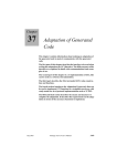
1.17.3.3 General architecture
Reqtify relies on these previously installed files to work as described in the following diagram:
Opens
RTDS
Stores
Checks
modification
RTDS
project
read by
Calls
rtdsRDP2Text
4Reqtify
Generates
Reqtify
RTDS simplified
project file
An RTDS diagram can be opened directly from Reqtify. Reqtify also checks if the RTDS
project file has been modified. If the file has been modified, it calls
rtdsRDP2Text4Reqtify utility that generates a project file understandable by Reqtify.
Real Time Developer Studio V4.1
Page 39
User Manual
1.17.3.4 Usage
It is now possible to add an RTDS project into Reqtify and to set its type to PragmaDev
RTDS as shown below :
Page 40
Real Time Developer Studio V4.1
User Manual
Click Ok and Reqtitfy will display the RTDS project architecture as shown in the example
below :
Real Time Developer Studio V4.1
Page 41
User Manual
Clicking on an element of the RTDS project will open that element in RTDS. If not a valid
component (package or folder) a warning message will ask to select a valid diagram.
1.17.3.5 Format of traceability information
By default the traceability information for all component has the following format :
cover=’<REQUIREMENT_IT_COVER>’ requirement=’<REQUIREMENT_TO_COVER>’
Page 42
Real Time Developer Studio V4.1
User Manual
This can be customized with Reqtify type editor. For example would you like the traceability information to have the format coverage=’<REQUIREMENT_IT_COVER>’ for
the SYSTEM component, right clik on PragmaDev RTDS type and duplicate it :
Real Time Developer Studio V4.1
Page 43
User Manual
Open the reference section of the SYSTEM component named ReferenceSystem to
change the name of the attribute as shown below :
Page 44
Real Time Developer Studio V4.1
User Manual
Before validating this new type, the project editor needs to know that the type of analysis
has changed. To do so select this type of analysis in the project editor and click OK :
1.17.3.6 Example
The following example creates a link from a Word document to an RTDS Project with the
default Reqtify syntax.
Real Time Developer Studio V4.1
Page 45
User Manual
In a Word document, the requirement identifier REQ1 is defined with Requirement_ID
style.
Within RTDS select the element covering the requirement and go to the Element / Traceability information... menu. In the Node traceability information popup window, indicate
which requirement is covered.
Page 46
Real Time Developer Studio V4.1
User Manual
Add both documents in the Reqtify Project Editor with their respective analysis type and
create a coverage link from one document to the other :
Real Time Developer Studio V4.1
Page 47
User Manual
After analysis, Reqtify will show the links in the Graphical View editor :
Page 48
Real Time Developer Studio V4.1
User Manual
2 - Diagram editor
The diagram editor is the window where all types of diagrams may be edited. The editor
window is the same for all types of diagrams, and its basic features are the same. It may
however have a few extra features depending on the type of the displayed diagram.
Diagram editor window
2.1 - Common features
2.1.1 Frame concept
All diagrams have a surrounding frame, containing all the symbols in the diagram. You
can’t put symbols outside that frame. For SDL system and block diagrams, the frame also
represents the external boundary of the agent, and channels may be connected to it.
Real Time Developer Studio V4.1
Page 49
User Manual
2.1.2 Symbol and link properties
Each symbol or link has a property sheet allowing to enter all its features in a guided way.
The actual properties depend on the type of the symbol or link. It may be opened by
selecting a symbol or link and choose "Properties…" in the contextual menu.
The basic property sheet for a symbol is the following:
• The symbol text is the one that normally appears in the text.
• The symbol shortcut text may be used to specify an alternate text to display in the
symbol and to open its "real" text in an external editor. It may be used for symbols with a very long text to avoid taking too much space in the diagram. If this
shortcut text is set, it will appear underlined in the diagram:
Double-clicking on the symbol shortcut text will open the external editor showing the symbol actual text.
• The PR code suffix is available for all symbols but is only meaningful for symbols
declaring a SDL agent. This text will be inserted after the agent declaration in
exported PR files whenever the actual agent is not defined. This is used to keep
Geode-style external references in RTDS diagrams; It should usually be left
empty.
• The colors are the color for the symbol’s text and outline and the color for its
background.
• The symbol description is only used for documentation purposes.
Page 50
Real Time Developer Studio V4.1
User Manual
The default property dialog for a link only includes its color:
Please refer to the paragraphs describing the editors for examples of property sheets for
specific link types.
2.1.3 Moving symbols
The symbols in a diagram may be moved by using the mouse or via the arrow keys: if a
group of symbols is selected, pressing the arrow keys will move the symbols by one grid
cell. Pressing the arrow keys while maintaining the Control key pressed will move the
symbols by one point.
2.1.4 Modifying links
There are two ways of modifying existing links in the diagram editor:
• For broken links, the segments may be moved by using the handle appearing in
the segment middle:
press on handle, then drag and release
If needed, segments will be automatically created or deleted:
• For all links, diamond-shaped handles at both ends allow to change the symbol
to which the link connects:
press on handle, then drag and release
Real Time Developer Studio V4.1
Page 51
User Manual
2.1.5 Button and tool bars
As seen in the screen shot above, the diagram editor window has several button bars and
tool bars. The button bars give access to all usual operations. The tool bars are at the left
of the window and are separated in 3 parts:
• The top tool bar gives access to the general operations on the contents of the diagram. It’s usually restricted to the selection tool, but MSC diagrams have a few
extra tools (see “Specific tools” on page 70).
• The middle tool bar is the symbols tool bar. It allows to insert new symbols in the
diagram. This insertion is made by clicking on the button corresponding to the
symbol you want to insert, then clicking within the diagram’s frame where you
want to insert the symbol.
• The bottom tool bar is the links tool bar. It allows to insert new links between
symbols within the diagram. There is a button for each link type allowed in the
diagram. Make sure you select the right type for the symbols you want to link, or
the insertion may be refused.
The link insertion is made by clicking on the button corresponding to the link
type you want to insert, then pressing the mouse button over the first symbol and
dragging to the other symbol. If you want to manually indicate a path between
the two symbols, shift-click on the first symbol, then shift-click on each corner
for the link. Holding the shift key allows to restrict the move to horizontal or vertical lines. For example:
click with
shift pressed
move with shift pressed
click with
shift pressed
move with shift pressed
move
click
click
Above the toolbars is a tiny lock icon that looks like this:
. When this icon is not active,
the button inserts a single symbol or link: once one symbol or link has been inserted, the
editor returns to selection mode. Clicking once on the icon makes it active. After that, any
insertion button will be "sticky": any number of symbols or links may be inserted in a
row. To go back to "non-sticky" mode, press the lock icon again or select the selection
tool.
The button and tool bars have a common aspect and behavior: Both have a header looking this:
Page 52
. It is at the left for button bars and at the top for tool bars. By clicking on this
Real Time Developer Studio V4.1
User Manual
header and dragging it away, the bar can be detached from its parent window and displayed in its own window.
Symbol tool bar for blocks
To put the tool bar back in its parent window, just close the tool bar window.
2.1.6 Partitions
Large diagrams can be split into partitions. A partition is a set of pages that may contain
any number of symbols and links. Partitions may be added, deleted and printed via the
"Diagram" menu.
Navigating through partitions can be done by using the left-most toolbar in a diagram
window or with the partition browser, displayed at the right of the diagram. If several
browsers are available, the partition browser can be selected via the "Part." tab at the top
of the browsers:
Notes:
• A partition can only be deleted if it doesn’t contain any symbol or link.
• Partitions are not available in MSC diagrams.
Real Time Developer Studio V4.1
Page 53
User Manual
2.1.7 Page setup
To ensure a WYSIWYG behavior, all partitions in a diagram include a page setup that will
be the one used when printing it. This page setup may be edited via the "Partition page
setup..." item in the "Diagram" menu in diagram editors. The following dialog appears:
The fields "Paper", "Landscape", "Page width (cm)" and "Page height (cm)" are used to
specify the paper size. The "Margins" are automatically removed from the usable area for
the partition and when printing. If the "Add page footer" option is checked, a footer will
be displayed on each printed page, containing the name of the printed file and the page
number. The height of this footer is also removed from the usable area for the diagram.
This usable area is displayed with its dimensions in the right part of the dialog.
The field "Number of pages" one is used to specify the number of rows and columns of
pages in the diagram.
A default page setup can be configured in the project manager (menu "File", "Page
setup..."). Clicking the button "Get project defaults" in any page setup dialog will select
this default page setup.
There is a shortcut to add a row or column of pages in diagrams: along each side of the
edge pages, the following buttons appear:
These buttons will add a page column or row to the diagram respectively.
2.1.8 Publications
It is possible to attach to any diagram a set of publications. A publication is a set of symbols that will be exported as one or several external image file(s). These publications are
Page 54
Real Time Developer Studio V4.1
User Manual
dynamic: the set of exported symbols is remembered and you can re-export them at any
time, or ask to have them exported automatically when you save the diagram (see paragraph about diagram preferences in “PR (Phrasal Representation) and CIF (Common
Interchange Format) files are ITU-T standards to exchange SDL models from one tool to
another. RTDS allows to import a file in SDL PR/CIF format to a RTDS SDL project file.
This is done via the "Import PR/CIF file…" item in the "Project" menu. The import configuration is made via a wizard; The panels in this wizard are described in the following
paragraphs.” on page 15).
These publications can be used by importing them in any word processing software that
has an "insert with link" or "import by reference" function. This function allows to insert
a file into the current document, but keeps a reference to the inserted file so that any
modification to the inserted file will be reflected automatically in the document. Since
RTDS will update the publications after each diagram modification, it will ensure that
the contents of the document importing them will always be up to date.
There are currently 5 types of publications:
• Symbol publications will export a set of given symbols;
• Transition publications will export all symbols in a given transition, identified by
its state and message input or continuous signal;
• State publications will export all symbols in all transitions attached to a given
state symbol;
• Partition publication will export a whole partition;
• Diagram publications will export the whole diagram.
These publications are available via the entries "Export/publish …" in the "Export" menu
in diagram editors. All these entries open the following dialog:
The dialog allows to set:
• The name for the publication if any. When doing a simple export, this field does
not need to be filled.
• The type for the exported image(s): PNG, JPEG, EPS for Encapsulated Postscript
or CGM. Another type named ’Doc’ is also available. It should be used for publications that are only used in RTDS documents. These kind of publications don’t
actually export anything until the document they’re included in is itself exported
to a given format. For more information, see “Document editor” on page 91.
Real Time Developer Studio V4.1
Page 55
User Manual
• Whether the exported image(s) should be wrapped in a HTML file. This should
be used if the publication consists in several images or pages. Importing the
HTML file in a word processing software allows to import the whole set of
images in one operation, and to keep it up to date even if the grows or shrinks
afterwards. Note that this option should only be used for PNG or JPEG images,
as browsers usually can’t display Encapsulated Postscript or CGM images.
• For partition and diagram publications, each exported image contain by default a
whole partition. Checking the "Split images into pages" option allows to export
an image per printed page in the diagram or partition.
• The file name for the exported image; please note a suffix can be added to this
name if the publication exports several images.
• Whether the file name for the publication should be remembered as an absolute
pathname, or relative the the diagram file name.
• The zoom factor applied before exporting.
• Whether the exported images should be remembered in a publication or not. If
the option is not checked, the export will be done one time, but not kept up to
date with the diagram.
Page 56
Real Time Developer Studio V4.1
User Manual
The ’Texts >>>’ button allows to associate texts with the publication. Clicking on it
changes the dialog to show two text editors:
These editors are used to create or edit the styled texts that will automatically appear
before and after the publication image when included in a document. For more information, see “Styled text editor” on page 101.
The list in the left part of the dialog contains the names for the already existing publications. Clicking on one of the names will display the attributes for the publication in the
dialog as in the "Manage publications" dialog. It is possible to go back to the current one
by clicking the ’<<New>>’ entry, which is always the first in the list. The actual export is
done by clicking ’Apply’ or ’OK’.
Real Time Developer Studio V4.1
Page 57
User Manual
The last item in the "Export" menu is named "Manage publications..." and opens the
same dialog as above, except it won’t show a ’<<New>>’ entry:
The zone in the dialog’s left part lists the names for all publications in the current diagram. Clicking on one of the names will display the publication attributes in the right
part, and allows to change some of them. The ’Show’ button will display the exported part
of the diagram; The ’Export’ button allows to explicitely update an existing publication.
Notes:
• When saving a diagram having publication, a dialog may appear asking whether
to update the publications. This behavior is controlled by the "Update publication" option in the diagram preferences (see “Diagram preferences” on page 26).
• On Windows, the selected symbols may also be directly copied to the Windows
clipboard by using the item "Copy as bitmap" in the "Edit" menu (shortcut: ShiftCtrl-C). This feature is not available on Unix platforms.
• The publications may also be used in documents written using a markup language like SGML, XML or HTML. For example, with HTML, images may simply
be imported via the tag <img src=""> without giving any dimension for the
image so that they will always be read from the image file.
• Some word processors (e.g. FrameMaker) remember the size you gave to any
imported graphics, even if these were imported by reference. RTDS publications
still work with these, but you may end up with distorted graphics in the final document if the size of a publications changes.
Page 58
Real Time Developer Studio V4.1
User Manual
2.2 - SDL editor features
2.2.1 Link properties
The following link types have specific property dialogs:
• Channels in system or block diagrams have the following property dialog:
The dialog allows to modify the channel name and for either end of the channel,
the received signals and the gate name if available. The gate name is available
only if the symbol is a block or process class instance.
• Decision and transition option links in process or procedure diagrams have the
following property dialog:
The only additional information is the condition on the link.
2.2.2 Creating and opening components
Some diagrams may contain symbols that are defined via another diagram. E.g., block
and system diagrams may contain process and block symbols that will be described via
Real Time Developer Studio V4.1
Page 59
User Manual
process and block diagrams. These diagrams are displayed as children of the first diagram in the project tree in the main window (see “Project” on page 7).
The definition diagrams for symbols are not added to the project as described in the
paragraph “Adding components to the system” on page 11, but as follows:
• Select the symbol for which you want to create the definition diagram;
• Select the item "Open definition..." in the contextual menu or the "References"
menu or double-click on any part of the symbol, except its text (hint: the cursor
should be an arrow, not a text caret);
• If the definition diagram for the selected symbol doesn’t exist, the project manager will pop up and ask if you want to create it. If you answer "OK", the "Add
component" dialog described in “Adding components to the system” on page 11
will allow you to enter the features for the new node.
• The definition diagram will then appear in the current window if it’s reusable, or
in another one if it’s not.
You may open definition diagrams for the following symbol types:
• Block and process symbols in block or system diagrams, including instances of
block or process types;
• Block types and process types in block or system types diagrams;
• Process creation symbols in process or procedure diagrams;
• Procedure declarations and procedure call symbols;
• Composite state declarations or usage symbols;
• Service symbols in composite state diagrams;
• Declaration text boxes containing an "INHERITS" line in process types;
• MSC references in MSC and HMSC diagrams.
Automatic creation of definition diagrams is also supported for all these symbols, except
the process creation symbol, where the created process may be anywhere in the system.
Please note:
• Renaming or deleting a symbol having a definition diagram will rename or delete
the node in the project tree. The deletion will display a confirmation dialog, asking whether the diagram file should be deleted.
• The reverse is not true: deleting or renaming a node in the project manager will
not update the corresponding diagram. For example, if the name for a process
diagram node is changed in the project manager, trying to open this process
from its parent diagram will fail and display the dialog asking if the process diagram must be created.
2.2.3 Automatic insertion
This feature allows to automatically create a symbol just below the current symbol with a
link between the two. It is available in process, process type, procedure, macro and
HMSC diagrams. It allows to easily create a vertical flow of symbols without having to
create all symbols and links manually.
Page 60
Real Time Developer Studio V4.1
User Manual
The automatic insertion is done by double-clicking on the symbol tool for the symbol you
want to insert:
Manually inserted "Start" symbol
Make sure it is selected
Double-click on "State" symbol;
"State" symbol automatically inserted
below current symbol.
(new state)
Double-click on "Signal input" symbol;
Idle
"Signal input" symbol is automatically inserted
below current symbol.
<signal>(...)
The automatic insertion will also choose automatically the "best" link type for linking the
two symbols:
printf("Hello, world!\n");
Automatic insertion of a condition after a task block
<expr>
x == 0
<value>
Automatic insertion of a task block after a condition
<actions>
Real Time Developer Studio V4.1
Page 61
User Manual
The position of the auto-inserted symbol is also computed to avoid symbol overlap:
Idle
Idle
signal1
signal1
<signal>(...)
x == 0
x == 0
true
true
<value>
y == 0
y == 0
<actions>
true
false
true
false
Idle
Idle
Idle
Idle
Auto-insertion is also provided for comment and text extension symbols. These symbols
will be inserted at the right of the selected one:
printf("Hello, world!\n");
printf("Hello, world!\n");
(comment)
2.2.4 Automatic transition selection
Sometimes, a symbol must be inserted in the middle of an existing transition. This case is
not handled by the autoamtic insertion described above, as this feature won’t move existing symbols. To ease such an insertion, RTDS allows to automatically select all symbols
Page 62
Real Time Developer Studio V4.1
User Manual
following a given one in a transition. This is done via the "Edit" or contextual menus,
item "Select to end":
Idle
signal1
x == 0
true
false
y == 0
<actions>
true
false
Idle
Idle
Idle
Idle
signal1
x == 0
true
false
y == 0
<actions>
true
false
Idle
Idle
Idle
This allows to move all symbols following a given one to make space for a new one
inserted before it.
Real Time Developer Studio V4.1
Page 63
User Manual
Once this is done, the new symbol can be inserted in the middle of an existing link by
selecting the link and double-clicking on the symbol tool, as for auto-insertion below
symbols:
x == 0
x == 0
true
true
<actions>
y == 0
y == 0
true
false
true
false
Idle
Idle
Idle
Idle
2.2.5 "View" / "Go to" menu and state / message browser
The process and process type editors include a feature allowing you to go directly to a
given signal input in a given state. This feature is available:
• Via the "Go to" sub-menu in the "View" menu. This sub-menu includes one submenu per state defined in the process or process type. The sub-menu for a state
includes an item for each signal input defined for this state. Selecting one of
these items displays the corresponding symbol.
• Via the state / message browser that may appear in the right part of the editor
window. This browser shows each state in the process, followed by each input
message accepted in this state. Clicking on the message name displays the corresponding symbol in the diagram.
2.2.6 State and connector usage
The "View" / "Go to" menu and the state / message browser show the entry states and
messages in transitions. RTDS also allows to find where a given state is used as a next
state. This is also available for connectors: for a given "in" connector, it is possible to
show where it is used as an "out" connector. This is done by selecting the state or "in"
Page 64
Real Time Developer Studio V4.1
User Manual
connector symbol and selecting "Show usage…" in the "Edit" or contextual menu. The
following window appears, showing all symbols using the given state or connector:
Each line continas a diagram file name, a symbol identifier and the text for this symbol.
Double-clicking on a line (or selecting it and pressing the "Show" button) will open the
given diagram and display the symbol.
Note that for process classes, the symbols using the state or connector in the super-class
or all sub-classes are also displayed.
2.2.7 Diagram diff
RTDS allows to make a graphical diff of two diagrams within a project, or of a diagram
within the project with an external diagram. This feature is available in the diagram editor via the "Make diff on diagram…" item in the "Diagram" menu, or in the project manager in the "Make diff on diagram…" item in the "Element" menu.
The diff is configured via the following dialog:
The first diagram is always taken in the current project. The second diagram can either
be chosen among the current project compatible diagrams in the drop-down menu, or
read from an external file by using the "Browse…" button. If the "Logical diff only"
option is checked, only logical differences between the two diagrams will be reported. If
this option is not checked, differences may be reported for elements that appear in both
diagrams if the symbol defining them have moved or has been resized.
Real Time Developer Studio V4.1
Page 65
User Manual
The results for the diff is displayed as follows:
Both compared diagrams are opened and automatically placed side by side on the screen.
The different parts are identified by colors in the editors (NB: the colors set for symbols
are ignored when in diff mode).
The window below the editors allow to navigate through the differences. This window has
3 possibles layouts:
• The "Tiny" layout is the one shown above:
The only thing it allows is to navigate through the differences and to recompute
the diff (see below).
• The "Brief" layout is as follows:
The differences are grouped by transition. For each difference, only the number
of impatced elements is displayed. When navigating through differences, the
currently displayed one is identified by the green borders on each side. Clicking
Page 66
Real Time Developer Studio V4.1
User Manual
on a difference will make it current and display the corresponding elements in
the diagrams.
• The "Detailed" layout is as follows:
The differences are grouped and shown as in the "Brief" layout, but a full description is given for each difference.
If one of the diagrams is modified while showing differences, the differences can be
recomputed using the "Recompute diff." button.
2.2.8 Automatic environment process creation
This feature is only available in system, block and block class diagrams. It allows the
automatic creation of an environment process from a MSC or a HMSC diagram.
The new process’s state automaton is extracted from the sequence of sent and received
messages for a given lifeline in a MSC or the set of MSCs referenced by a HMSC. For
example, the following MSC:
Real Time Developer Studio V4.1
Page 67
User Manual
will generate the following state automaton:
This function is called as follows:
• In the block or system diagram, select the item "Create RTDS_Env from" /
"MSC…" or "HMSC…". One of the following dialogs appear:
• For a creation from a MSC:
• For a creation from a HMSC:
• Select the source diagram and select or type the name of the source lifeline in the
dialog, then press OK. The cursor turns into a regular symbol insertion icon.
• Click on the desired location for the new environment process.
• The new process symbol with the name "RTDS_Env" is then inserted with the
corresponding channels and the process appears in the project tree.
Notes:
• This feature is only available for SDL-RT diagrams.
Page 68
Real Time Developer Studio V4.1
User Manual
• When creating from a HSMC diagram, the source diagram cannot contain parallel sequences, or the creation will fail. Alternatives are allowed.
• When creating from a HSMC, the behavior of the created process may be ambiguous. For example, the source HMSC with the MSCs it references may look like
follows:
In this case, there’s no way to know if the created process should send m2 or m3
after receiving m1. So the created process will look like follows:
Both options have been made available through two connectors. The default
behavior is to send m2, but you can change it by changing the name for the connector after the message input symbol.
If several ambiguities are found, several connectors are generated. The name for
the connector is always "Mx_y", where x identifies the ambiguity and y identifies
one of the possible choices. So an "out" connector "Mx_y" may be connected to
any "in" connector with the same x.
Real Time Developer Studio V4.1
Page 69
User Manual
2.3 - MSC editor
The MSC editor is mainly the same as the editor for other SDL diagrams. However, there
is a few extra features that are described in the following paragraphs.
2.3.1 Specific tools
The top tool bar for MSC diagrams has two more MSC specific tools:
•
allows to select a time range within the diagram: all events occurring to all
lifelines between a given start time and a given end time may be selected, copied,
cut and/or pasted somewhere else in the diagram. While this tool is selected,
horizontal guidelines follow the mouse cursor to indicate precisely what will be
selected.
To select a time range, press the mouse button at the desired start time and drag
to the desired end time.
Once a time range has been copied or cut, pasting is done by clicking at the
desired insertion time. The paste operation also displays a horizontal guideline,
and may be cancelled by hitting the "Esc" key or by selecting the regular selection
tool.
Please note that it’s impossible to select a time range in a diagram and to paste it
in another.
•
allows to insert empty space in the diagram: press the mouse button at the
desired insertion position and drag. When releasing the button, and if it’s possible, a space having the length between the start and end position will be inserted
in the diagram.
2.3.2 Manipulating components in lifelines
To the difference of all other symbols, lifeline are composite symbols: they may include
several components like segments, timers or time constraints. They may also die before
Page 70
Real Time Developer Studio V4.1
User Manual
the end of the diagram or survive it. All these features are managed via the contextual
menu in the MSC editor:
When a lifeline is selected, the items in this menu have the following action:
• "Lifeline dies/survives": toggles the instance tail / instance stop ending for the
lifeline:
• "Add to lifeline": adds to the lifeline a segment, an action symbol, a timer or a
time constraint. After selecting an item in the sub-menu, press the mouse button
at the desired start position of the segment, action symbol, timer or time constraint in the lifeline, and drag to its end position (if applicable). To cancel the
insertion, hit the "Esc" key or select the selection tool.
• "[Un]span lifeline(s)" attaches or detaches a spanning symbol from a set of lifelines. Spanning symbols are conditions or MSC references, which are attached to
one or several lifelines: if the lifelines are moved, the size of the symbol is
updated so that the lifelines are always spanned by the symbol.
This menu item only works when a spanning symbol and one or several lifelines
are selected:
• If the selected lifelines are not spanned by the symbol, they’re added to the set
of spanned lifelines;
Real Time Developer Studio V4.1
Page 71
User Manual
• If the selected lifelines are already spanned by the symbol, they’re removed
from the set of spanned lifelines.
A dialog will inform you about the performed operation.
Please note: there is no visual information on the diagram about lifelines
spanned by symbols. The lifelines are always behind spanning symbols, even if
they’re not spanned.
The "Delete" menu item also has a special meaning if a lifeline item such as a component,
timer or time constraint is selected. In this case, only the item is deleted, not the entire
lifeline. A confirmation dialog will always specify what is deleted. Note that it is impossible to copy or cut a single item. To remind you of this, when a lifeline item is selected, the
whole lifeline will still appear as selected, but with white handles instead of black ones.
2.3.3 Message parameters display
A specific sub-menu in the "View" menu controls the message parameter visibility:
• A visibility set to "Full" displays the full text for the message parameters as it is
recorded in the diagram file. The parameters for structured messages are then
displayed in the format described in paragraph “Sending SDL messages to the
running system” on page 209. This can make the diagram quite difficult to read,
as this format is quite complex;
• A visibility set to "Abbreviated" still displays completely parameters for nonstructured messages, but only displays the first level of parameter values in
structured parameters. An example of this visibility can be seen below;
• A visibility set to "None" hides all message parameters.
This visibility setting is stored with the diagram. Please note it is only possible to modify
the text for the message parameters if the visibility is set to Full.
When the visibility is set to "None" or "Abbreviated", structured messages are indicated
by a "»" before their name. Their parameters may be displayed by clicking on the message link: a panel then appears in the right part of the editor window displaying the
parameters as a tree. For example, for a message with the full text:
mParams(|{param1|=1.7|,param2|=0x80533D8|:|{len|=6|,buffer|=
0x804EEFA|:zz|}|})
Page 72
Real Time Developer Studio V4.1
User Manual
the display with parameter visibility set to "Abbreviated" and the link selected is:
Other information is also displayed in the panel, such as the sener and receiver process
and their states before and after they sent / received the message.
Real Time Developer Studio V4.1
Page 73
User Manual
2.3.4 MSC Diff
This command allows to show the differences between two MSC diagrams.
2.3.4.1 Running the diff
It can be launched from the MSC editor’s "Diagram" menu, or from the project manager’s contextual menu or "Element" menu when an MSC diagram is selected.
A dialog window pops up:
Here can be selected the two MSC diagrams from the current project or from the file system. Filters can also be applied on the result of the MSC diff. Symbol types can be:
Page 74
Real Time Developer Studio V4.1
User Manual
• Removed from the resulting diagram ("Hide"), or
• Viewed but not checked in the diff ("Show"), or
• Viewed and checked in the diff ("Show & diff").
In this case a symbol appearing only in one of the two diagrams will be displayed
with a specific color.
2.3.4.2 Result analysis
The resulting MSC identifies the lifelines (processes) between the two diagrams by their
name and if necessary (if there are several processes with the same name), by the
sequence of their events. If two lifelines in the two diagrams represent the same process
but do not have the same name, they will not match.
Note the MSC diff searches for the difference in the sequence of events on the lifelines.
The elapsed time between two events on the resulting diagram is not significant.
2.3.4.3 Example
The diff is made on the following two MSC diagrams:
Real Time Developer Studio V4.1
Page 75
User Manual
First MSC diagram in diff
Page 76
Real Time Developer Studio V4.1
User Manual
Second MSC diagram in diff
The differences are quite clear:
• The "slave" process takes the semaphore "Sem" in the first diagram, but not in
the second.
• The processes "master" and "sonproc" exchange messages "stillAlive", "ack" and
"die" in the second diagram, but not in the first.
• Process "sonproc" dies in the second diagram, but not in the first.
Real Time Developer Studio V4.1
Page 77
User Manual
Here is the result of the diff:
The differences are identified by colors: in the diff diagram, the events specific to the first
diagram are represented in red, and the events specific to the second diagram are represented in blue.
Page 78
Real Time Developer Studio V4.1
User Manual
2.3.5 Filtering
Large MSCs might get very difficult to read; in that case the MSC filtering feature can be
used to remove useless information from the diagram.
In the MSC diagram editor go to the Diagram / Filter Diagram... menu:
Real Time Developer Studio V4.1
Page 79
User Manual
The MSC filter configuration window pops up:
Select the information to be filtered out of the MSC and click OK.
A new MSC is created with the selected elements filtered out:
Page 80
Real Time Developer Studio V4.1
User Manual
Please note the resulting MSC might not have the same layout as the original MSC. This
is because the original MSC is translated to a list of a MSC events that is filtered. The
resulting MSC is built out of the sequence of left events. So for example the vertical space
between events is always the same.
2.3.6 MSC PR import
It is possible to import MSCs stored in PR (Phrasal Representation) textual format as
defined in ITU-T Z.120 recommandation. The MSC must be event oriented (as opposed
to instance oriented) and the CIF information if any will be ignored.
A Z.120 MSC PR example
Real Time Developer Studio V4.1
Page 81
User Manual
In the Project Manager, go to the File / Import MSC-PR file... menu and select the file to
import.
Import MSC menu
Page 82
Real Time Developer Studio V4.1
User Manual
The resulting MSC will be added to the project.
Imported MSC
Real Time Developer Studio V4.1
Page 83
User Manual
2.3.7 MSC PR export
It is possible to export MSCs to an event oriented Z.120 MSC PR file. In the MSC diagram
to export, go to the Diagram / Export as PR... menu.
Export as PR menu
Page 84
Real Time Developer Studio V4.1
User Manual
The results of the export is as follows:
Export MSC PR example
Real Time Developer Studio V4.1
Page 85
User Manual
2.4 - UML diagrams
2.4.1 Symbol properties
For symbols that may show attributes and/or operations (class symbols in class diagrams, nodes and components in deployment diagram), a specific property sheet is available:
This property sheet is divided into 3 or 4 tabs depending on the selected symbol. These
tabs are described in the following paragraphs.
2.4.1.1 "Text" tab
This tab is shown above. It contains the standard symbol colors and the textual representations for all texts associated to the selected symbol: class header, attributes and operations. The operations do not appear for nodes or components since they are meaningless
for these symbols. Two check-boxes are also available, allowing to hide the attribute and
operation parts in the displayed symbol respectively.
Page 86
Real Time Developer Studio V4.1
User Manual
2.4.1.2 "Class" tab
This tab is the second one in the dialog:
It contains the class’s stereotype, package name, name, property string and description.
These will be included in the class header as:
<<stereotype>> package-name::class-name {property-string}
Real Time Developer Studio V4.1
Page 87
User Manual
2.4.1.3 "Attributes" tab
This tab is the third in the dialog:
The list in the left part allows to manage the attributes. Attributes may be created ("+"
button), deleted ("-" button) or re-ordered (arrow buttons).
The fields in the right part allows to modify the attribute selected in the list. The text for
the attribute will be:
visibility name[multiplicity]
: type = default-value {property-string}
The visibility is rendered as the standard UML character (’+’ for public, ’#’ for protected
and ’-’ for private). The multiplicity, type, default value and property string are included
only if they are not empty.
Any modified attribute will be automatically updated in the attributes text in the "Text"
tab.
Page 88
Real Time Developer Studio V4.1
User Manual
2.4.1.4 "Operations" tab
This tab is the fourth in the dialog:
This tab is not available for nodes or components, as these do not have any operations.
The list in the left part allow to manage the operations. The buttons are the same as for
the attributes (see above).
The fields in the right part allow to modify the operation selected in the list. The text for
the operation will be:
visibility name(parameters)
: return-type {property-string}
where parameters is a comma-separated list of parameters formatted as follows:
direction name
: type = default-value
The visibility is rendered as the standard UML character (’+’ for public, ’#’ for protected
and ’-’ for private). The return type and property string for the operation and the type
and default value for the parameters are included only if they are not empty.
Constructors and destructor are defined with the UML stereotypes: <<create>> and
<<delete>>.
Any modified operation will be automatically updated in the operations text in the "Text"
tab.
Real Time Developer Studio V4.1
Page 89
User Manual
2.4.2 Link properties
Specific properties for association, aggregation and composition links may be modified
via their property sheet:
In addition to the link name and color, the read direction for the link may be modified: if
the "Reverse read dir." check-box is checked, the link should be read from the "To" class
symbol to the "From" class symbol.
For both class symbols at the ends of the link, the dialog allows to modify the cardinality
if available, the role name and the navigability. The rules for the navigability are those
defined by UML:
• If the navigability is the same for both ends of the link (either on or off), each
class will have an attribute representing the association.
• If the navigability is on only for the "From" (rep. "To") class symbol, only the
"To" (resp. "From") class symbol will have an attribute for the association.
2.4.3 Access to generated C++ files
Double-clicking on a class symbol in a class diagram opens the generated C++ file for the
class if there is one. Please note the file is not generated if it does not yet exist.
Page 90
Real Time Developer Studio V4.1
User Manual
3 - Document editor
RTDS’s way of handling documents is a bit different from what one can find in word processors. In a word processor, a document is just a set of paragraphs, usually having a
style - named or not -, and each paragraph typically contains ranges of characters,
optionally styled, and/or images. There is sometimes a notion of document structure in
terms of chapters, containing sub-chapters, containing sections, and so on, but this
structure is deduced from the paragraphs.
On the contrary, RTDS mainly uses the structure: a document is a set of chapters, subchapters, and so on, and the styles applied to the paragraphs are deduced from the structure. More precisely:
• A document is defined as a tree of sections. The top-level sections are the chapters; the ones under the chapters are the sub-chapters, and so on…
• Each section also has a section header, which is the text and images that will
appear in the section before its sub-sections.
Section with level 1
Section with level 2
1. INTRODUCTION
1.1. Object of the document
This document is about …
1.2. Scope
This document applies to …
2. USE CASES
2.1. Diagrams
…
2.2. Descriptions
2.2.1. Edit a SDL diagram
…
Header for section 1.1
Section with level 2
Header for section 1.1
Section with level 1
…
Section with level 3
A section header is composed of header items, which can be:
• Text items: these items just contain styled text.
• Publication items: these items are references to publications in diagrams, as
described in “Publications” on page 54. Such a header item will automatically
include in the document:
• The text before the publication if any;
• The part of the diagram that is exported via the publication;
• The text after the publication if any.
• Table items: these items contains a table, each of the table cells being a text item.
• External picture items: these items reference an image in a PNG file.
• External file items: these items just include the contents of an external file in the
document, all text having a given style.
This allows to document the diagrams "on the fly" when the need arises by creating a
publication and entering the texts before and after it. When the final document is written, it will just gather the parts already documented via publications, maybe with some
additional explanation texts in text, external picture or table header items.
Real Time Developer Studio V4.1
Page 91
User Manual
A fully documented system is available in the example files delivered with RTDS. It can
be found under RTDS installation directory ($RTDS_HOME), under examples/SDL/
AccessControl.
Here is a typical view of the document editor:
The left part of the window shows the section tree for the document, and the right part
shows a text field allowing to change the selected section title and the list of its header
items.
Sections can be added or removed from the section tree by using the "Section" menu, or
the contextual menu in the section tree (right-click). The section tree can be rearranged
via drag and drop.
Existing header items may be rearranged via the arrow buttons in the right-bottom corner of the window, or deleted via the ’-’ button. Header items can also be copied, cut and
pasted from section to section, or even from document to document.
Page 92
Real Time Developer Studio V4.1
User Manual
New header items can be added by selecting "New header item…" in the "Section" menu,
or by clicking the ’+’ button in the lower part of the window. This opens the following dialog:
The upper zone allows to choose the type of header item to insert - text, publication,
table, external image or external text file - and all required information for the header
item:
• The parent diagram and the publication name for publication items. Note that
only publications for currently opened diagrams are shown in the dialog, so the
parent diagram for the publication to insert has to be opened before trying to add
the header item.
• The initial number of rows and columns in table items.
• For external picture items, the file name for the referenced PNG image file and
whether its path should be remembered as an absolute or a relative path from
the document file’s parent directory.
• For external text file items, the name of the file to include and the paragraph
style to use for its text.
The lower zone in the dialog allows to specify where the new item will appear.
Once created, a text header item will appear like this:
The text in the item is the beginning of the text actually entered in the item.
Real Time Developer Studio V4.1
Page 93
User Manual
Publication header items will appear like this:
The first line of text is the diagram file name, and the second one is the publication name.
Table items will appear like this:
The first line includes the first table header line if any and the second one gives the table
size.
External picture items will appear like this:
The first line is the full path of the referenced PNG file and the second line indicates if the
reference is absolute or relative.
From the document editor window, it is also possible to export a document to a format
that a word processor can handle. This is in fact the only way to get a form of the document that can be displayed or printed. The formats available today are:
• RTF, which can be used with all the major word processors;
• OpenDocument format, which is an ISO-standard for text documents, mainly
used by OpenOffice.org and other open-source word processors;
• SGML; this format is for advanced users and won’t be described further in this
document. Please refer to the corresponding section in the reference manual for
further details.
To be able to export a document in these formats, RTDS needs to attach presentation
attributes to the texts in the document. This is done via documentation display and
export options, which are displayed in the following paragraphs.
3.1 - Documentation display options
The documentation display options have two main objectives:
• Define what styles are available in publication texts and document section
header text items;
• How these styles will be displayed on screen in the editors.
There are two types of styles:
• Paragraph styles define the appearance for whole paragraphs. This concept is the
same as the usual styles found in word processors. Typical display options for
paragraphs include the font for the paragraph text, its margins, its alignment,
and so on…
• Character styles define the appearance for range of characters within paragraphs. Display options for these styles are just a font (with its family, its size and
its style) and a color.
Page 94
Real Time Developer Studio V4.1
User Manual
Documentation display options are defined in a project, so that all styles will be available
in all diagrams and all documents contained in the project. Setting these display options
is done in the project manager window via the "File" menu, item "Documentation display
options…". The following dialog appears:
The first tab in the dialog allows to define character styles. Clicking on the "+" button
under the list creates a new style by copying the selected one; clicking the "-" button
deletes the selected style. The right part of the dialog allows to change the style name and
to define the font and color for the characters with this style.
The second tab in the dialog allows to define the paragraph styles and looks like this:
Styles are created and deleted just as character styles. The style options are:
• Its name;
• Its type. A paragraph style may be either a normal paragraph in a text body, a list
header, a paragraph inside a list or a style for section headings.
• Its level. This option is not used for normal paragraphs in a text body. For the
other types:
• For section headings, the level is the section level;
Real Time Developer Studio V4.1
Page 95
User Manual
•
•
•
•
•
• For list headers or paragraphs in lists, the level is the list level.
Please note that RTDS is more strict than other word processors: it won’t let you
create a list with a level set to 3 after a normal paragraph, or directly inside a list
with level 1.
Its left margin. This is the distance in centimeters from the left border of the text
editor to the position from which the text starts.
Its first indent. It is the distance in centimeters from the left margin to the position from which the text of the paragraph’s first line starts. For normal paragraphs, it is usually 0. For list headers, it is usually negative to add some space
for the bullet or list number. It may also be used for section headings to set a
fixed width for the section number.
The font for its characters, including the font family, its size and its style (bold,
italic, underlined).
The alignment for the paragraph: left-aligned, right-aligned or centered. Please
note that full justification is not available in the editors. It is only available in
export styles (see “Documentation export options” on page 96).
The color for the paragraph’s text.
NB: Styles for section heading paragraphs must be defined here, but they will not be
directly available in editors, since the section headings should be defined via the document structure, and not directly within texts. The display options defined for these styles
are also not significant today, as the document sections are never displayed as styled
texts.
3.2 - Documentation export options
Display styles are only used when displaying styled texts on screen. When exporting a
document to a format usable in a word processor, more options are available. These
options are defined via the documentation export styles. The export styles are also
attached to a project.
Page 96
Real Time Developer Studio V4.1
User Manual
Defining export styles is done in the project manager by selecting the "Documentation
export styles…" in the "File" menu. This opens the following dialog:
The upper zone in the dialog defines some options that are not dependant on the export
format:
• The minimum image reduction factor defines how images built from diagram
publications will be sized when included in the exported document. The default
is to adapt the image size to the width and/or height of the page. This option
allows to specify that images should always be reduced by this factor before
doing any other adaptation.
• The next two tables allows to automatically set up an index in the exported document:
• The left-most table defines what are the concepts that will automatically be
included in the document index. These index entries will be figured out automatically by RTDS each time an image from a diagram publication is
exported. If this image includes any concept checked in this list, an index
entry will be automatically set up, with the concept name as its text, referring
this image in the document. Available concepts are packages, agents, procedures, messages and message lists, passive classes, class attributes, class operations and semaphores (in SDL-RT projects).
Real Time Developer Studio V4.1
Page 97
User Manual
• The right-most table defines a set of character styles that will also automatically be included in the document index. The text for the entry will be the
whole text with this style. This allows to explicitely define index entries in any
text.
NB:
• This is actually the only way to define "custom" index entries today.
• This may lead to duplicate existing character styles to be able to define the index.
For example, a character style can be defined for bits of code in a document, with
typically a fixed-width font. If class, attribute or operation names are included in
the text, and if the index should reference these names, it is possible to duplicate
the code style to a style named indexed_code for example, and to use
indexed_code for all these names.
Below these two tables are options to create "extended" index entries. These
entries will not only include the text for the entry, but also a short description of
what it is (concept name for concepts, style name for character styles).
The lower zone in the dialog defines the options that depend on the format used for
export, arranged in tabs:
• The first tab shows the export options for the character styles:
The list in the left part shows the available character styles, as defined in the documentation display options. Please note that you cannot add, remove or rename
styles here; they have to be removed from the display options (see “Documentation display options” on page 94).
The right part allows to change the actual export style for the character style,
which is only the font and the color.
Page 98
Real Time Developer Studio V4.1
User Manual
• The second tab shows the export options for the paragraph styles:
As for character styles, the list in the right part shows the list of available paragraph styles. Again, the available styles are defined via the documentation display options and cannot be added, removed or renamed here (see
“Documentation display options” on page 94).
The right part shows the export options for the paragraph style. As there are
many options, they are organized into groups:
• The "Text" group (shown above) includes the options for the text itself, including its font, its color, and the heading to automatically include in the paragraph if any. This heading is only available in section heading and list header
paragraphs:
• The heading width should be set only if the heading has a fixed width, typically for
list headers.
• The heading character style may be used to give a different style to the heading
text. This may be typically used for list bullets.
• The heading text may contain markers for the section or list number in many formats, and the number for the parent section or list. These markers don’t need to be
explicitely typed and can be entered by using the menu available via the
ton:
Real Time Developer Studio V4.1
but-
Page 99
User Manual
• The "Layout" group includes the options for the text layout on the page:
These options are quite usual:
• alignment (including the fully justified option),
• additional line spacing (that can be negative to make lines less high),
• left margin (from the page left border),
• right margin (from the page right border),
• first line indent (from the left margin),
• additional space above paragraph,
• additional space below paragraph.
All distances are specified in centimeters.
• The "Paging" group allows to specify the options that have an impacts on how
page breaks will be handled:
• "Page break before" always forces a page break before a paragraph with this style.
• "Keep with next" forces the paragraph to be on the same page as the one following
it.
• "Keep with previous" forces the paragraph to be on the same page as the one preceding it. Please note some formats or word processors may not be able to take this
option into account.
• "Widow/orphan lines" specifies the minimum number of lines that are allowed to
stay alone on one page for the paragraph.
• The third tab shows the format for cross-references. This format is not used
today.
Page 100
Real Time Developer Studio V4.1
User Manual
Export styles should be defined for all available styles in all export formats. If some
export styles are missing, a warning will be displayed when any document is opened:
Opening the export options for the project will then create automatically the missing
styles if you ask for it. Please note that the options set up for the export styles are copied
from the display style if available, or set to default values. This may not be what you want,
so the automatically created styles should be reviewed and updated where needed.
NB: As RTDS works today, export styles are not used when exporting to OpenDocument
format. This kind of export is actually based on a document template, from which the
styles are imported. So you just have to make sure that all character and paragraph styles
in RTDS also exist in the template document with the same name.
3.3 - Styled text editor
Once the styles are set up, they will be available in all editors for texts, either in publications or in section header items. Such an editor is shown below:
The bottom zone contains the actual text. The menus at the top allow to select:
Real Time Developer Studio V4.1
Page 101
User Manual
• The paragraph style ("¶"). This style is applied to the current paragraph or to all
selected paragraphs.
• The character style ("ƒ"). This style is applied to the selected characters.
Note that not all paragraph styles are available in all contexts: as said in “Documentation
display options” on page 94, RTDS is more strict than usual word processors and will not
allow to create inconsistent list nesting (like a paragraph inside a list with level 2 just
after a list header with level 1). Trying to do an operation on the text that would create
such an inconsistency will be refused.
3.4 - Table editor
Double-clicking on a table header item in a document section opens it in an editor such
as the following one:
All table cells are editable as normal styled texts, except the paragraph and character
style selectors are above the table. Navigating through table cells via the tab and shift-tab
keys is possible. Columns can be manipulated via their header:
Dragging resizes the colAdds a column to the right
Deletes the column
Adds a column to the left
Page 102
Real Time Developer Studio V4.1
User Manual
Adding and deleting rows is done via the similar buttons in the row header.
The special column
allows to define the header rows for the table: clicking on the
for a given row makes it the last row in the table header.
3.5 - Exporting documents
3.5.1 Exporting as RTF
Exporting a document as an RTF file is quite straightforward: just select "Export as…" ->
"RTF" in the "Document" menu of the document editor window. RTDS will ask for the
file to export to, then export the document to that file.
3.5.2 Exporting as OpenDocument format
As said in “Documentation export options” on page 96, RTDS does not actually use the
export styles defined in the document when exporting to OpenDocument format. The
styles are taken from a template, which is another file in OpenDocument format. So
selecting "Export as…" -> "OpenDocument" in the "Document" menu in the document
editor will open a dialog asking for the destination file and the document template. Once
both files are specified, RTDS will export the document to the specified destination file.
3.5.3 Exporting as HTML
There are some limitations on the options actually taken into account for styles when
exporting to HTML:
• The minimum image reduction factor is actually used to create thumbnails for
images in the document. If set to less than 1, thumbnails will be created and
inserted in the exported HTML file, with a link to the actual image with the full
size.
• The font and text color specified in paragraph styles is not used today.
• The heading width is never used.
• Heading texts are only used for section headings. Those specified for lists are not
used, as HTML provides its own list bullets or numbers. RTDS only uses the
heading text to try to figure out if a list should be bulleted or numbered.
• The "Full" alignment is replaced by "Left", as full justification is not available in
HTML.
• All margins and spacings are not used.
• The "Page break before" option is only used in some cases (see below).
• The other options related to pagination are not used as they are meaningless in
HTML.
There are actually two kinds of HTML exports available:
• The first is the basic one, exporting the whole document to a single HTML file. In
this mode, no table of contents or index is generated. This is the mode used when
no template is specified for the export.
Real Time Developer Studio V4.1
Page 103
User Manual
• The second mode allows much more control over the files that will be actually
exported, and must be used if a table of contents or index is needed. This kind of
export is based on templates.
Both modes actually export several files, including at least the main HTML file and the
exported images (in PNG format). So exporting to HTML from the document editor will
actually ask for a destination directory where all the files will be created. To prevent files
from being overwritten by the export, RTDS will issue a warning if the chosen directory is
not empty.
As said above, the mode allowing the greater amount of control over the exported file is
template-based. A template consists in one or several HTML files containing specific tags
that will be replaced by RTDS during the export process. Available tags are:
• <!--%REFTMPL[xxx.html]-->: Indicates that the template references the file
xxx.html, which is another template. This tag will typically be used for files referenced by the current one in any way, for example via a link or in a frame. This tag
will not be replaced in the final exported document.
• <!--%REFFILE[xxx.yyy]-->: Indicates that the template refrences the file
xxx.yyy, which is not a template and should not be parsed, but just copied in the
destination directory. This tag will typically be used for included images for
example. This tag will not be replaced in the final exported document.
• <!--%TOC[target=xxx,indent=yyy]-->: This tag will be replaced by the
document’s table of contents. The part "target=xxx" is optional and may be
used to indicate the target for the links generated for the section titles (attribute
"target" for HTML hyperlinks). The part "indent=yyy" is also optional and
indicates the indentation width between two section levels. The value yyy should
be a valid table column width specification (attribute width for HTML tag td).
• <!--%INDEX[target=xxx]-->: This tag will be replaced by the document
index. The part "target=xxx" has the same semantics as the same part in the
%TOC tag for the links generated for index entries.
• <!--%DOC-->: This tag will be replaced by the whole document contents. This
contents will include anchors for the hyperlinks generated in the table of contents and the index if any.
• <!--%PAGE-->: This tag will trigger a multiple export for the file containing it.
The file will be copied as many times as there are pages in the document. A suffix
containing the page number will be added to each copy. The page break will be
triggered by the attribute "Page break before" set in the export options for paragraphs.
The generated contents for all pages will include the destination anchors for all
hyperlinks generated in the table of contents and index. A template should therefore either contain a %DOC tag, or a %PAGE tag. If it contains both, the behavior is
undefined.
• <!--%NEXTPAGE--> et <!--%/NEXTPAGE-->: This two tags will be replaced
respectively by the open tag and the close tag for the hyperlink to the next page if
any. These tags should only appear in the same template as the %PAGE tag.
• <!--%PREVPAGE--> et <!--%/PREVPAGE-->: Same as the NEXTPAGE tags,
but for the previous page.
All these tags must be alone on a line, with only whitespace before or after it, but not
within.
Page 104
Real Time Developer Studio V4.1
User Manual
The template is actually composed of the top-level template file specified in the HTML
export dialog, plus all the file it references via a %REFTMPL or a %REFFILE tag, plus all
files referenced via a %REFTMPL or a %REFFILE tag in these ones, etc… All these files will
be copied to the destination directory for the export, and only these ones. So any file
actually or potentially used by any of the templates must be referenced via a %REFTMPL
or a %REFFILE tag, or it won’t be copied and will be unavailable in the exported document.
An example template for HTML export is available in RTDS example projects, in
$RTDS_HOME/examples/SDL/AccessControl.
3.6 - Using exported documents
When exporting a document to any format, RTDS will only export the document body.
Usual things like a title page, a table of contents or the document index cannot be created
by RTDS, since it can’t know how to format them, or place them in the document.
It is however possible to create these items and link them with the document body created by RTDS in all tools. This section presents how to do such a thing with the two major
word processors: Microsoft Word and OpenOffice.org.
3.6.1 In Microsoft Word via RTF
Dynamically adding things to the part of the document generated by RTDS in Microsoft
Word is quite easy:
• Export the document body to a RTF file using the "Document" -> "Export as…" > "RTF" menu in the document editor.
• In Microsoft Word, create a new empty document.
• Define the page layout that your document should have: page size, margins,
header, footer and so on…
• Add to the document all pages that should be inserted before the document body
created by RTDS. This would typically be a title page and a table of contents for
example. If created here, the table of contents will be empty.
• At this point, do a dynamic insertion of the RTF file generated by RTDS by selecting the "Insert" -> "File…" menu. In the file selection dialog that appears, select
RTF in the file types menu in the bottom, then select the RTF file created by
RTDS. Then open the menu attached to the "Insert" button and select "Insert as
link". This will dynamically import the RTF file within the Word document.
• After that, create all items that should go after the document body in your document, typically the index.
• Select everything in your document and ask to update the fields via the F9 key. If
asked whether to update only page numbers or the whole table or index, select
the second option.
That’s all; you should now have a full document including everything needed. Whenever
your document changes in RTDS, just export it again to the same RTF file, then open the
Word document, select all and press F9.
Real Time Developer Studio V4.1
Page 105
User Manual
3.6.2 In OpenOffice.org via OpenDocument format
Defining the items that should be added to the document body exported by RTDS in OpenOffice.org is done via a specific document type called a master document. This kind of
documents may contain text and refer to other external documents as well. To define
such a document, just select "New" -> "Master document" in OpenOffice.org Writer
"File" menu. This will display a regular document window with a navigator window near
it. This navigator window allows to add items in the master document.
The page setup - page size, margins, header(s), footer(s), and so on… - should be done
directly in the master document.
Regular text, such as the title page, can be added directly in the master document window as in any regular document. Creating such a text will create a line labelled "Text" in
the navigator window.
Inserting a table of contents should be done via the navigator window by selecting the
line before the point where it should be inserted and selecting "Index" in the "Insert"
menu (in OpenOffice.org 2.0, this menu is under the button
). The standard index /
table of contents insertion dialog will appear; just set up the options as you would in a
normal document.
To include the document body exported by RTDS in the master document, select the item
before the insertion position and select "File…" in the "Insert" menu. Select the file
exported by RTDS and validate.
To add an index, the operations are the same as those to insert a table of contents.
NB: Once created, the master document will include a copy of all character and paragraph styles that were in the document exported by RTDS when it was inserted. Any following changes will only have an impact in the exported document, and not in the master
document including it.
3.7 - Questions and answers
This section includes a number of questions that may arise when using the documentation system in RTDS with their answers.
Q:How can I create a "bold" or "italic" character style as in a word processor?
A: If the character style should just put the characters in boldface or in italic without any font
change, you can’t: character styles in RTDS always include a font family. If you plan to use
the style in a regular text, just set the same font family as in your default paragraph style. If
you mix several font families within the same document, you’ll have to define several
"bold" or "italic" character styles: one per font family that you’re using.
Q:Several paragraph styles I’ve defined in the documentation display options do not
appear in the styled text editors. Why?
A: All paragraph styles marked as section headings in display options ("Type" is "Heading")
are intended to be used internally by RTDS for section titles when it exports a document to
a given format. They should not be used directly in texts, so they won’t appear in the paragraph styles menu in the styled text editors.
Page 106
Real Time Developer Studio V4.1
User Manual
Q:I’ve selected some paragraphs in a styled text editor that I want to delete, but nothing
happens when I hit the "Del" or "Backspace" key!
A: As said in “Documentation display options” on page 94, RTDS is quite strict when handling
list nesting: you can’t have a list with level 2 directly appearing after a normal paragraph, or
have a paragraph declared as inside a list with level 2 appear after a list header with level 1.
This is required to be able to export to structured document types such as HTML. If an operation would create an inconsistency in list nesting, RTDS will forbid it. So for example, if
you have the following selection:
RTDS will forbid the deletion, since it would make the "keypad" list header with level 2
appear just after the paragraph "The system is physically separated in two parts:", which is a
normal paragraph not inside a list. So this would create an inconsistency in list nesting. Trying to delete this selection will therefore do nothing.
To be able to delete these paragraphs, you first have to change the styles for the paragraphs
after the selection or before it to ensure that list nesting will be consistent after the deletion.
Real Time Developer Studio V4.1
Page 107
User Manual
4 - Prototyping GUI
RTDS has a built-in GUI editor to ease model validation. This allows to describe a graphical interface that will interact with the model.
4.1 - Prototyping GUI editor
Insert a prototyping GUI element in the project.
A new empty GUI editor will open:
Page 108
Real Time Developer Studio V4.1
User Manual
The editor is divided in three parts:
• The trigger tree on the left,
This tree will describe which events will trigger actions on the display.
• The graphical layout in the middle,
This area is to design what the GUI will look like.
• The output tree on the right.
This tree will describe the actions to be executed when the GUI is stimulated.
In the middle area three types of graphical elements can be inserted: buttons, text displays, and LEDs.
Each time one of these elements is inserted, a corresponding tree item is added in the
right area.
Let’s consider for example we are adding one of each widget in the display:
Real Time Developer Studio V4.1
Page 109
User Manual
Right click on the widget to change its color:
Double-clicking on the name in the tree to edit the name of the widget:
Double-clik on the widget text to edit it:
A text display and a LED generally do not generate any output action. Let’s add an action
to the Admin button: right click on the corresponding element in the output tree and all
the available message in the system will be displayed:
In this example, we are using the Access Controle SDL Z.100 example. Let’s say the ’card’
message will be sent to the system when the user click on ’My button’. The parameters
Page 110
Real Time Developer Studio V4.1
User Manual
associated with the message will be automatically displayed and the expected type is
diplayed to ease editing.
In that example the administrator card should have ’MasterCard’ as its parameter. Double click on the type and enter the desired parameter value:
Let’s now consider the incoming display message parameter value is to be displayed in
the text display widget. Let’s get to the trigger tree and create a case:
Real Time Developer Studio V4.1
Page 111
User Manual
In the new element, it is now possible to add cases. Each case is a set of filters to be verified and actions to do when the filters are verified. In our case, we will not have any filter
since we want to display the parameter value all the time.
The syntax to access parameter value has the following form:
param<number>{.<field name>]}*
In our example we just need to access the value of parameter 1:
We could also use the DISPLAY type of action to display a specific text that has nothing
to do with the parameters value.
Page 112
Real Time Developer Studio V4.1
User Manual
Let’s have a look at some other cases with the Access Control example:
In this example the three triggers: open, close, and displayMessage are considered.
• openDoor
Each door is a separate case with one filter. For the first door the filter Door 1
will check if the first parameter is equal to 1. If the filter is verified, the color of
the LED will switch to green. It is also possible to use the RVB form: #00FF00.
In the Door 2 case, the filter verifies the value is 2 and sets the second LED to
green. And so on...
• closeDoor
There is only one case with no filter. That means when the close message is
received all the actions are executed. In our case, all the LEDs are set back to red.
• displayMessage
There is no filter so the first parameter of the display message is printed in the
display.
Each button generates an output. Let’s consider three examples:
• Key1
When this button is pressed, the key message is sent to the system with its first
parameter set to 1
• Key2
When this button is pressed, the key message is sent to the system with its first
parameter set to 2
• AdminCard
When this button is pressed, the card message is sent to the system with its first
parameters set to MasterCard.
Real Time Developer Studio V4.1
Page 113
User Manual
4.2 - Prototyping GUI runner
To start the prototyping GUI, click on
in the Simulator or the Debugger:
The GUI will connect automatically to the running system. That’s it.
Page 114
Real Time Developer Studio V4.1
User Manual
5 - SDL-RT project
5.1 - Data and SDL types declarations
5.1.1 C types declarations
C types declaration can be made in several ways:
• in an external C header file that appears in the Project manager. The corresponding include will have to be done at block or process level in a text block,
• in an SDL text block; C code can be typed in directly. The C code covers different
aspects depending on the SDL level it is found:
• Block level
The C code contained at block level will be generated as a C header that will be
included in the underlying SDL architecture (blocks, process, and procedures). It can contain C types and C global variables declaration but not the
global variables themselves. The global variables must be declared in separate
C files included in the Project manager.
• Process level
The C code contained in text blocks in an SDL process will be inserted at the
process function declaration level. It therefore contains local variables to the
process.
• Procedure level
The C code contained in text blocks in an SDL procedure will be inserted at the
procedure function declaration level. It therefore contains local variables to
the procedure.
5.1.2 SDL messages and message lists declaration
SDL messages and message lists are declared either in a dashed text box in a diagram, or
in a SDL-RT declarations file (.rdm) in packages. The declaration statements are:
MESSAGE <message name> [ ( <parameter type> {, <parameter type> }*
) ] ;
MESSAGE_LIST <list name> = <message name> { , <message name> }* ;
The parameter types in a MESSAGE declaration must be valid C types. Message lists may
be nested by using (<list name>) in the list elements declaration.
Example:
MESSAGE msg1, msg2(int), msg3(char*, struct MyType*, double);
MESSAGE_LIST myList = msg1, msg2, msg3;
MESSAGE_LIST mySuperList = (subList1), (subList2), addlMsg;
5.1.3 SDL timer declaration
SDL timers do not need any declaration. The code generator will browse the whole system and extract the used timers automatically.
Real Time Developer Studio V4.1
Page 115
User Manual
5.1.4 Semaphore declaration
Semaphores need to be declared with the semaphore declaration symbol. The syntax in
this symbol is:
<semaphore type> <semaphore name> (<option 1>, [<option 2>] [,<option 3>])
<semaphore type> can be:
• BINARY
<option 1> is:
• PRIO
• FIFO
<option 2> is:
• INITIAL_EMPTY
• INITIAL_FULL
• MUTEX
<option 1> is:
• PRIO
Queue pended tasks on the basis of their priority
• FIFO
Queue pended tasks on a first-in-first-out basis
<option 2> is:
• DELETE_SAFE
Protect a task that owns the semaphore from unexpected deletion
<option 3> is:
• INVERSION_SAFE
Protect the system from priority inversion
• COUNTING
<option 1> is:
• PRIO
• FIFO
<option 2> is:
• <value for initial count (int)>
Example:
MUTEX mySemaphore(FIFO, DELETE_SAFE)
This example creates a mutual exclusion semaphore called mySemaphore with tasks
pending on a first-in-first-out basis with protection from unexpected deletion of the owning task. Option 3 is omitted so the system is not protected against priority inversion.
5.1.5 Process declaration
A process is declared graphically in an SDL block diagram. The code generator will then
generate the C function corresponding to the behavior description made in SDL.
The syntax is the following:
<process name> [(<initial number of instances, maximum number of
instances>)] [:<process type>] [PRIO <priority>]
Page 116
Real Time Developer Studio V4.1
User Manual
to create <initial number of instances> instance of <process type> named
<process name> with priority <priority> at startup.
The default priority is defined by RTDS_DEFAULT_PROCESS_PRIORITY in
RTDS_OS_basic.h. The default initial number of instance is 1. The maximum number
of instances is just for documentation, no verification will be made at run time.
Examples:
myProcess
anotherProcess:aTypeOfProcess PRIO 80
aThirdProcess(0,10)
The last example is usually when the process is created by another process. They usually
do not exist at startup.
5.1.6 Procedure declaration
A procedure is declared graphically with the procedure declaration symbol. The syntax is
the syntax used to define a C function:
<return type> <function name> ({<parameter type> <parameter
name>}*);
Example:
int myFunction (short myParameter);
5.1.7 Class description
A class is described graphically with a class symbol in a class diagram. The syntax used is
the UML syntax:
• The class header identifying the class itself is formatted like follows:
[<< <stereotype> >>] [<package name>::]<class name> [
{<properties>} ]
The two recognized stereotypes are <<interface>> and <<system>> (for
active classes; see below). The properties may be specified, but are ignored.
• The attributes are described via a set of lines having the following format:
[<visibility>] <name> [: <type>] [= <default value>][
{properties} ]
The visibility may be ’+’ for public, ’#’ for protected and ’-’ for private. All basic
C/C++ types are recognized. The default value and properties are ignored.
• The operations are described via a set of lines having the following format:
[<visibility>] <name>({<param>}*) [: <return type>] [
{properties} ]
where <param> has the format:
[<direction>] <name> [: <type>] [= <default value>]
The visibility is coded the same way than for attributes. Recognized types for
parameters or return type are all C/C++ basic types, plus all classes known in the
project. The direction for parameters may be "in" for input only parameters,
Real Time Developer Studio V4.1
Page 117
User Manual
"out" for output-only parameters, or "inout" for two-way parameters. The
operation properties are ignored.
Note: parameters declared as "out" and "inout" are both passed as references
to the method (<type>&).
Class constructor(s) and destructor are identified via the special names <<create>>
and <<delete>> respectively. As in C++, there may be several constructors with different parameters, but only one destructor. There must be no return type for any constructor or destructor.
Systems, blocks, processes, block classes and process classes may also be referenced in
class diagrams. In this case, they are represented as active classes, as explained in SDLRT specification. These active classes may not have attributes, which are meaningless in
this case. They may however have operations, representing incoming and outgoing signals for the object. These operations are indicated by special visibilities ’>’ for incoming
signals and ’<’ for outgoing ones. These pseudo-operations may only accept one in
parameter which is the data associated to the signal. For block and process classes, the
properties are used to indicate via which gate goes the signal ({via:<gate name>}).
Examples:
UserFactory
pDispatcherClass
-lastUserId: int = 0
+<<create>>()
-computeNextUserId(): int
+newUser(in userName: char*): User*
+getUser(in userName: char*): User*
>newFrontEnd(data: int*) {via:gFE}
>newBackEnd(data: int*) {via:gBE}
<setBackEnd(data: int*) {via:gFE}
5.2 - SDL-RT symbols syntax
5.2.1 Task block
The task block contains standard ANSI C code as it would be written in a text file.
Example
/* Say hi to your friend */
printf("Hello world !\n");
for (i=0;i<MAX;i++)
{
5.2.2 Next state
The syntax in the next state SDL graphical symbol is:
<new SDL state>
Of course, the new SDL state needs to be defined in the diagram.
Page 118
Real Time Developer Studio V4.1
User Manual
Or it can also be:
"-"
meaning the state is not changed.
5.2.3 Continuous signals
The continuous signal can contain any standard C expression that returns a C true/false
expression. In the generated code the expression is put in an if statement as is. Since an
SDL state can contain several continuous signal a priority level needs to be defined with
the PRIO keyword. Lower values correspond to higher priorities. The syntax is:
<C condition expression>
PRIO <priority level>
Example:
( a>5 )
PRIO 3
5.2.4 Message input
The message input symbol represent the type of message that
is expected in an SDL-RT state. It always follows an SDL-RT
state symbol and if received the symbols following the input
are executed.
An input has a name and comes with optional parameters.
To receive the parameters it is necessary to declare a variable
for each expected parameter. The syntax in the message
input symbol is the following:
<Message name>
[(<parameter
{,<parameter>}*)]
<Message name> [(<parameter name> {, <parameter name>}*)]
<parameter name> are variables that need to be declared.
Real Time Developer Studio V4.1
Page 119
User Manual
Examples:
MESSAGE
ConReq(int, t_truct, long),
t_struct
int
myStruct;
myInt;
long
myLength;
ConReq
(myInt,
myStruct,
ConConf
myInt, myStruct, and
myLength will be assigned to
the value of the received mes-
<Message name>
[(<data length>,
<pointer on data>)]
Even though it is not recommended, if a message is declared
without any parameter it is possible to transmit undefined
parameters with a length and a pointer on the parameter
data. In that case it is necessary to declare 2 variables that
will be the parameter length and the pointer on the parame-
ters.
The syntax in the message input symbol is the following:
<Message name> [(<length of data>, <pointer on data>)]
<data length> is a variable that needs to be declared.
<pointer on data> needs to be declared.
Examples:
ConReq
(myDataLen,
Page 120
ConConf
Real Time Developer Studio V4.1
User Manual
5.2.5 Message output
5.2.5.1 General aspects
The syntax in the message output symbol can be written in 3
ways depending on whether the queue Id of the receiver is known
or not, and if its name is constant or variable. A message can be
sent to a queue Id, a process name or via a channel or gate. When
communicating with the environment, a special syntax is provided.
Messages can have parameters. The type of the parameters are defined in the message
declaration.
<Message name>
[(<parameter value>
{,<parameter value>}*)]
TO_XXX <receiver>
<message name>[(<parameter value> {,<parameter value>}*] TO_XXX
<receiver>
<parameter value> is
the value of the parameter with the type declared in the message declaration. The parameters can be transmitted as values or references. When the parameters are direct values, the data is first copied and then sent out. When the parameters are
references, the receiver and the sender end up with the same reference on the data. Is it
then very important to define which process owns the data in order to avoid data corruption. It is usual to consider the sender does not own the data any more once it has been
sent, and it is the receiver’s responsability to free the associated memory if needed.
Examples
MESSAGE
ConReq(int, t_truct, long),
t_struct
int
myStruct;
myInt;
long
myLength;
ConReq (myStruct,
myInt, myLength)
TO_ID PARENT
Real Time Developer Studio V4.1
ConConf TO_ID
aCalculatedReceiver
Page 121
User Manual
Even though it is not recommended, it is also possible to use a generic parameter assignment when there is no parameter type declaration:
<Message name>
[(<data length>,
<pointer on data>)]
TO_ID <receiver queue id>
<message name> [(<length of data>,<pointer on data>)] TO_ID
<receiver queue id>
<receiver queue id> is of type RTDS_QueueId
The generated code will copy the data of size <length of data> pointed by <pointer
on data>.
Examples
MESSAGE
ConReq,
ConReq
(256, myData)
TO_ID PARENT
ConConf TO_ID
aCalculatedReceiver
5.2.5.2 Queue Id
<Message name>
[(<parameter value>
{,<parameter value>}*)]
TO_ID <receiver queue id>
<message name>[(<parameter value> {,<parameter value>}*] TO_ID <receiver
queue id>
• <parameter value> is the value of the parameter with the type declared in the message declaration,
• <receiver queue id> is of type RTDS_QueueId.
It can take the value given by the SDL keywords:
PARENT
The queue id of the parent process.
SELF
The queue id of the current process.
OFFSPRING
The queue id of the last created process if any or NULL if none.
SENDER
The queue id of the sender of the last received message.
Page 122
Real Time Developer Studio V4.1
User Manual
Examples
MESSAGE
ConReq(int, t_truct, long),
t_struct
int
myStruct;
myInt;
long
myLength;
ConReq (myStruct,
myInt, myLength)
TO_ID PARENT
ConConf TO_ID
aCalculatedReceiver
5.2.5.3 Process name
<Message name>
[(<parameter value>
{,<parameter value>}*)]
TO_NAME <receiver name>
<message name> [(<parameter value> {,<parameter value>}*] TO_NAME <receiver name>
<receiver name> is the name of a process if unique or it can be ENV when simulating
and the message is sent out of the SDL system.
Example
ConReq
(0xFF, myData)
TO_NAME ENV
ConReq
(myDataLength, myData)
TO_NAME receiverProcess
Note:
If several instances have the same process name (several instances of the same process
for example), the ‘TO_NAME’ will send the message to the first created process with the
corresponding name. Therefore this method should no be used when the process name is
not unique within the system.
5.2.5.4 Via a channel or gate
<Message name>
[(<parameter value>
{,<parameter value>}*)]
VIA <channel or gate name>
<message name> [(<parameter value> {,<parameter value>}*] VIA <channel or gate name>
<channel or gate name> is the name channel or gate connected to the current process or process class.
Real Time Developer Studio V4.1
Page 123
User Manual
Example
ConReq
(myData)
VIA gateOut
ConReq
VIA extChannel
Note:
The actual receiver is resolved statically. So there must be no ambiguity in the channels
allowing the signal to pass. Also note that a VIA is resolved to a process name, so the note
in paragraph 5.2.5.3 applies.
5.2.5.5 Environment
<Message name>
[(<parameter value>
{,<parameter value>}*)]
TO_ENV <C macro name>
<message name> [(<parameter value> {,<parameter value>}*] TO_ENV <C macro name>
<C macro name> is the name of the macro that will be called when this SDL output
symbol is hit. If no macro is declared the message will be sent to the environment process; that obviously only works when simulating but not for the final code.
Example
ConReq
(myData)
TO_ENV
ConReq
(myDataLength, myData)
TO_ENV MESSAGE_TO_HDLC
In this second example the generated code will be:
MESSAGE_TO_HDLC(ConReq,myDaNote:
When sending data pointed by <pointer on data>, the corresponding memory should be
allocated by the sender and should be freed by the receiving process. This is because this
memory area is not copied to the receiver; only the pointer value is transmitted. So after
being sent the sender should not use it any more.
5.2.6 Saved message
<Message name>
The syntax to save an SDL message in the save graphical symbol is:
<message name>
Page 124
Real Time Developer Studio V4.1
User Manual
5.2.7 Semaphore take
<status> =
<semaphore
name>
To take a semaphore, the syntax in the ‘semaphore take SDL-RT graphical symbol’ is:
<status> = <semaphore name> (<timeout option>)
where <timeout option> is:
• FOREVER
Hangs on the semaphore forever if not available.
• NO_WAIT
Does not hang on the semaphore at all if not available.
• <number of ticks to wait for>
Hangs on the semaphore the specified number of ticks if not available.
and <status> is of type RTDS_SemaphoreStatus and can take the following values:
• RTDS_OK
If the semaphore has been successfully taken
• RTDS_ERROR
If the semaphore was not found or if the take attempt timed out.
5.2.8 Semaphore give
<semaphore
name>
To give a semaphore, the syntax in the ‘semaphore give SDL-RT graphical symbol’ is:
<semaphore name>
5.2.9 Timer start
<timer name>
(<time out
value
To start a timer the syntax in the ‘start timer SDL-RT graphical symbol’ is :
<timer name> (<time value in tick counts>)
<time value in tick counts> is usually an ‘int’ but is RTOS and target dependant.
Real Time Developer Studio V4.1
Page 125
User Manual
5.2.10 Timer stop
<timer name>
To cancel a timer the syntax in the ‘cancel timer SDL-RT graphical symbol’ is : <timer
name>
5.2.11 Process
<process name>
[:<process
type>] [PRIO
To create a process the syntax in the ‘create process SDL-RT graphical symbol’ is:
<process name>[:<process type>] [PRIO <priority>]
to create one instance of <process type> named <process name> with priority
<priority>.
The default priority will be 150.
Examples
myProcess
5.2.11.1
anotherProcess:
aTypeOfProcess
myProcess
PRIO 80
Procedure call
[<return variable> =]
<procedure name>
({<parameters>}*);
The procedure call symbol is used to call an SDL-RT procedure (Cf. “Procedure declaration” on page 117). Since it is possible to call any C function in an SDL-RT task block it is
important to note SDL-RT procedures are different because they know the calling process context, e.g. SDL-RT keywords such as SENDER, OFFSPRING, PARENT are the
ones of the calling process.
The syntax in the procedure call SDL graphical symbol is the standard C syntax:
[<return variable> =] <procedure name>({<parameters>}*);
Page 126
Real Time Developer Studio V4.1
User Manual
Examples
myResult =
myProcedure
(myParameter);
anotherProcedure();
Note: A procedure defined in SDL can not be called directly from a C statement. It has to
be called from the procedure call graphical symbol. This is due to the fact that the procedure needs to know the process context so the generated code adds a parameter to the
procedure definition and call.
5.2.12 Object initialization
<object name>[[<index>]] :
<class name>({<parameter>}*)
The object initialization symbol is used when a class is attached to a process or process
class via a composition link. This composition is made in a class diagram like follows:
<process>
<role name>
<class>
In this case, one or several instances of <class> are part of the process <process>,
depending on the composition’s cardinality. These instances are known in the process via
a variable named <role name>.
The object initialization symbol may be used like follows:
• If the maximum number of instances is 1, the object initialization symbol must
be used to initialize the object in the start transition for the process. No
[<index>] must follow the object name in the symbol.
• If the maximum number of instances is more than one, it is possible but not
mandatory to use the object initialization symbol to initialize one of the objects
in the list of associated instances. In this case, an [<index>] must be specified.
Examples
myInt : Integer(12)
users[3] : User("Fred")
Note
In the generated code, using a task block containing:
<object> = <class>(<parameters...>);
Real Time Developer Studio V4.1
Page 127
User Manual
is exactly the same than using the object initialization symbol, except for the added
semantics checking in the case of compositions with a maximum cardinality of 1.
5.2.13 Connectors
<connector name>
<connector name>
Connector out
Connector in
Connectors are used to:
• split a transition into several pieces so that the diagram stays legible and printable,
• to gather different branches to a same point.
A connector-out symbol has a name that relates to a connector-in. The flow of execution
goes from the connector out to the connector in symbol.
A connector contains a name that has to be unique in the process. The syntax is:
<connector name>
Examples
myLabel
printf("Hello ");
myLabel
printf("world !\n");
5.2.14 Decision
The expression to evaluate in the symbol can contain:
• any standard C expression that returns a C true/false expression,
• an expression that will be evaluated against the values in the decision branches.
The values of the branches have keyword expressions such as:
• >, <, >=, <=, !=, ==
• true, false, else
The else branch contains the default branch if no other branch made it.
Page 128
Real Time Developer Studio V4.1
User Manual
Examples
aValue
==
bValue
true
myValue
false
else
== 2
else
< 2
5.2.15 SDL keywords
5.2.15.1 Global keywords
The following SDL keywords are defined and can be used in all SDL symbols:
PARENT
The queue id of the parent process.
SELF
The queue id of the current process.
OFFSPRING The queue id of the last created process if any or NULL if none.
SENDER
The queue id of the sender of the last received message.
5.2.15.2 Local keywords
The following keywords are dedicated to specific SDL symbols :
keywords
concerned symbols
PRIO
Task definition
Task creation
Continuous signal
TO_NAME
TO_ID
ENV
Message output
FOREVER
NO_WAIT
semaphore manipulation
BINARY
MUTEX
COUNTING
PRIO
FIFO
INITIAL_EMPTY
INITIAL_FULL
DELETE_SAFE
INVERSION_SAFE
semaphore declaration
Table 1: Keywords in symbols
Real Time Developer Studio V4.1
Page 129
User Manual
keywords
concerned symbols
>, <, >=, <=, !=, ==
true, false,
else
decision branches
USE
text symbol
SDL_MESSAGE_LIST
Table 1: Keywords in symbols
Page 130
Real Time Developer Studio V4.1
User Manual
5.3 - Code generation
The code generation for an agent is run from the project manager by selecting the agent,
then choosing "Generate code..." in the "Generate" menu. Clicking on the
button or
selecting the "Build..." item in the "Generate" menu also generate the code, but also runs
the whole build process if enabled in the generation options (see “Profiles” on page 133).
5.3.1 Concerned elements
The elements concerned by the code generation are the following:
• All elements in the agent sub-tree, including SDL diagrams and C/C++ source
files;
• All agent classes used in any diagram of the agent sub-tree, with the sub-tree for
the agent class;
• All C/C++ source files that do not appear as children of SDL diagrams;
• All classes linked by any association to any involved agent or one of its parents,
and all associated classes recursively.
For example, if the project tree is:
If we generate the code for the block "MyBlock1", the included elements are in the diagrams marked in red:
• The block "MyBlock1";
Real Time Developer Studio V4.1
Page 131
User Manual
• The processes "MyProcess1a" and "MyProcess1b", and the C source file
"CProcedure1.c", since they are in the block’s sub-tree;
• The process class"MyProcessClass1", since the block contains an instance of the
class;
• The procedure "MySDLProcedure" since it’s in the sub-tree for the process class;
• The C source files "SourceFile1.c" and "SourceFile2.c" since they’re not children
of any SDL diagrams;
• The class MyClass1, since it is linked to MyProcessClass1 in diagram "ClassDiagram";
• The class MySystemClass, since it is linked to MySystem in diagram "SystemClassDiagram" and MySystem is a parent of MyBlock1.
The process class "MyProcessClass2" is not included since no instance of this class
appears in "MyBlock1" or any of its descendants. The C source file "CProcedure2.c" is not
included since it’s in a sub-tree of an SDL diagram, but not the generated one. The class
"MyClass2" is not included since it is only linked to the process class "MyProcessClass2",
which is not involved in the code generation.
Page 132
Real Time Developer Studio V4.1
User Manual
5.3.2 Profiles
5.3.2.1 Description
The options concerning the code generation and compilation are managed via a set of
profiles stored with the project. These profiles are displayed via the item "Options..." in
the "Generate" menu of the project manager.
Code generation profiles
The left part of the dialog displays the names of the existing profiles. It also allows to add,
delete or rename profiles via the "+", "-" and "Rename…" buttons respectively. Adding a
profile also allows to copy the selected one in the list. Selecting a profile name in the list
displays the options set for this profile in the right part.
The "Option wizard…" button on the top of the dialog allows to quickly create a typical
working profile depending on the platform, RTOS, and debugger. It is described in paragraph “Option wizard” on page 137.
The buttons "Import profile…" and "Export profile…" at the bottom right of the dialog
allow to export a generation profile in a file, and then to import it back in another project.
The following paragraphs describe the options in the dialog tabs.
Real Time Developer Studio V4.1
Page 133
User Manual
5.3.2.1.1 Code generation options
This tab is displayed above (paragraph “Description” on page 133). The options are:
• General options group:
• Destination directory is the directory where all files will be generated.
• Code templates directory is the directory containing the files used to generate
the code.
• First signal num. is the lowest number to use for signal numerical values. This
option is useful if your system includes processes defined outside RTDS that
use signal numerical values of their own. Setting this option to a value higher
than any existing signal numerical value will ensure that RTDS never generates an already used one.
• SDL-RT / SDL specific group:
• Language is the programming language used for the export. It can be C or
C++.
• If the Gen. code coverage info. check box is checked, the code to extract code
coverage will be generated in addition to the normal code. See paragraph
“Code coverage” on page 211.
• The Operators implemented in C option is only meaningful if the generation
language is C++ and the project language is SDL. It indicates that the functions implementing the SDL operators are C functions and that their declaration should be generated in an extern "C" block.
• If the Case-sensitive option is checked, the code generation will be made in
case-sensitive mode. This option is only meaningful if the project language is
SDL. The default is to use for each identifier the case for the first time it is seen
in the diagrams.
• The Declaration header file prefix is added to the name of all generated declaration files.
• The Generated constants prefix is added to all identifiers generated for SDL
synonyms or literals. It has no effect in SDL-RT.
• If the Prefix enum values names w. type name option is checked, the identifiers generated for SDL literals will be prefixed with the type name (in addition
to the prefix above). This allows to have several types defining a literal with
the same name. This option has no effect in SDL-RT.
• The Generated operator functions prefix will be added to all declarations for
the functions implementing the SDL operators. It has no effect in SDL-RT.
• If the Generate environment process option is checked, a process simulating
the environment will always be generated, even if none is present in the system.
• If the Communicate with environment with macros option is checked, message output with the TO_ENV keyword followed by a macro name will always
call the macro and not actually send a message. If the option is unchecked, an
actual message sending is done, which requires an existing environment process. In this case, it is safer to check the previous option so that an environment process is always generated. If both options are unchecked and no
explicit environment process exists in the system, code generation will fail.
• Checking the Partial code generation checkbox allows to generate code allowing easier integration with an external scheduler. In this case, two files must
be provided:
Page 134
Real Time Developer Studio V4.1
User Manual
• One listing all the names of the RTDS processes that will be included in the
final system, one name per line;
• One listing all the names of the messages that can be sent or received by all
RTDS processes in the final system, one name per line.
These files are necessary to ensure the correct generation of files defining global information (e.g RTDS_gen.h).
If the Copy RTOS adaptation files to gen. dir. option is checked, all files in the
profile directory used in the build will be copied to the generation directory,
and the build process will use these files and not those in the RTDS installation directory. This allows to have a completely standalone generated code,
which doesn’t need a RTDS installation to be run.
Partial code generation is descibred in detail in paragraph “Integration in
external scheduler” on page 183.
5.3.2.1.2 Build options
The tab for build options looks like follows:
The options are:
• If the Generate makefile check box is checked, a makefile will be generated. The
following options set the commands and options that will be included in the
makefile. The only mandatory command is the compiler. If the preprocessor is
not set, there will be no explicit preprocessing phase; if the linker is not set, the
compiler command will be used for linking.
• Use external makefile
Some profiles such as Tornado, OSE, and CMX require a pre-defined external
makefile. To include a user defined external makefile, the pre-defined include
should be done in the new external makefile.
Real Time Developer Studio V4.1
Page 135
User Manual
For profiles using GNU make (Cygwin, Gnu and Tornado), the external makefile
can access environment variables via the regular makefile macro syntax (e.g.
${RTDS_HOME}). Other flavors of make may also offer this possibility.
• If the Do build check box is set, the actual compilation will also be run by the
code generation operation. The command run for the compilation itself is splitted in 3 parts:
• The executable name with the options, e.g "make", or "make -f MyMakefile";
• The target name, usually empty or "RTDS_ALL";
• The additional arguments that should be passed after the target, e.g. makefile
macro definitions ("MACRO_NAME=value").
In addition to the compilation command, you may also enter two commands that
will be run before and after the compilation respectively. In these command, the
final executable name can be accessed with the following environment variables
• RTDS_TARGET_NAME executable name with extension,
• RTDS_TARGET_BASE_NAME executable name without extension.
Please note the syntax to access environment variables depending on the host
platform:
• DOS: %RTDS_TARGET_NAME%
• Unix: $RTDS_TARGET_NAME
5.3.2.1.3 Debug and trace options
The tab for debug and trace options looks like follows:
The Debug group defines the debug environment to use.
• If set to None, the profile is considered to be for generating the final code, meaning it will:
Page 136
Real Time Developer Studio V4.1
User Manual
• use the options in the common section of the DefaultOptions.ini file in
the Code templates directory (Cf. Reference manual),
• not start any debugger.
• If set to MSC Tracer, the profile is also for generating the final code, but the generated executable will be able to trace all its actions using PragmaDev MSC
Tracer.
• If set to RTDS Debugger, the profile is a debug profile, meaning it will:
• use the options in the common and debug section of the DefaultOptions.ini file in the Code templates directory (Cf. Reference manual),
• start the C debugger and the corresponding SDL-RT debugger interface. The
command for the debugger is set in the corresponding field. The field Startup
commands contains commands to be sent to the debugger once it is started.
The options in the "Socket connection to target" group configure the host to target communication. They are used by the target program to send trace information:
• to RTDS’s graphical debugger during a debug session;
• to PragmaDev MSC Tracer if its support has been activated.
The value for the "Host IP address" option can be "This host", meaning the machine
where RTDS is currently running, "Target host", meaning the machine where the target
will run, or "Forced host" to specify a user-defined IP address.
5.3.2.2 Option wizard
Almost all of the options described in paragraph “Description” on page 133 may be automatically set by using the "Option wizard…" button at the top of the generation profile
dialog. Pressing this button will display the following dialog:
The dialog allows to modify the currently displayed profile to work with a standard environment provided with RTDS, identified by the platform it runs on, the RTOS and the
debugger used if needed. If the updated profile already has any field set, it’s better to
choose the "Append to existing ones" option.
Validating the dialog will then automatically set the following fields:
• Code templates directory,
• Preprocessor, compiler, linker commands and options,
• For some RTOSs, Additional files to link and/or Include external makefile,
• Compilation command,
• For some RTOSs, Before compil. command and/or After compil. command,
• Debug environment, plus Debugger command if environment is not None.
The check-boxes Generate makefile and Do compilation are also automatically checked.
Real Time Developer Studio V4.1
Page 137
User Manual
5.3.2.3 VxWorks profile
Real Timer Developer Studio includes a Code template directory to generate VxWorks
applications and the SDL-RT debugger is interfaced with Tornado providing a consistent
environment.
The profile characteristics are:
• Timer values are set in number of system ticks,
• The SDL-RT process priorities are the ones of VxWorks. The default value is 150.
To generate VxWorks application, it is recommended to use Wind River special make
utility and define the CPU. The corresponding makefile will be automatically generated
and compiled with the right options. Classical CPU definitions are:
• SIMNT
When generating applications to be executed on VxSim on Windows
• SIMSPARCSOLARIS
When generating applications to be executed on VxSim on Solaris
• PENTIUM
When generating applications to be executed on a Pentium target
• PPC860
When generating applications to be executed on a PowerPC 860 target
• ...
The compiler command, the linker command, and the compiler options should be set to
use the ones from Wind River:
• compiler command: $(CC)
• compiler options: $(CFLAGS)
• linker command: $(LD_PARTIAL)
The Tornado debugger command is different for each target. Classical debugger commands are:
• gdbsimnt
When debugging on Windows host with VxSim
• gdbsimso
When debugging on Solaris host with VxSim
• gdbi86
When debugging on Pentium based targets whatever the communication link is
(serial or ethernet)
• gdbppc
When debugging on PowerPC based targets whatever the communication link is
(serial or ethernet)
• ...
Note the generated makefile requires to include a Wind River specific part:
include C:\RTDS\share\ccg\vxworks\make\WindMake.inc
to be interpreted and expanded by Wind River make utility.
Page 138
Real Time Developer Studio V4.1
User Manual
On Windows:
Real Time Developer Studio V4.1
Page 139
User Manual
Typical generation profile to debug with VxSim on Windows
Page 140
Real Time Developer Studio V4.1
User Manual
On Solaris:
Real Time Developer Studio V4.1
Page 141
User Manual
Typical generation profile to debug with VxSim on Solaris
Page 142
Real Time Developer Studio V4.1
User Manual
5.3.2.4 CMX RTX profile
Real Timer Developer Studio includes a Code template directory to generate CMX applications and the SDL-RT debugger is interfaced with Tasking Cross View Pro providing a
consistent environment. In the current release the Tasking debugging profile requires
the application to run on CMX RTOS and that integration is only available on Windows.
The profile characteristics are:
• Timer values are set in number of system ticks,
• CMX supports only counting semaphores with a FIFO queueing mechanism.
SDL-RT mutex and binary semaphores have been mapped to counting semaphore,
• The SDL-RT process priorities are the ones of CMX. The default value is 150.
• When an SDL-RT task is deleted, its stack is not claimed. This is because the
CMX K_Task_Delete does not free the stack space. Therefore systems creating
and deleting a lot of tasks will run out of stack after a while. If dynamic creation
and deletion is necessary the user should the CMX integration files the following
way:
• add a stack address field in the RTDS_GlobalProcessInfo structure in
RTDS_OS.h file,
• manually allocate memory for stack and store it in the
RTDS_globalProcessInfo chained list,
• use the K_Task_Create_Stack function instead of the K_Task_Create, in
function RTDS_ProcessCreate in RTOS_OS.c file,
• free the memory allocated for the stack after the K_Task_Delete in function
RTDS_ProcessKill in RTDS_OS.c file.
Please read CMX manual chapters on stacks and on K_Task_Create_Stack
function for implementation details.
Tasking profile for CMX has the following characteristics:
• CMX RTOS needs to be compiled with the application because SDL-RT debugger
will look for some CMX symbols. In order to do so:
• Include external makefile can be used to compile CMX kernel
• Additional files to link can be used to link with CMX libraries
• a utility is needed to generate the final code such as the ieee166. To do so the
After compil. command can be used but watch the file names:
• the target file name after the makefile is done is referenced by
%RTDS_TARGET_NAME%,
• the target file name without extension is referenced by
%RTDS_TARGET_BASE_NAME%,
• the SDL-RT debugger will try to load the <SDL-RT system name>.abs first
and <SDL-RT system name>.exe if it did not work.
Real Time Developer Studio V4.1
Page 143
User Manual
Last but not least the debugger command uses a configuration file so that the debugger is
properly set up straight away. Check Tasking manuals for more information.
Page 144
Real Time Developer Studio V4.1
User Manual
Typical generation profile to debug with Tasking a CMX application
Please note the Cygwin make is used in the generation profile above.
Real Time Developer Studio V4.1
Page 145
User Manual
5.3.2.5 ThreadX profile
Real Timer Developer Studio includes a Code template directory to generate ThreadX
applications.
The profile characteristics are:
• Timer values are set in number of system ticks,
• ThreadX supports counting semaphores and mutex with FIFO queueing mechanism. SDL-RT counting and binary semaphores have been mapped to counting
semaphore,
• The SDL-RT process priorities are the ones of ThreadX. Valid numerical priorities range between 0 and 31, where a value of 0 indicates the highest thread priority and a value of 31 represents the lowest thread priority. The default value is
15.
Page 146
Real Time Developer Studio V4.1
User Manual
Here is an example profile to compile with Green Hills compiler:
Real Time Developer Studio V4.1
Page 147
User Manual
Typical generation profile to compile a ThreadX application with Multi 2000 for MIPS
Page 148
Real Time Developer Studio V4.1
User Manual
5.3.2.6 Posix profile
The profile characteristics are:
• Process creation
SDL Task priority depend of the OS or RTOS you are using.
• On Solaris the priority parameter should be between 0 and 59
• On Linux the priority parameter should be between 0 and 99. Note the priority will only work if user has superuser privilege.
Default SDL-RT priority is 20 for Solaris and 50 for Linux and for both platforms
higher values correspond to higher priorities.
• Timers
The time value is set in milliseconds.
• Semaphores
• FIFO and PRIO parameters are ignored. Semaphore waiting queues are
always FIFO based.
• When using mutex semaphores DELETE_SAFE and INVERSION_SAFE have
no effect.
• When taking a semaphore the only options available are NO_WAIT and FOREVER and any other number of milliseconds will be understood as FOREVER.
Here is an example of Generation options for Posix under Linux:
Real Time Developer Studio V4.1
Page 149
User Manual
Page 150
Real Time Developer Studio V4.1
User Manual
The code template directory is: ${RTDS_HOME}/share/ccg/posix
The linker options depend on the target platform:
• Solaris
-lpthread -lrt
• Linux
-lpthread
Note: When debugging on Solaris with gdb the linker options are:
-lpthread -lrt -lsocket -lnsl
Real Time Developer Studio V4.1
Page 151
User Manual
5.3.2.7 Windows profile
The profile characteristics are:
• Process creation
The priority parameter should be one of the following numerical values defined
in winbase.h:
• THREAD_PRIORITY_TIME_CRITICAL = 15
• THREAD_PRIORITY_HIGHEST = 2
• THREAD_PRIORITY_ABOVE_NORMAL = 1
• THREAD_PRIORITY_NORMAL = 0
• THREAD_PRIORITY_BELOW_NORMAL = -1
• THREAD_PRIORITY_LOWEST = -2
• THREAD_PRIORITY_IDLE = -1
Default SDL-RT priority is 0
SDL-RT process definition and creation example with Windows priority
In the current release it is not possible to use the macro itself. The numerical
value should be used instead.
• Timers
The time value is set in milliseconds.
• Semaphores
• FIFO and PRIO parameters are ignored. Semaphore waiting queues are
always FIFO based.
• When using mutex semaphores DELETE_SAFE and INVERSION_SAFE have
no effect.
Here is an example of Generation options for Windows with MinGW compiler, make
utility and debugger :
Page 152
Real Time Developer Studio V4.1
User Manual
Real Time Developer Studio V4.1
Page 153
User Manual
The code template directory is:
${RTDS_HOME}/share/ccg/windows
Note: The debugger command should be gdb -nw and the console should be remove for
MinGW version of gdb: set new-console no.
Page 154
Real Time Developer Studio V4.1
User Manual
5.3.2.8 uITRON 3.0 profile
This Profile has been developed and tested under Windows with the uITRON interface
for eCos, the XRAY debugger and the ARM emulator: Armulator.
The profile characteristics are:
• Process creation
uITRON 3.0 specification allows task priorities between 1 and 8. The smaller the
value, the higher the priority. Default SDL-RT task priority is 4.
• Timer
SDL-RT timers are mapped on uITRON alarm mechanism. The SDL-RT time out
value is used as is in the alarm parameter.
• Message
SDL-RT messages are mapped uITRON mailbox mechanism.
• Semaphores
• All three types of semaphore are based on uITRON counting semaphore.
• When using mutex semaphores, DELETE_SAFE and INVERSION_SAFE
have no effect.
Real Time Developer Studio V4.1
Page 155
User Manual
Here is an example of Generation options for uITRON as implemented in eCos:
Page 156
Real Time Developer Studio V4.1
User Manual
The code template directory is:
${RTDS_HOME}/share/ccg/uitron3_0
The linker options depend on the RTOS and should add the uITRON library path. for
example when using eCos’s uITRON interface you should add:
-L [uITRON_Library_Path] -Ttarget.ld -nostdlib
Real Time Developer Studio V4.1
Page 157
User Manual
5.3.2.9 uITRON 4.0 profile
This Profile has been tested under Windows with the uITRON interface for NUCLEUS
and MinGW GDB debugger.
The profile characteristics are:
• Process creation
uITRON 4.0 specification allows task priorities between 1 and 16. Nucleus
uITRON API allows to use 1 to 255 task priorities. Default SDL-RT task priority
is 4.
• Timer
SDL-RT timers are mapped on uITRON alarm mechanism. The SDL-RT time out
value is used as is in the alarm parameter.
• Message
SDL-RT messages are mapped uITRON mailbox mechanism.
• Semaphores
• Only binary and counting semaphores are supported
• These two types of semaphore are based on uITRON counting semaphore.
• When using mutex semaphores, an error is raised
Page 158
Real Time Developer Studio V4.1
User Manual
Here is an example of Generation options for uITRON as implemented in NUCLEUS
Real Time Developer Studio V4.1
Page 159
User Manual
The code template directory is:
${RTDS_HOME}/share/ccg/uitron4_0
The linker options depend on the RTOS and should add the uITRON 4.0 library path. for
example when using NUCLEUS’s uITRON 4.0 interface you should add:
-L"NUCLEUS_uiPLUS_path" -lsim -lplus -lvt -lwinmm -luiplus -mnocygwin
Page 160
Real Time Developer Studio V4.1
User Manual
In order to debug a uITRON4 application with SimTest kernel simulator, some manual
operations are required:
• Start the EDGE communication manager:
%SIMTEST_ROOT%\bin\cm.exe start -c
• Start the MPN server:
%SIMTEST_ROOT%\..\nucleus\simulation\mpn\bin\mpnserver.exe
• Start RTDS debugger, when the debugger tries to connect to the executable:
Real Time Developer Studio V4.1
Page 161
User Manual
• Then type ’S’ in the MPN server window:
Then the debugger can connect to the target and you can debug normally.
Page 162
Real Time Developer Studio V4.1
User Manual
5.3.2.10 OSE Delta 4.5.2 profile
Real Timer Developer Studio includes a Code template directory to generate OSE applications and the SDL-RT debugger is interfaced with gdb providing a consistent environment.
The profile characteristics are:
• Build process
The OSE build process is based on dmake utility and makefile.mk and userconf.mk makefiles. When using OSE code generation, RTDS generates pragmadev.mk makefile in the code generation directory. The makefile.mk and
userconf.mk should be put somewhere else because they are not generated file
and makefile.mk must include the generated pragmadev.mk file. For example:
include .$/pragmadev.mk
The make command should set the target to RTDS_ALL. For example under
windows:
dmake -f ../makefile.mk RTDS_ALL RTDS_HOME=%RTDS_HOME%
or under Unix:
dmake -f ../makefile.mk RTDS_ALL RTDS_HOME=$RTDS_HOME
• SDL-RT system start
The pragmadev.mk generated file includes
${RTDS_HOME}\share\ccg\ose\make\OseMake.inc that tells OSE kernel
to statically start RTDS_Start process:
PRI_PROC(RTDS_Start, RTDS_Start, 1024, 15, DEFAULT, 0,
NULL)
That means SDL-RT static process are not defined as static to OSE kernel. RTDS
startup procedure takes care of creating the processes and synchronizing them.
• Timers handling
SDL-RT timers are based on OSE Time-Out Server (TOSV). TOSV should therefore be included in userconf.mk file:
INCLUDE_OSE_TOSV
*= yes
• Priorities
SDL-RT process priorities are the ones of OSE. The default value is 15.
• Memory management
RTDS generated code memory allocation RTDS_MALLOC and RTDS_FREE are
based on heap_alloc_shared and heap_free_shared OSE functions. This
is because it happens a process frees memory allocated by another process.
• Signal header and definitions
All generated OSE signals will have the following RTDS header:
typedef struct RTDS_MessageHeader
{
SIGSELECT
sigNo;
long
messageNumber;
long
timerUniqueId;
RTDS_QueueId
sender;
long
dataLength;
unsigned char
*pData;
Real Time Developer Studio V4.1
Page 163
User Manual
struct RTDS_MessageHeader
} RTDS_MessageHeader;
*next;
typedef union SIGNAL
{
SIGSELECT sigNo;
struct RTDS_MessageHeader messageHeader;
}SIGNAL;
An OSE signal file is generated that contains all SDL-RT signal definitions:
RTDS_gen.sig. All signals have the RTDS_MessageHeader data content. Below
is an example of a generated signal file:
#include "ose.h"
#include "RTDS_OS.h"
#define
*/
#define
*/
#define
*/
#define
*/
#define
*/
#define
*/
ping
(1) /* !-SIGNO(struct RTDS_MessageHeader)-!
tWait (2) /* !-SIGNO(struct RTDS_MessageHeader)-!
pong
(3) /* !-SIGNO(struct RTDS_MessageHeader)-!
begin (4) /* !-SIGNO(struct RTDS_MessageHeader)-!
myStart (5) /* !-SIGNO(struct RTDS_MessageHeader)-!
myStop
(6) /* !-SIGNO(struct RTDS_MessageHeader)-!
Below is an OSE generation profile example with debug based on gdb:
Page 164
Real Time Developer Studio V4.1
User Manual
Typical generation profile to debug an OSE application with gdb
Real Time Developer Studio V4.1
Page 165
User Manual
5.3.2.11 OSE Epsilon profile
Real Timer Developer Studio includes a Code template directory to generate OSE Epsilon applications.
The profile characteristics are:
• Build process
OSE Epsilon is a static RTOS. That means the RTOS is compiled with the application and no dynamic task creation is possible. To do so OSE Epsilon needs to
know at compile time the list of task in the system.
During code generation, RTDS produces RTDS_gen.inf that contains the list of
tasks, semaphores, and signals used in the system. A shell script based on awk
extracts the necessary information out of the file and generates the OSE Epsilon
.con file needed to configure the kernel. The templates provided in RTDS distribution are based to run with Tasking C166 cross compiler. The OSE Epsilon file
is built based on os166.con.pre, the result of the awk script and
os166.con.post. These templates can be adapted to any processor or cross
compiler.
• SDL-RT system start
As a result of the .con file, OSE Epsilon will start all task by itself at startup.
RTDS_Start task is started with the highest priority in order to initialize the execution environment: create semaphores, message unique id pool, and back trace
circular buffer.
All other task will create their own context variable and wait a very short delay to
let the other tasks do the same.
• Timers handling
SDL-RT timers are based on OSE Time-Out Server (TOSV). TOSV should therefore be included in the .con file:
%TI_PROC tosv,C,256,256,1
• Memory management
RTDS generated code memory allocation RTDS_MALLOC and RTDS_FREE are
based on malloc and free functions.
Real Time Developer Studio V4.1
Page 167
User Manual
The example profile given below is based on Tasking C166 cross compiler:
Page 168
Real Time Developer Studio V4.1
User Manual
Typical generation profile to debug an OSE Epsilon application with Tasking
Real Time Developer Studio V4.1
Page 169
User Manual
5.3.2.12 Nucleus profile
Real Timer Developer Studio includes a Code template directory to generate Nucleus
applications and the SDL-RT debugger is interfaced with a special version of gdb provided by the EDGE environment tool and the SIMTEST tool. In the current release the
gdb debugging profile is only supported on Windows.
The profile characteristics are:
• Build process
The Nucleus build process is based on mingw32-make utility. Note the Nucleus
build process relies on the SIMTEST_ROOT environment variable which is
defined by the simtest installer.
• SDL-RT system start
The file ${RTDS_HOME}\share\ccg\nucleus\RTDS_OS.c defines the function Application_Initialize that creates the RTDS_Start task that initialize RTDS environment and objects creation.
• Priorities
SDL-RT process priorities are the ones of Nucleus. The default value is 125.
• Memory management
RTDS generated code memory allocation RTDS_MALLOC and RTDS_FREE are
based on NU_Allocate_Memory and NU_Deallocate_Memory Nucleus
functions. The memory management is done by using a unique memory pool
Page 170
Real Time Developer Studio V4.1
User Manual
Below is an Nucleus generation profile example with debug based on gdb:
Real Time Developer Studio V4.1
Page 171
User Manual
Typical generation profile to debug a Nucleus application with gdb
In order to debug a Nucleus application with SimTest kernel simulator, some manual
operations are required:
• Start the EDGE communication manager:
%SIMTEST_ROOT%\bin\cm.exe start -c
Page 172
Real Time Developer Studio V4.1
User Manual
• Start the MPN server:
%SIMTEST_ROOT%\..\nucleus\simulation\mpn\bin\mpnserver.exe
• Start RTDS debugger, when the debugger tries to connect to the executable:
• Then type ’S’ in the MPN server window:
Then the debugger can connect to the target and you can debug normally.
Real Time Developer Studio V4.1
Page 173
User Manual
5.3.3 UML options
There are specific options used when generating the C++ code for classes described in
UML class diagrams. These options are set via the "UML options…" item in the "Generate" menu:
The available options are:
• The directory where the files for the UML classes must be generated;
• Wether parameters and return values in operations should be forced as pointers
when their type is a user-defined class;
• Options for UML-only projects:
• The main class for the application. This class will be automatically instantiated when the application starts. The equivalent of the C/C++ main function
should be written in this class’s constructor.
• The profile used for generating the makefile and doing the build for the
project.
For projects mixing SDL and UML, the generation directory for the passive classes
should be different from the generation directory set in the profile for the following reasons:
• The generation directory set in the profile will contain the generated source files
for all processes and blocks in the system. These files are just a result of the code
generation: the real source code for the system is in the diagrams. So all files in
this directory may be safely deleted;
• On the contrary, the class diagrams only describe the interface of the classes. The
actual code implementing the operations are in the C++ source file. So this file
must not be deleted, or actual code will be lost.
For this reason, RTDS uses a different policy for the two generation directories:
• In the generation directory set in the profile, if any generated source file needs
updating because of changes in the corresponding diagram, it is always overwritten;
• In the UML generation directory, if a change was made in any diagram describing a class, the header file for the class is overwritten, but not the C++ file for the
class, as it may contain actual code for the operations.
However, added operations in the diagram will be added to the C++ source file,
and warnings will be issued for each operation found in the file that is not in thediagrams. But nothing will ever be removed from the C++ source file.
Page 174
Real Time Developer Studio V4.1
User Manual
5.3.4 Generated C++ code
5.3.4.1 Attributes and operations
For any class involved in a code generation process, the following attributes and operations are generated in the class header file:
• For an attribute described as "name : type" (no multiplicity), an attribute with
this name and type is generated.
Example:
C
a : int
class C
{
int a;
};
• For an attribute described as "name[mult] : type" with a finite multiplicity (no
’*’), an attribute with this name and the type "type[max]" is generated, with max
being the maximum multiplicity found in mult.
Example:
C
a[1..5] : int
class C
{
int a[5];
};
Maximum multiplicity for attribute a is 5
=> array of 5 ints
• For an attribute described as "name[mult] : type" with an infinite multiplicity
(’*’ somewhere in mult), an attribute with this name and the type
"RTDS_List<type>" is generated (see notes below on page 177).
Example:
C
a[2..*] : int
class C
{
RTDS_List<int> a;
};
• For a navigable association to class Class with a cardinality of 1 or 0..1 and a
role name role, an attribute named role with type Class* is generated.
Example:
C1
1 foo
C2
class C1
{
C2* foo;
};
• For a navigable association to class Class with a multiple finite cardinality (not
1, not 0..1 and no ’*’ in cardinality) and a role name role, an attribute named
Real Time Developer Studio V4.1
Page 175
User Manual
role with type Class*[max] is generated, where max is the maximum cardinality
for the association.
Example:
C1
2..4 foo
C2
class C1
{
C2* foo[4];
};
Maximum cardinality for association is 4 => array of 4 instances
• For a navigable association to class Class with an infinite cardinality (’*’ somewhere in cardinality) and a role name role, an attribute named role with type
RTDS_List<Class> is generated (see notes below on page 177).
Example:
C1
class C1
{
RTDS_List<C2> foo;
};
* foo
C2
• For an operation named <<create>>, the corresponding C++ constructor is
generated with the same parameters and no return type.
Example:
C
<<create>>(i : int)
class C
{
C(int i);
};
• For an operation named <<delete>>, the corresponding C++ destructor is generated with no return type. This operation must not have any parameters.
Example:
C
<<delete>>()
class C
{
~C();
};
• For any other operation, the corresponding method is generated. A parameter
declared as "out name : type" or "inout name : type" is generated with type
type&. If a parameter type is an instance of a known class, it is recognized and
Page 176
Real Time Developer Studio V4.1
User Manual
the corresponding declaration is included in the class header file. The same
applies for the operation’s return type.
Example:
C1
m(in o : C2*, out i : int) : C3*
class C2;
class C3;
class C1
{
C3* m(C2* o, int& i);
};
#include "C2.h"
#include "C3.h"
If no C++ file for the class exists when the code generation is run, a basic C++ file containing a skeleton for the implementation of all known methods will also be generated.
Notes:
• RTDS_List is a template class to manage lists of pointers. It is delivered with
RTDS and located in directory $RTDS_HOME/share/ccg/cpptemplates. The
parameter for the template is the type for the elements (e.g. RTDS_List<int>
is a list of pointers to integers).
Its public methods are:
• append to add a new element at the end of the list. The only argument is a
pointer to the element to add;
• del to remove an element from the list. The argument is the index of the element to delete;
• length returns the length of the list as an integer;
• the operator [] is also redefined to give access to any element in the list by its
index. The element can be accessed for reading (eltPtr = list[index];)
and writing (list[index] = eltPtr;).
• No attribute should be declared with a type being a class defined in a diagram. If
it is, the class won’t be recognized and the class will be undeclared when it is
used. To define such an attribute, it is mandatory to use an association.
• For attributes generated for associations, if the role name is not set or invalid, a
modified version of the association’s name will be used.
5.3.4.2 Declared variables
For any class involved in an association with a block or a process, the corresponding
instances will be known to all elements in the block or process sub-tree.
Real Time Developer Studio V4.1
Page 177
User Manual
For example:
The following variables are known:
• A variable named a with type ClassA* is known in all blocks and processes,
since it’s attached to the system itself;
• A variable named b with type RTDS_List<ClassB> is known in Block1 and all
its descendants, i.e. Process1a and Process1b;
• A variable named c with type ClassC*[4] is known in Block2 and all its
descendants, i.e. Process2;
• A variable named d with type ClassD* is known only in Process1b.
This is achieved by generating the following files:
• For all associations attached to a system or block, a C file is generated for the system or block. It contains the declaration of all the variables as global. An extern
declaration is generated in the system or block’s header file, which is included in
all descendants.
In the example, variables a, b and c are declared as global, with their extern
declarations inserted in System.h, Block1.h and Block2.h respectively.
• For all associations attached to a process, no additional file is generated. The
variable is automatically declared as local in the function generated for the process.
In the example, the variable d is declared as local to the function generated for
process Process1b in Process1b.c.
5.3.4.3 Access to generated code
After a code generation, all generated code is made available in the project:
• The code for all processes and blocks is inserted in a package named "RTDS generated code";
Page 178
Real Time Developer Studio V4.1
User Manual
• The code for all classes is inserted in a package named "RTDS class sources". The
structure of this package is mapped to the package structure for classes. For
example:
In "RTDS class sources":
• MyClass.h, MyClass.cpp, MyOtherClass.h and
MyOtherClass.cpp are in sub-package pkg1 because classes
MyClass and MyOtherClass are in package pkg1 in the
diagrams
• MyThirdClass.h and MyThirdClass.cpp are in sub-package
Real Time Developer Studio V4.1
Page 179
User Manual
5.3.5 Built in scheduler
The code generation described in “Code generation” on page 131 maps by default each
SDL or SDL-RT process instance to a task in the target RTOS. RTDS also offers the possibility to execute several process instances in a single RTOS task. This allows for example
to execute a whole block in a single task. If the whole system is executed in a single task,
this even allows to execute it on a bare target without any RTOS. This feature is available
for both SDL and SDL-RT projects.
When several processes are executed in a single task, no actual parallelism is involved:
the instances are scheduled within the task, and transitions will be executed one at a
time.
To turn process instance scheduling on, the following steps are required:
• Define which process instances will be scheduled and which ones will have their
own RTOS task. This is done via a UML deployment diagram.
• Define a code generation profile that allows scheduling.
• Make sure the system is compatible with the scheduled mode. This mainly
involves taking care about how semaphores are used in SDL-RT systems.
• For wholly scheduled systems without any RTOS, make sure messages coming
from the environment and time will be handled correctly. This involves writing
some external code.
Generating scheduled code also allows integration in an external scheduler.
The following paragraphs describe these points in detail.
5.3.5.1 Deployment diagram for scheduling policy
To indicate which processes will have their instances scheduled and which will map to
their own task, a UML deployment diagram has to be defined. In this diagram, agents
will be represented as components, and the component properties will indicate if the
agent is scheduled or threaded. The code generation should then be run on this diagram
to actually turn scheduling on in the generated code.
For example, for a system with the following architecture:
the components in the deployment diagram may be:
Page 180
Real Time Developer Studio V4.1
User Manual
This means that all process instances within blocks bCentral will be scheduled
together, as well as all process instances within bLocal. As the whole system is
"threaded", a RTOS task will be created for each block bCentral and bLocal.
The default policy for agents is actually "threaded", so the diagram above is in fact equivalent to this one:
Of course, if an agent is scheduled, all the agents it contains will be scheduled too, so the
following deployment diagram is illegal:
Forbidden
To schedule the whole system, allowing it to be executed without any RTOS, only the following component is necessary:
5.3.5.2 Profiles for scheduling
There is only one limitation on code generation profiles to make them compatible with
scheduling: in SDL-RT projects, the profile must be set to generate C++ code in the
"Code gen." tab, option "Language":
This limitation does not exist in SDL projects. However, if generating code for the C
scheduler, object-oriented features such as process classes are not supported.
Real Time Developer Studio V4.1
Page 181
User Manual
If the whole system is scheduled, a specific target can be used to generate code for a bare
target without any RTOS. This can be chosen in the ’Option wizard’ in the code generation options dialog:
Setting the RTOS to ’No RTOS’ will use a specific integration in <RTDS installation
dir.>/share/ccg/rtosless that does not require any service from the OS, except
dynamic memory allocation.
When a code generation is run on a deployment diagram specifying scheduled agents,
the files for the built-in scheduler will be automatically integrated in the generation and
will appear in the "RTDS RTOS adaptation" folder. These files are not generated but
included in the RTDS installation in the following directories:
• <RTDS installation dir.>/share/ccg/cppscheduler for files used in
C++ code generation;
• <RTDS installation dir.>/share/ccg/cscheduler for files used in a C
code generation (SDL projects only).
Generated code for scheduled processes will be very different from the generated code
for threaded ones: each transition will be generated in its own function or method, allowing to call it from the scheduler itself. For more details, see RTDS Reference Manual.
5.3.5.3 Semaphore handling
In the context of a scheduler, everything that might interrupt a transition in the middle of
its execution needs a special attention. In SDL, only procedure calls may interrupt the
execution of a transition if the called procedure contains state changes. This case is handled in the generated code in a specific way (see RTDS Reference Manual).
In SDL-RT, in addition to procedure calls, transition execution may also be interrupted
by semaphore takes. This case is much more difficult as several case may occur depending on the instance that takes the semaphore and the instance that already has already
taken it:
• If each instance has its own task, the case can be handled as in normal code generation, i.e by using the semaphores provided by the RTOS;
• If the whole system is scheduled, it is possible to provide a specific implementation for semaphores that will handle the case (cf. RTDS Reference Manual);
• In all other cases, the problem is very difficult to solve. For example, if the
instance holding the semaphore is in a task, but the instance taking it is scheduled with other instances in another task, a semaphore provided by the RTOS
has to be used since there are two different tasks, but it will block not only the
instance trying to take it, but all other instances in its task. A mutex semaphore
Page 182
Real Time Developer Studio V4.1
User Manual
may also be very difficult to handle if it can be taken by instances scheduled in
the same task or by instances in different tasks in the same system.
The solution chosen in RTDS is quite simple: except if the whole system is scheduled,
RTDS will always use semaphores provided by the underlying RTOS. This means a system designed to work in threaded mode may not work if it’s switched to partially scheduled mode if it handles semaphores. The architecture of the system and/or the way
semaphores are used may have to be changed to get the system to work.
5.3.5.4 External messages and time management
Whenever an RTOS is used, external messages and time management are usually not a
problem:
• External incoming messages are usually handled via interrupts, calling a routine
that will build the message and put it in a message queue. Then the system
resumes its normal execution.
• Timers are handled by system calls.
The case where the whole system is scheduled and no RTOS is used is more complicated
to handle: external messages can be handled via interrupts, but the instance expecting
them can’t be simply waiting on a message queue and woken up automatically when it
arrives. The instance will be scheduled and there must be a way to inform the scheduler
that a message has arrived. As for timers, since there is no RTOS, there is available system call to handle time.
In this case, the handling of time is done via 2 specific functions, called
RTDS_incomingSdlEvent and RTDS_SystemTick:
• RTDS_incomingSdlEvent is called automatically by the scheduler whenever
there is no internal message to handle. It should be written by the user. Its
parameters are a preallocated message header structure for the received message
if any, and the time left until the next timer should fire. This function should wait
for an incoming message, at most for the time passed as parameter, and then
return to the caller. It returns a boolean which should be true if a message has
been received, or false if the reception timed-out.
• RTDS_SystemTick increases the system time by one tick and updates the list of
running timers to decrease the delay before they should time-out. This routine is
provided by RTDS, but should be called by user-code, for example on a cyclic
interrupt used to handle time.
A default implementation for RTDS_incomingSdlEvent is provided by RTDS if the
macro RTDS_HANDLE_EXTERNAL_EVENTS is defined in the compilation options. This
default implementation just calls RTDS_SystemTick and returns false to indicate no
external message has arrived. This default implementation just ensures that systems will
work in the RTDS debugger without writing any additional code. It should obviously not
be used in real systems.
5.3.5.5 Integration in external scheduler
It is possible to generate code for a set of processes that will be used in an external scheduler, different from the RTDS built-in one. To do this, a special code generation profile
Real Time Developer Studio V4.1
Page 183
User Manual
should be created with the option ‘Partial code generation’ turned on (in the ‘Code gen.’
tab):
If this option is turned on, the generated code will basically contain only the source and
header files generated for the processes themselves, with only a few additional global
header files. No entry point and no makefile will be generated. Note that this feature is
only available when the target language is C. Partial code generation in C++ is not supported yet.
Since RTDS code generation requires to know the existing processes and the existing
messages to generate some global constants and types correctly, two files must be specified when partial code generation is on:
• The ‘File containing all process names’ entry should reference a file containing
the names for all RTDS processes that will be integrated in the final build. The
names should be specified one per line and are case-sensitive. This information
is used to generate the structures holding the instances local variables.
• The ‘File containing all message names’ entry should reference a file containing
the names of all incoming and outgoing messages for all RTDS processes. The
names should also be specified one per line and are also case-sensitive. This
information is used to generate the transport structures for messages and the
macros handling them.
Please note these two files must only include processes and messages handled in RTDS.
If another process or message is inserted here, the generated code may use a type or constant that won’t be defined and may fail to compile.
More details about the generated code and how it can be integrated in an external scheduler is given in RTDS reference manual. An example is also available in RTDS distribution, showing how results of different partial code generations can be integrated
together. This example is located in <RTDS installation dir.>/examples/SDL/
PartialCodeGen-ADVANCED.
Page 184
Real Time Developer Studio V4.1
User Manual
5.4 - Good coding practise
5.4.1 Memory allocation
Memory allocation has to be handled very carefully in real time systems since it can generate memory leaks leading to system crashes that can be very difficult to debug. Considering Real Time Developer Studio is hiding the basics of the finite state machines it is
important to point out what should be done in the code to have things work properly.
First of all when SDL messages are sent, received or saved, or when timers are set or
reset, the generated code will handle memory allocation and de-allocation automatically
so that the user does not have to deal with it. On the other hand, when user data is transmitted in a message from a process to another one, it is very important to define which
process has the responsibility to free the corresponding memory. We strongly suggest the
sender process always allocates the necessary memory and the receiver process always
frees. It implies the sender process should not deal with the data any more after it has
been sent. A good way to do so is to set the corresponding pointer to NULL after it has
been sent out.
5.4.2 Shared memory
It is very common to use global variables or shared memory areas to exchange information between tasks. It is also very dangerous because two tasks could access the same
information at the "same time" and read or write inconsistent information.
The same problem exists when using an instance of a class attached to a block or the
whole system: all tasks know this instance, and can access its attributes or call its methods, leading to the same concurrency problems than for a global variable.
To avoid such problems we suggest to use a semaphore. Whenever a task needs to write
or read a shared memory area, or to access an attribute or call a method on a shared
object, it takes the semaphore. When the task is done, it gives it back to the system allowing another task to access the memory or the object. It is very important to do so even
when reading memory or attributes since the reading task could be interrupted by a writing task. In that case the information read would be inconsistent.
5.4.3 RTDS macros and functions
As explained in this user’s manual the code generator is based on C macros and C functions. Since these macros and functions are explained and delivered as source code it is
very tempting to use them directly in C or to modify their source code.
It is important to realize these macros and functions have been designed to work with the
generated code. They very often rely on the code generator to generate some complementary code to create a consistent behavior. They have also been deeply tested to guarantee
safe code generation.
Before using these directly or trying to modify them it is important to deeply study and
understand the delivered files to measure the impact of any modification. It is also very
important to test any modification.
Real Time Developer Studio V4.1
Page 185
User Manual
Furthermore the use of these macros and functions will make the design less legible
where it is one of the key features of the tool.
Page 186
Real Time Developer Studio V4.1
User Manual
5.5 - SDL-RT debugger
The SDL-RT debugger relies on classical C debuggers or cross debuggers to allow graphical debugging and SDL-RT oriented information.
Currently supported debuggers are:
• Tornado
• gdb
• MinGW
• Tasking Cross View Pro C166/ST10
• XRAY
• Multi 2000
5.5.1 Tool architecture
The SDL-RT debugger allows you to execute your SDL-RT system and the associated C
code. To do so Real Time Developer Studio generates the code necessary to execute the
SDL-RT processes on host or target and interfaces with a debugger or a cross debugger.
SDL-RT
C code
generator
generated
C code
compiler
+
external
C code
SDL-RT
editor
MSC
tracer
SDL-RT
debugger
Text
editor
- pipe,
- COM/DCOM,
- socket.
C debugger
socket when available
- IP,
- serial,
- JTAG,
- ...
binary
RTOS
Target or host
Real Time Developer Studio tools
Third party tools
Source code
Binary code
The SDL-RT debugger has all the expected features of a debugger. It allows you to:
• Graphically trace the internal behavior of the system
• Graphically step in the SDL or C source code
• Visualize all key internals of your system such as:
• Tasks,
• Semaphores,
• Timers,
Real Time Developer Studio V4.1
Page 187
User Manual
• Local variables in the current frame,
• Global variables.
• Send SDL messages to your system,
• Modify SDL state,
• Modify variables value.
5.5.2 Launching the SDL-RT debugger
Before starting the SDL-RT debugger the generation profile should be verified. Graphical
debugging has a specific profile since it will:
• automatically define some compiler options such as -g and DRTDS_SIMULATOR that are defined in the DefaultOptions.ini file in the
$(RTDS_HOME)/share/ccg/<RTOS> directory,
• launch the debugger automatically.
A generation profile is considered an SDL-RT debug profile as soon as RTDS debugger is
selected in the Debug section in the Debug / trace tab.
Generation profiles are edited from Generate / Options menu. A typical SDL-RT debugging
profile would look like this:
Once the code generation profile is selected the tool will:
• Check syntax and semantic of the SDL-RT system,
• Generate the C code,
• Compile and link the C code,
• Start the selected debugger environment,
• Load the executable,
• Start the executable with a breakpoint on it so it will stop on RTDS_Start function.
Page 188
Real Time Developer Studio V4.1
User Manual
The SDL-RT debugger is started from the Project manager Generate / Simulate menu or
from the
quick button.
If several debug profiles are available a pop-up window will ask to select the desired profile:
When always using the same profile it is possible to set a default profile to launch so that
the selection window does not pop up.
Syntactic check, semantic check, code generation, and compilation are done. The
selected debugging environment is started with the Debugger command defined in the
Real Time Developer Studio V4.1
Page 189
User Manual
Generation profile. The SDL-RT debugger window is started automatically and you are
ready to debug your system !
The SDL-RT debugger window
The SDL-RT debugger can be restarted at any time with the reset button or shell
command. The underlying C debugger is restarted and the executable is reloaded
so that the environment is cleaned up.
5.5.3 Stepping levels
Since your source code is a composite of SDL and C and considering some code has also
be generated by the code generator, the SDL-RT debugger offers several ways to execute
the code:
• Run with SDL key events trace information,
Menu Options / Free run de-activated. This is the default setup where the
SDL-RT debugger traces all SDL key events and displays textual and / or
SDL and / or MSC traces.
• Run without SDL key events trace information,
Page 190
Real Time Developer Studio V4.1
User Manual
Menu Options / Free run activated. The tracing mechanism uses a breakpoint on RTDS_DummyTraceFunction in the generated C code. When
this option is activated the breakpoint is removed and the system runs
freely. Of course no trace information is available then.
• Stop execution,
Stops execution of the running system.
• C step mode
Menu Options / SDL step mode de-activated. This is the default C debuger behavior
where the SDL-RT debugger steps every line of C code wether it is generated or
not.
Step line by line in any C code,
Step-out a C function,
Step-in a C function.
• SDL-RT automatic stepping,
Steps automatically at C level until it reaches a generated C line corresponding to an SDL-RT graphical source code symbol. Note it might generate a lot of C steps and the expected result depends on the underlying
debugger and RTOS integration. For example with gdb and windows integration
it will step in the same task and let the other tasks run. But with Tasking and
CMX it will step from one task to the other following the RTOS scheduling mechanism.
• Step until the next SDL key event such as:
• Message sending,
• Message received,
• Timer started,
• Timer cancelled,
• Timer went off,
• Semaphore take attempt,
• Semaphore take succeeded,
• Semaphore give,
• SDL state modification,
• SDL process created,
• SDL process deleted.
For your information these key events are traced via a breakpoint on an empty C
function called RTDS_DummyTraceFunction(). So do not be surprised if you
end up in this empty function; it is normal...
• Run until RTOS message queue is empty
Real Time Developer Studio V4.1
Page 191
User Manual
This will run the system until one of the external message queue is empty.
When using RTDS scheduler, the scheduler internal queue is read until it
is empty before the external queue is read. If the whole system is scheduled this feature can be used as a run until timer.
5.5.4 MSC trace
The MSC tracer allows you to graphically trace execution of the system with its SDL key
events. It is possible to configure the MSC trace to define at which level of details the
architecture of the system should be represented. The MSC trace can be made at system,
block, process or any combination of agents. Any agent selected will be represented by a
lifeline in the MSC diagram. Any messages exchanged inside the agent will not be seen on
the MSC. The default view is the most detailed one, with a lifeline for each process.
• Configure the MSC trace
The
quick button opens the MSC trace configuration window:
The following options are available:
• Show system time information,
• Record and display message parameters,
• SDL-RT architecture elements to trace.
• Start the MSC trace
• The
quick button starts the MSC Tracer. By default the trace is active.
• Stop the MSC trace
• The
Page 192
quick button stops the MSC Tracer.
Real Time Developer Studio V4.1
User Manual
• Trace the last SDL-RT events (backTrace)
• The
quick button opens an MSC Tracer and displays the last SDL-RT
events. The number of events traced are configured in the generation options.
5.5.5 Displayed information
The SDL-RT debugger window is divided in 5 parts described below. Each time an SDL
key event is received all the information is updated.
If needed the displays can be refreshed at any time with the refresh button or
shell command.
The information to refresh can be setup in the Options / Refresh options... menu as
explained in “Refresh options” on page 197.
5.5.5.1 Processes
The Process information part list all processes defined in the SDL-RT system. It will not
list any other processes running on the RTOS. The displayed information is:
• Name
This field displays the name of the process as defined in the Process create SDL
symbol. Several tasks can have the same name. The SDL id should then be used
to distinguish them. When using the SDL output TO_NAME symbol it will
search for the value of that field on the target to find the receiver.
• Prio
This field displays the priority of the task as defined in SDL process create symbol. The value is expressed in decimal. This value is not available on all integrations.
• RTOS id
This field shows the Process Identifier of the task as defined by the RTOS. As several processes can be run within the same RTOS task with the RTDS scheduler,
please note several processes can have the RTOS id.
• SDL id
This field is a unique identifier of the running process.
• Msg
This field shows the number of messages waiting in the task’s queue. It does not
include saved messages.
• SDL state
This field is the internal SDL state of the SDL process as defined in the SDL diagram.
• System state
This field is the task state from the RTOS point of view. Typically if a process is
hanging on its queue or a semaphore it is in the PEND state. If the task is running
it is in the READY state. This information is not available on all integrations.
When the system is running the active process line is printed in red.
The SDL-RT debugger Process information window also allows to modify the SDL-RT
state of a process. To do so right click on the SDL state column of the process line. A pop
Real Time Developer Studio V4.1
Page 193
User Manual
up menu will list all the available SDL state that have been defined in the system. Select
one and the SDL state is modified.
SDL-RT state modification example
5.5.5.2 Timers
The Timer info part displays all on-going timers started from the SDL-RT design. The
displayed fields are:
• Name
Name of the timer as defined in the SDL-RT design.
• Pid
Identifier of the task that started the timer.
• Time left
Time left before the timer goes off. The display is updated when an SDL key
event occur so the value displayed here is the time left when the last SDL key
event occurred.
With windows and posix integrations it is possible to simulate discrete time. To do so
RTDS_DISCRETE_TIME must be defined in the compiler options. In that configuration
Page 194
Real Time Developer Studio V4.1
User Manual
time will never increase until the user fires a timer. To make a timer go off, right click on
the timer’s name.
Example: have tCode to go off
5.5.5.3 Semaphores
The semaphore tree lists all semaphore declared in the SDL-RT system and their
address. When expanded it shows the current state, type and options of the semaphore.
If processes are blocked on the semaphore they will all be listed after the information
line.
It is important to understand how the trace works with semaphore in order to understand that what you see might not be what is really happening on the target. When taking
a semaphore the SDL-RT debugger distinguishes two key events: an attempt to take the
semaphore and a successfully taken semaphore. If the second key event is not seen, the
semaphore tree is not updated but it might be because the semaphore is blocked on it.
The information will be displayed at the next SDL key event; not before. Let’s take an
example to make it clear: process P1 has taken semaphore S1 and process P2 makes an
attempt to take S1. The SDL-RT debugger trace will display:
Semaphore: S1(0x4b3eeb8) take attempt by: P2 at: 0x73d ticks
P2 will get blocked on S1 and if there is no SDL key event happening the semaphore tree
will not be refreshed and display no blocked process on S1... In such a case you should
use the refresh button to update the tree.
5.5.5.4 Watch
There are several ways to add a variable in the SDL-RT debugger Watch window:
• From the shell
Type the following command in the shell:
watch add <variable name>
• From the text editor when the SDL-RT debugger window is open
Select an expression in the editor and go to the Debug / Watch menu to add the
expression in the SDL-RT debugger Watch Window.
• From the SDL-RT editor
Select an expression in the SDL-RT editor and go to the Debug / Watch menu to
add the expression in the SDL-RT debugger Watch Window.
Variables can be removed from the SDL-RT debugger Watch window:
• from the shell with the following command:
Real Time Developer Studio V4.1
Page 195
User Manual
watch del <variable name>
• from the SDL-RT debugger Watch window with right mouse button as shown
below:
The SDL-RT debugger Watch window also allows to modify the value of variables. To do
so double click on the value of the variable to be modified. Press <Return> and the value
is updated.
5.5.5.5 Local variables
When stepping through the code the SDL-RT debugger automatically displays the local
variables of the current stack frame. That gathers all local variables of the current C function including the arguments of the function. Nothing has to be done to update the SDLRT debugger Local variable window.
Depending on the type of the variable the best display format is automatically selected
but it is possible to select a specific format to display a value. To do so, right click on the
variable and the following pop up menu will be displayed:
When stepping in the generated C code the current stack frame contains local variables
used by Real Time Developer Studio to handle internal information. All these variables
name start with RTDS_ so that there is no confusion with any other variable. Since the
SDL-RT debugger is designed to debug the SDL-RT system these variables are hidden
from the SDL-RT debugger Local variables window. But it is possible to display them
with the Option / Show internals menu.
Page 196
Real Time Developer Studio V4.1
User Manual
The SDL-RT debugger Local variables window also allows to modify the value of variables. To do so double click on the variable to edit the value. Press <Return> and the
value is updated.
Setting a local variable value example
5.5.5.6 Refresh options
The information displayed in the SDL-RT debugger windows are divided in 2 categories:
• System info
• Process information
• Timer information
• Semaphore information
• Variables
• Local variables
• Watch variables
Retrieving any information from the target is time consuming. In order to optimize the
response time it is possible to configure which category of information is refreshed.
The configuration is done in the Options / Refresh options... menu.
Default Refresh options
• C step means the use of one of the following step button:
,
In the default options, only the Variables category is refreshed since there is no
reason the System information category has changed in the meantime.
• SDL step means the use of
step button,
When stepping from an SDL event to another, only the System information category is interesting to update.
• Break means the system has hit a breakpoint.
In that case it is recommended to update all the information.
Real Time Developer Studio V4.1
Page 197
User Manual
Anyway, at any time it is possible to refresh all information :
Note signals (SIGINT, SIGSEV...) will be reported in the SDL-RT debugger but no
refresh action is done.
5.5.6 Shell
The SDL-RT debugger shell allows to enter all commands listed above and is used as a
textual trace.
The available commands are grouped in categories. To list all the available categories
type:
help
It will list the following categories:
Type help followed by a category to list available commands
----------------------------------------------------------shell
execution
interaction
variables
trace
customization
Type help followed by a category name to list the corresponding commands.
To list all the available commands, type:
h
It will list the following commands:
Command
- Explanation
----------------------------h
- lists all commands
history
- list the last entered valid commands
clear
- clears the shell
echo <string> - echos a string in the shell
include <file name>
resume
- resumes the scenario
repeat <repeat count> <shell command> [|; <shell command>]*
# <comment>
! <any host command>
refresh
- refreshes all data in the window
run
- runs the SDL system
stop
- stops the SDL system
step
- step in the code
stepin
- step in function calls
Page 198
Real Time Developer Studio V4.1
User Manual
stepout
- step out a function call
keySdlStep
- run until the next key SDL event
sdlTransition
- run until the end of the SDL transition
runUntilTimer
- run all transitions until timers
runUntilQueueEmpty - run all transitions until RTOS queue is empty
list
- list breakpoints
watch add [<pid>:]<variable name>[<field separator><field name>]*
watch del [<pid>:]<variable name>[<field separator><field name>]*
break <break condition> [<ignoreCount> <volatile>]
delete <breakPoint number>
db <any debugger command>
set time <new time value>
send2name <sender name> <receiver name> <signal number or name> [<parameters>]
send2pid <sender pid> <receiver pid> <signal number or name> [<parameters>]
sendVia <sender pid> <channel or gate name> <signal number or name> [<parameters>]
send <sender pid> <signal number or name> [<parameters>]
systemQueueSetNextReceiverName <receiver name>
systemQueueSetNextReceiverId <receiver id>
extractCoverage <file name>
connect <port number>
connectxml <port number>
disconnect
varFromType <variable name> <variable type>
varFromValue <variable name> = <initial value>
varFieldSet <variable name>[.<field name>]* = <field value>
dataTypes <on | off>
print <variable name>
sdlVarSet [-x] [<process id>:]<sdl variable name>=<value>
sdlVarGet [-x] [<process id>:]<sdl variable name>
backTrace
- display last events traced when activated in profile
setupMscTrace <time information> <message parameters> [<agents>]
startMscTrace
stopMscTrace
saveMscTrace <file name>
setEnvInterfaceFilter 1|0
buttonWindowCreate <button window name>
buttonWindowAdd <button window name> <button name> = <shell command> [|; <shell command>]*
buttonWindowDel <button window name> <button name>
buttonWindowLabelAdd <button window name> <label name>
buttonWindowLabelDel <button window name> <label name>
startPrototypingGui
----------------------------In any of the shell commands the following can be used:
Real Time Developer Studio V4.1
Page 199
User Manual
|$(<os environment variable>) to acces an operating system environment variable
|${<interactive label>} pops up an interactive window to get variable value, /s, /b and others can be used
|$[<shell variable name>] will be replaced by the shell variable value
|$<<process name>:<instance number>> will be replaced by the pid of the instance of the process
& <any command> will prevent the above pre-processing
<partial command>\ and continue the command on the next line of the shell
The last valid commands can be recalled with the upper arrow.
Some of these commands are the equivalent to buttons in the button bar. Some are specific to the shell and will befurther explained below.
5.5.6.1 shell commands
To list all the available commands in this category, type:
help shell
It will list the following commands:
Command
- Explanation
--------------------------h
- lists all commands
history
- list the last entered valid commands
clear
- clears the shell
echo <string> - echos a string in the shell
include <file name>
run a scenario of commands out of a file
resume
- resumes the scenario
repeat <repeat count> <shell command> [|; <shell command>]*
repeat a set of shell commands
# <comment>
does nothing
! <any host command>
runs any host command
----------------------------In any of the shell commands the following can be used:
|$(<os environment variable>) to acces an operating system environment variable
|${<interactive label>} pops up an interactive window to get variable value, /s, /b and others can be used
|$[<shell variable name>] will be replaced by the shell variable value
|$<<process name>:<instance number>> will be replaced by the pid of the instance of the process
& <any command> will prevent the above pre-processing
<partial command>\ and continue the command on the next line of the shell
• Running scenarios
A set of commands can be saved to a script file with the red circle button in the
tool bar. The include command or the play button allows to run a script file. The
script file is stopped when a breakpoint is hit or when the stop button is pressed.
Type the resume command to resume the scenario.
Page 200
Real Time Developer Studio V4.1
User Manual
• Process instances pid
It is possible to get a process instance pid with the |$< <process name> >
syntax.
Example:
In the following configuration:
echo |$<pCentral:0>
echos the pid (SDL id) of the first instance of pCentral:
0xc919d8
Note:
This feature does not work if the Free run option is activated.
• Environment variables
Operating system environment variables can be accessed with the |$(<variable name>) syntax.
Example:
echo |$(RTDS_HOME)
echos:
C:\RTDS
5.5.6.2 execution commands
To list all the available commands in this category, type:
help execution
It will list the following commands:
Command
- Explanation
--------------------------refresh
- refreshes all data in the window
run
- runs the SDL system
stop
- stops the SDL system
step
- step in the code
stepin
- step in function calls
stepout
- step out a function call
keySdlStep
- run until the next key SDL event
sdlTransition
- run until the end of the SDL transition
runUntilTimer
- run all transitions until timers
runUntilQueueEmpty - run all transitions until RTOS queue is empty
list
- list breakpoints
Real Time Developer Studio V4.1
Page 201
User Manual
startPrototypingGui
watch add [<pid>:]<variable name>[<field separator><field name>]*
adds a variable to watch:
<pid> is the process id in which the variable is. Only available in Z.100 simulation.
<variable name> is the name of the variable
<field separator> is '!' in SDL Z.100 or '.' in SDL-RT
<field name> is the name of the variable field or sub-field
watch del [<pid>:]<variable name>[<field separator><field name>]*
remove a variable to watch
<pid> is the process id in which the variable is. Only available in Z.100 simulation.
<variable name> is the name of the variable
<field separator> is '!' in SDL Z.100 or '.' in SDL-RT
<field name> is the name of the variable field or sub-field
break <break condition> [<ignoreCount> <volatile>]
break condition is a function name or '*'break address or filename':'linenumber
a number
ignoreCount is
volatile is a boolean: 'true' or 'false'
delete <breakPoint number>
db <any debugger command>
the command is directly sent to the debugger with no verification
• db
The shell offers a way to directly type debugger commands. You just have to type
"db " before the actual command and it will be directly passed to the debugger
without any verification except for one command that is "set annotate" in
the Gnu and Tornado integration. This is because with these debuggers, the SDLRT debugger is running with annotate level 2 and would not be able to synchronize anymore with gdb if you change it. The consequence for you is that the format of the answer is different from what you are used to but you will get the
information. Check gdb reference manual for more information.
5.5.6.3 interaction commands
To list all the available commands in this category, type:
help interaction
It will list the following commands:
Command
- Explanation
--------------------------set time <new time value>
new time value can be absolute time or '+'delta
send2name <sender name> <receiver name> <signal number or name> [<parameters>]
send2pid <sender pid> <receiver pid> <signal number or name> [<parameters>]
sendVia <sender pid> <channel or gate name> <signal number or name> [<parameters>]
send <sender pid> <signal number or name> [<parameters>]
environment name is 'RTDS_Env' and environment pid is '-1'
Page 202
Real Time Developer Studio V4.1
User Manual
parameters are |{field1|=value|,field2|=value|,...|}
systemQueueSetNextReceiverName <receiver name>
systemQueueSetNextReceiverId <receiver id>
extractCoverage <file name>
connect <port number>
to connect to an external tool on a socket using the shell format
connectxml <port number>
to connect to an external tool on a socket using the xml-rpc format
disconnect
to disconnect from the external tool
startPrototypingGui
• set time
This command sets a new system time value if the debugger allows it. Please
check the reference manual for more information.
• connect
This command opens a socket in server mode to connect an external tool to the
SDL-RT debugger shell. The parameter is the port number on the host IP
address. This command should be done before starting the client.
• disconnect
Disconnect the socket from the external tool.
• System queue manipulation
It is possible to re-organize the system queue order from the shell. The systemQueueSetNextReceiverName will put up front in the system the next message
for the defined receiver name, and systemQueueSetNextReceiverId will
put up front in the system queue the next message for the defined receiver pid.
• extractCoverage
Extracts the code coverage for the current debug session so far and stores it in
the specified file. If the file name is relative, it will be taken from the project
directory. Please note that if this command is used in a debug session run via the
rtdsSimulate command line utility, the project will be saved in the end and
the code coverage results stored in it.
5.5.6.4 variables commands
To list all the available commands in this category, type:
help variables
It will list the following commands:
Command
- Explanation
--------------------------varFromType <variable name> <variable type>
creates a variable of the given type to be used in the shell
varFromValue <variable name> = <initial value>
creates a variable with the given initial value to be used in the shell
varFieldSet <variable name>[.<field name<]* = <field value>
sets a single variable field to a given value
Real Time Developer Studio V4.1
Page 203
User Manual
dataTypes <on | off>
prints the type of the variable
print <variable name>
prints the variable value
sdlVarSet [<process id>:]<variable name>=<value>
sdlVarGet [<process id>:]<variable name>=<value>
• shell variables
It is possible to define variables in the shell and to use them in send2xxx commands using the |$(<variable name>) syntax..
• varFromType
This command allows to declare a variable based on a type defined in the SDLRT system. Only the types used as parameters in messages are available. The
message parameters need to be defined in a super-structure in order to be
compliant with the generated code (except if there is a unique pointer type
parameter).
Example:
Shell commands to define a variable based on the type:
>varFromType myVar mySubStructType
>print myVar
|{b|= |,a|=0|}
>varFieldSet myVar.b=z
>varFieldSet myVar.a=666
>print myVar
|{b|=z|,a|=666|}
>send2name pPing normal mDummy |{|$(myVar)|}
send2name pPing NORMAL_SIGNAL mDummy
|{|{b|=z|,a|=666|}|}
>
• varFromValue
This command allows to declare an untyped variable based on its value. Shell
commands to define a variable based on its values:
>varFromValue myVar=|{b|= |,a|=0|}
Page 204
Real Time Developer Studio V4.1
User Manual
>print myVar
|{b|= |,a|=0|}
>varFieldSet myVar.b=z
>varFieldSet myVar.a=666
>send2name pPing normal mDummy |{|$(myVar)|}
send2name pPing NORMAL_SIGNAL mDummy |{|{b|=z|,a|=666|}|}
>
• varFieldSet
This command sets a field of the variable. This can only be used on simple
type fields.
• print
This command prints a shell variable value.
• dataTypes
This command is a verbose mode that displays the type when printing data.
• Accessing variables
• Shell variables
RTDS debugger shell variables can be accessed with the |$[<variable
name>] syntax.
Example:
varFromType myVar mySubStructType
print myVar
|{b|= |,a|=0|}
echo |${myVar}
echos:
|{b|= |,a|=0|}
• Interactive variables
It is possible to ask the user for a value with the |${<input label>} syntax. Options for the input label are: For strings, the only option is its length
(default: 20). For booleans, options are the value when checked and the value
when
unchecked, separated by a comma. For example, a field with type "b[-r,]" will
be
replaced in the command by "-r" if the user checks the corresponding checkbox, and
by the empty string otherwise. The defaults are "1" for checked and "0" for
unchecked.
Example:
echo |${Check to activate: /b}
pops up the following window:
echos 1 if checked or 0 if unchecked.
5.5.6.5 trace commands
To list all the available commands in this category, type:
help trace
Real Time Developer Studio V4.1
Page 205
User Manual
It will list the following commands:
Command
- Explanation
--------------------------backTrace
- display last events traced when activated in profile
setupMscTrace <time information> <message parameters> [<agents>]
sets up the MSC trace where:
<time information> is 0 or 1
<message parameters> is 0 or 1
<agents> is the list of agent names to trace separated by spaces
startMscTrace
stopMscTrace
saveMscTrace <file name>
setEnvInterfaceFilter <filter status>
<filter status> is 1 or 0, when active only messages with the environment will be traced
• MSC trace
The MSC trace can be configured, started, stopped, and saved from the shell.
Example:
setupMscTrace 0 1 pPing
Will only trace pPing instance with no time information but with parameters.
• Filtering the interface between the environment and the system
The setEnvInterfaceFilter command is not available in SDL-RT.
5.5.6.6 customization commands
To list all the available commands in this category, type:
help customization
It will list the following commands:
Command
- Explanation
--------------------------buttonWindowCreate <button window name>
creates a window to contain user defined buttons
buttonWindowAdd <button window name> <button name> = <shell command> [|; <shell command>]*
adds a button to previously created button window
<button window name> is the name of the button window
<button name> is the text to be displayed on the button
<shell command> is the command associated with the button
buttonWindowDel <button window name> <button name>
removes a button from a button window
<button window name> is the name of the button window
<button name> is the text of the button to be removed
buttonWindowLabelAdd <button window name> <label name>
adds a label to previously created button window
<button window name> is the name of the button window
Page 206
Real Time Developer Studio V4.1
User Manual
<label name> is the text to be displayed on the label
buttonWindowLabelDel <button window name> <label name>
removes a label from a button window
<button window name> is the name of the button window
<label name> is the text of the label to be removed
• Button windows
It is possible to create user-defined buttons and to associate shell commands.
Here is an example of a button window:
>buttonWindowCreate myWindow
>buttonWindowLabelAdd myWindow Misc
>buttonWindowAdd myWindow myButton = help
>buttonWindowLabelAdd myWindow Execution
>buttonWindowAdd myWindow stop = send2name pPing normal
mStop
>buttonWindowAdd myWindow start = send2name pPing normal
mStart |{param1|=12345|}
So clicking on myButton will actually execute the help command in the shell.
It is also possible to remove labels or buttons:
>buttonWindowDel myWindow stop
It is possible to create several button windows.
To stop one of the windows, just close the window.
5.5.7 Status bar
The status bar is divided in two parts:
• The SDL-RT debugger internal state
The SDL-RT debugger can have the following internal states:
State
Meaning
The system is stopped
STOPPED
Table 2: SDL-RT debugger internal states
Real Time Developer Studio V4.1
Page 207
User Manual
State
Meaning
STOPPING
The system is trying to stop. No commands are
allowed in that intermediate state.
RUNNING
The system is running. The traces might be active
or not (Options / Free run). A stop is possible in
that state.
STEPPING
C code classical stepping. Note a classical step
might take a lot of time. A stop is possible in that
state.
KEY_SDL_STEPPI
NG
Step to the next SDL key event. Note an SDL step
might take a lot of time. A stop is possible in that
state.
ERROR
An error has occurred and the SDL-RT debugger
is stuck. Restart the SDL-RT debugger.
Table 2: SDL-RT debugger internal states
• The active thread
The active thread is displayed in the right part of the status bar when known.
5.5.8 Breakpoints
5.5.8.1 Setting breakpoints
There are three ways to set breakpoints:
• In the SDL-RT debugger shell
break <break condition> [<ignoreCount> <volatile>]
• break condition can be
• a function name
• break address starting with ’*’
• a specific line in a file with the following form: filename:linenumber
• ignoreCount is a number meaning how many times the breakpoint should
be ignored. For example: to stop when the break condition is hit the 5th
time ignoreCount should be set to 4. The default value is 0.
• volatile is a boolean that can take value 'true' or 'false'. When true the
breakpoint is deleted when hit.
• In the text editor
Select a line in the editor and go to:
• Debug / Set breakpoint menu to set a simple breakpoint,
• Debug / Set breakpoint with option menu to set a breakpoint with ignoreCount,
• Debug / Set run until menu to set a temporary breakpoint.
• In the SDL-RT editor select an SDL-RT symbol and go to:
• Debug / Set breakpoint... menu to open the Set breakpoint window to set:
• on which line the breakpoint should be set in the symbol,
• if the breakpoint is volatile or not,
Page 208
Real Time Developer Studio V4.1
User Manual
• if there should ignoreCount on the breakpoint.
5.5.8.2 Listing breakpoints
The breakpoints set can be listed in the SDL-RT debugger shell with the list command.
It is important to note this listing will only show breakpoints that have been set with Real
Time Developer Studio tools. For example if a breakpoint has been directly set with gdb
it will not appear.
5.5.8.3 Deleting breakpoints
Breakpoints can be deleted from:
• the shell with the delete command:
delete <breakpoint number>
where the breakpoint number is the number listed from the list command.
• the text editor as to set one,
• the SDL editor as to set one.
5.5.9 Sending SDL messages to the running system
5.5.9.1 Send SDL message window
The SDL-RT debugger Send SDL message button opens the SDL message send window. It will list the possible receivers, the available messages and their corresponding parameters in the system:
The SDL message send Window
Please note that it is not possible to set a real pointer value with this interface. All pointers are considered null or to be allocated dynamically on the target. The authorized
pointer values are:
• 0 for null pointers,
• ’ ’ for pointers to be allocated on the target.
To specify real pointer values please us the shell command described below.
Real Time Developer Studio V4.1
Page 209
User Manual
5.5.9.2 Send SDL message shell commands
The equivalent commands in the shell are:
send2name <sender name> <receiver name> <signal number or name> [<parameters>]
send2pid <sender pid> <receiver pid> <signal number or name> [<parameters>]
Verifications are made on the sender pid and receiver pid only.
The format for the <parameters> argument depends on whether the message is structured or not. Structured parameters are fully described in RTDS Reference Manual. In
short, a message is structured if and only if it is declared with several parameters or with
one parameter that is a pointer to a struct or a union.
• For a non-structured message, the text for the parameter must be a sequence of
bytes written in hexadecimal format, exactly as they will appear in the target program memory.
• For a structured message, the text for the parameter must be written as follows:
• The values for base types are written as in C: for example 12 or 871 are valid
values for an int, X is a valid value for a char, and so on…
• The values for pointers are written in hexadecimal, optionally prefixed by 0x,
and followed by |: and the pointed value. If the value for the pointer is not
specified, a new block will be automatically allocated on the target. For example, for an int*:
• 804A51FE|:67 will set the pointer to the hexadecimal value 0x804A51FE and
put 67 in the pointed value;
• |:123 will allocate a new int* on the target and put the value 123 in it;
• 0x0 will set the pointer to NULL.
There is a special case for char* pointers: the value can be a full string
instead of just a single char. Please note all ’|’ characters must be doubled in
this string.
• The values for structs or unions are coded as follows:
|{field1|=value|,field2|=value|,...|}
For example, for a struct defined as:
struct MyStruct { int i; char *s; };
a valid format is:
|{i|=4|,s|=|:abcd|}
In the struct created on the target, the field i will be set to 4 and the field s
will be automatically allocated with length 5 and the string will be set to
"abcd".
Please note that what is significant in the formatted text is not the field names,
but the field order; so in the example above, you can’t write:
|{s|=|:abcd|,i|=4|}/* INVALID! */
As a consequence, the field names are in fact optional, so you can write:
|{|=4|,|=|:abcd|}
Please also note that if no value is specified for a field, the field is left as is.
This can be used to set the value for fields in a union. For example, for:
union MyUnion { int i; void *p; };
a valid format is:
|{i|=|,p|=0x0|}
The field i won’t be set and the field p will be set to NULL.
• Escape sequences
Page 210
Real Time Developer Studio V4.1
User Manual
Use a || to introduce a | in the message parameters,
Use a |. to introduce a carriage return in the message parameters.
Please note the transport structures automatically generated by RTDS must be taken into
account. So for a message declared via "MESSAGE msg(int, char*);", an example
text for the parameters is:
|{param1|=12|,param2|=|:my string|}
Please refer to the Reference Manual for details on transport structures for messages.
5.5.9.3 Prototyping GUI
This is the easiest way to interact with the system. The interface editor is described in
“Prototyping GUI” on page 108. The interface is started with the following quick button:
5.5.9.4 Button windows
Interaction commands can easily be assigned to graphical buttons as described in “interaction commands” on page 202.
5.5.10 Testing
If no process called RTDS_Env is defined in the SDL-RT system, one is generated automatically by the code generator to represent the environment. When handling complex
messages with the environment it is not handy to define the messages manually. The easiest way is to define a test process or block called RTDS_Env that will be the testing scenario. Sending messages from the SDL-RT debugger is a good way to trigger specific test
scenarios.
5.5.11 Code coverage
The debugger’s Get code coverage button gets the code coverage analysis results
for the running system so far. This feature is available only if the Gen. code coverage info. is checked in the generation options (see “Profiles” on page 133).
Real Time Developer Studio V4.1
Page 211
User Manual
Clicking on the button will generate a new code coverage analysis document, include it in
the project tree and open it in the following window:
Code coverage analysis result window
The tree shows:
• At its first level, all processes in the system;
• At its second level all states, connector entries and start symbols in each process;
• At its third level, all message inputs, message save and continuous signals for
each state;
• At its last level, all symbols in the transition.
For each node is displayed the minimum and maximum number of hits for the symbol or
transition or process. If the minimum and maximum are the same, a single number is
displayed.
The tree may be expanded, collapsed and sorted using the "Edit" menu. Double-clicking
on a node will display the corresponding symbol if any.
Page 212
Real Time Developer Studio V4.1
User Manual
NB: the states displayed at the second level of the tree are just a way to summarize the
information for all transitions for this state. Therefore:
• The numbers displayed for the node are not the number of times the process
went into that state. It’s the number of transitions with this state as initial state
executed by the process.
• There is no symbol corresponding to such a node: for a given state, each transition may be represented with a specific state symbol in the diagram, but only one
state symbol will appear in the code coverage results. So it can’t be associated to
a single symbol.
5.5.12 Connecting an external tool
It is possible to connect an external tool to the SDL-RT debugger through a socket. To
allow connections to the SDL-RT debugger the connect command should be entered in
the SDL-RT debugger shell:
connect <port number>
The IP address used is the IP address of the host where the SDL-RT debugger is running.
Only the port number can be configured.
The SDL-RT debugger is seen as a server so the connect command should be executed
before starting the client.
Once the connection is made the client has basically a direct access to the shell commands: whatever is sent goes to the SDL-RT debugger shell and whatever the shell
replies goes to the socket. Therefore the syntax is the one used in the shell. Note the
external tool connected will also receive any information that is printed out in the shell.
To close the socket use the disconnect command in the SDL-RT debugger shell.
Here is a sample code in Python (http://www.python.org) that connects to port 50010:
First start the server in the SDL-RT debugger shell:
connect 50010
Then go to a shell or DOS window and type:
python
>> from socket import *
>> s=socket(AF_INET, SOCK_STREAM)
>> s.connect((gethostname(), 50010))
>> s.send('help\n')
>> print s.recv(500)
It will print out the 500 first characters of the SDL-RT debugger help and display it in
the SDL-RT debugger shell.
5.5.13 Debugger tree view
An alternate view of the SDL-RT system information is available displayed as a Tree. It is
possible to switch from one to the other during a debug session through the Windows/
Real Time Developer Studio V4.1
Page 213
User Manual
Change to tree debugger window menu. This view is interesting because it is more compact
than the classical one.
It is the possible to expand or collapse part of the information as well as drag and drop to
re-order the tree. The Windows/Change to classical debugger window returns to the classic
display of the SDL-RT debugger.
5.5.14 Command line debug
The SDL-RT debugger can be started from a shell or a DOS console and run an execution
script automatically with the rtdsSimulate command. Check the Reference manual
for more information.
Page 214
Real Time Developer Studio V4.1
User Manual
6 - SDL Z.100 project
6.1 - SDL types and data declarations
The types and data declarations in SDL projects are defined in the ITU-T recommendation Z.100. The supported version is SDL-92 some restrictions or additions described in
the following paragraphs.
All declarations are made in standard text boxes:
The dashed text-box used for SDL-RT declarations in SDL-RT projects is not used.
6.1.1 General restrictions
The following SDL-92 features are not supported in RTDS:
• Declarations referencing each other will not work. For example:
/* Uses synonym toto_dflt as default value */
NEWTYPE toto
STRUCT
i INTEGER;
s CHARSTRING;
DEFAULT toto_dflt;
ENDNEWTYPE;
/* Uses type toto for synonym type */
SYNONYM toto_dflt toto = (. 0, 'xxx' .);
will not work.
• Qualifiers in identifiers (<<qualifier>> name) are not supported.
• Optional definitions via SELECT are not supported.
• Context parameters are not supported.
6.1.2 Pre-defined sorts
The following pre-defined sorts are available:
• Boolean
• Integer
• Natural
• Real
• Character
• CharString
• Time
• Duration
• Pid
Real Time Developer Studio V4.1
Page 215
User Manual
Literal names for control characters such as NUL, STX or DEL are not supported. These
characters must be created via the Num standard operator with the corresponding ASCII
code.
All standard operators are available, with the following additions and restrictions:
• The operations available on the CharString sort are also available on the
Character sort. So the expression:
s := ’foo’ // ’o’
is valid (in strict SDL-92, this should be written: s := ’foo’ //
MkString(’o’)). The standard MkString operator is however still supported.
• The internal operators (operators with name ending with ’!’) are not supported.
Here is a complete list of supported operators for all pre-defined sorts:
• Num : character -> integer
• Chr : integer -> character
• MkString : character -> charstring
• Length : charstring -> integer
• First : charstring -> character
• Last : charstring -> character
• Substring : charstring, integer, integer -> charstring
6.1.3 NEWTYPE declarations
The standard SDL-92 NEWTYPE declaration is supported, with the following additions
and restrictions:
• By default, the scope for NEWTYPE’s is global: having two types with the same
name in two different agents will not work. To get regular SDL behavior, the
option "Manage all types in a single system-wide scope" in the project generation
options must be unchecked.
• Inheritance is not supported.
• Choice sorts are supported. These can be written either in SDL-2000 syntax:
NEWTYPE MyChoiceType
CHOICE
field1 Type1;
field2 Type2;
ENDNEWTYPE;
or in ObjectGeode syntax:
NEWTYPE MyChoiceType
CHOICE {
field1Type1,
field2Type2
}
ENDNEWTYPE;
ObjectGeode syntax will however issue a warning when used since it is non-standard.
• In STRUCT or CHOICE types defined via the SDL-92 syntax, the ’;’ after the list of
fields is mandatory.
• Optional fields in STRUCT types are supported: for each optional field x in a
STRUCT, a read-only boolean pseudo-field xPresent is added, indicating
Page 216
Real Time Developer Studio V4.1
User Manual
•
•
•
•
•
•
•
•
•
•
•
•
•
wether x is present or not. A field is set present when a value is assigned to it.
There is no way of setting back a present field ‘non present’. The notation for
STRUCT initializers with missing fields ‘(. x, , z .)’ is not supported.
The available pre-defined generators are:
• Array with the standard notation for array initialisation ‘(. x .)’ and element access for reading and writing my_array(index);
• PowerSet with the standard operators incl, del, take and length;
• String with the standard operators mkstring, length and //. Operators
first, last and substring are only available for the CharString sort.
User-defined generators are not supported.
LITERALS in a NEWTYPE can only be used alone. Mixing literals with STRUCT or
CHOICE or a generator will issue a syntax error.
The CONSTANTS clause in a NEWTYPE is not supported.
Ordered literal types (via OPERATORS ORDERING) are not supported.
Operator diagrams are not supported, as well as textual operator declarations.
Operators defined without parameters are supported, but will generate a warning. Calls to these operators may be written operator() or just operator.
Polymorphism for operators is not supported, i.e. two operators cannot have the
same name, even if their parameter types are different.
Quoted infix operator names are not supported ("+", "*", etc…)
Operators declared EXTERNAL are not supported.
Extended literal or operator names are not supported.
AXIOMS are not supported.
Indices for ARRAY type can only be of basic types. Indices of complex types such
as STRUCT or CHOICE are not supported.
6.1.4 SYNTYPE declarations
The standard SDL-92 SYNTYPE declaration is supported, with the following additions
and restrictions:
• The scope for SYNTYPE’s is managed as the one for NEWTYPE’s: global by default,
hierarchical on option (see “NEWTYPE declarations” on page 216).
• The closed ranges in CONSTANTS clauses may be written either min:max (standard), or min..max.
• ObjectGeode syntax for SIZE constraints is supported, so it’s possible to write:
SYNTYPE MyStringType = CharString(SIZE(0:16)) ENDSYNTYPE;
instead of:
SYNTYPE MyStringType = CharString SIZE(0:16) ENDSYNTYPE;
The first syntax will however issue a warning since it is non-standard.
6.1.5 SYNONYM declarations
The standard SDL-92 SYNONYM declaration is supported, with the following restrictions:
• The scope for SYNONYM’s is managed as the one for NEWTYPE’s: global by default,
hierarchical on option (see “NEWTYPE declarations” on page 216).
• A synonym for a structure or array primary (. … .) will not work if the type is
not specified. So the following SYNONYM declaration:
SYNONYM myValue = (. ’xxx’, 0 .);
Real Time Developer Studio V4.1
Page 217
User Manual
is invalid and must be re-written:
SYNONYM myValue MyStructType = (. ’xxx’, 0 .);
• External synonyms are not supported.
6.1.6 FPAR & RETURNS declarations
The standard SDL-92 FPAR declaration is supported with no restriction in process, process type and procedure diagrams, as well as the RETURNS declaration in procedures;
RETURNS declarations with a variable name are not supported.
These two declarations must however be placed alone in a text box, preferably together if
both are present.
6.1.7 TIMER declarations
The standard SDL-92 TIMER declaration is supported with the following restriction:
timer parameters are not supported. The unit for the timer duration is seconds.
Please note that the declaration for a timer is not mandatory: if a SET with a time-out
value is present in a process or procedure, the timer is automatically declared. The declaration must however be done if the timer is started using a SET without time-out value.
6.1.8 SIGNAL & SIGNALLIST declarations
The standard SDL-92 SIGNAL and SIGNALLIST declarations are supported with the following restrictions:
• Signal and signal list names are case-sensitive.
• Signal inheritance is not supported.
• Refining signals to sub-signals is not supported.
6.1.9 SIGNALSET declarations
SIGNALSET declarations are not needed and not supported in RTDS.
6.1.10 USE declarations
The USE declarations have today the semantics it has in SDL-RT projects, which means:
• USE clauses may appear at all levels in the architecture.
• Only one USE clause is accepted per diagram.
• USE clauses are inherited only in child diagrams that do not have their own USE
clause. If they have one, it will shadow their parent’s USE clause.
• Specifying imported items in USE clauses is not supported (e.g. "USE MyPackage / NEWTYPE MyType" is invalid)
USE clauses may not be mixed with other declarations in a text box.
Please note these differences with the standard are considered when exporting to a PR
file: all USE clauses are inserted at system level, in conformance with the Z100 PR format.
Page 218
Real Time Developer Studio V4.1
User Manual
6.1.11 INHERITS declaration
The standard SDL-92 INHERITS declaration is supported in process type diagrams.
Inheritance is not available for block types. This declaration must be placed alone in a
text box.
6.1.12 Data declarations (DCL)
The standard SDL-92 DCL declaration is supported with no restrictions. Remote variables are not available, so the REMOTE, IMPORTED, EXPORT and IMPORT declarations are
not supported.
6.1.13 Structural element declarations
All standard SDL-92 structural element declarations are supported, except system types,
procedure types, and service types, and with the addition of the SDL-2000 composite
state:
• System
• Block
• Process
• Procedure
• Package
• Block type (named block class in RTDS)
• Process type (named process class in RTDS)
• Composite state
• Service
• Macro
The following restrictions apply:
• Names for these elements are case-sensitive.
• Process types are only allowed in packages and cannot be defined in systems,
blocks or block types.
• Inheritance in block types is not supported, so VIRTUAL, REDEFINED or FINALIZED processes or process types in block types are not needed and not supported.
• Inheritance for procedures is not supported.
• Remote procedures are not supported.
• Package diagrams are not supported. To define the contents of the package, the
following diagrams and files are used:
• For textual declarations (e.g. types, synonyms, signals, …), a SDL declaration
file (.rdm) is used, similar to the one used in SDL-RT projects.
• For agent classes declarations, a class diagram is used as in SDL-RT projects
(see “Class description” on page 117). In SDL projects, these class diagrams
only allow to declare process and block classes.
• Gates in process and block classes are declared as in SDL-RT projects, i.e. in
their parent package’s class diagram. SDL-style gate definitions inside class diagrams are not supported.
• Macro diagrams can only contain a single pseudo-transition, starting with a
macro inlet. State symbols are not supported in macro diagrams, as well as
Real Time Developer Studio V4.1
Page 219
User Manual
inputs, priority inputs, continuous signals or saves. Declarations are not supported in macro diagrams, except for the macro formal parameters.
• The graphical representations for SDL-2000 composite states and for SDL-92/
96 services have been merged:
• A composite state never directly contains a state machine. The diagram associated to a composite state always contains one or more "concurrent state
machines", similar to SDL-92/96 services and represented the same way. The
channels from the parent process boundary services and between servics have
also been re-introduced in composite state diagrams.
• Composite state diagrams cannot define entry points for the state machines it
contains (restriction from SDL-2000).
• Composite states in processes must be declared with the symbol used in SDL2000 for composite state types, and should be used with the symbol used in
SDL-2000 for composite state type instanciation:
MyCompState
MyCompState
This allows to graphically distinguish composite states from "normal" states.
• History states are available with the SDL-2000 syntax:
MyCompState
message
...
_*
6.2 - SDL symbols syntax
The syntax for all symbols is compliant with the SDL-92 Z100 recommendation, with the
following exceptions:
Page 220
Real Time Developer Studio V4.1
User Manual
• Virtualities (VIRTUAL, REDEFINED, FINALIZED) in start, input, save and continuous signal symbols are valid, but ignored: all transitions are considered virtual by default.
• For timers, SET and RESET symbols have the shape they have in SDL-RT:
SET(NOW + 20, T)
RESET(T)
• In signal input and save symbols, NONE or PROCEDURE … are not supported.
• In signal output symbols:
• Only one signal can be specified.
• Specifying the receiver with both TO and VIA is not supported.
• VIA may only be followed by a single gate or channel name.
• In expressions, the pseudo-operator ANY or ANY(sort) is not supported.
The pre-defined variables SELF, PARENT, OFFSPRING and SENDER are available in processes, process types and procedures. Please note however that procedures defined in
processes do not use their parent process’s SENDER and OFFSPRING variables, but have
their own local ones. So for example, in this case:
the OFFSPRING used in the process’s task block will be the pid for Process1, not the
one for Process2. Note however that the values for the SENDER and OFFSPRING variables are initialized with the values found in the parent proess when entering a procedure.
The pre-defined variable THIS in process types is not supported.
Real Time Developer Studio V4.1
Page 221
User Manual
6.3 - SDL Z.100 Simulation
Two ways of debugging a SDL system are available in RTDS:
• The system can be transformed to C code and debugged with the same debugger
as for SDL-RT;
• The system can be executed within RTDS using an internal simulator.
Both approaches have their advantages and drawbacks:
• When exporting the system to C code:
• The C code is compiled to a native executable, so the execution is quite fast.
• The supported concepts are limited; the limitations are the same as in SDL to
SDL-RT conversion, as described in the corresponding section in the Reference Manual.
• The execution semantics is not the one described in the Z100 standard, but
the one of the underlying RTOS, which can be quite different.
• When using the internal simulator:
• Since the execution happens within RTDS, a far better control of the running
system is available.
• The code in the SDL system is actually interpreted, so the execution is slower
than when exporting to C.
The architecture and options for the C code generation approach are exactly the same for
SDL and SDL-RT, so they won’t be described again here. For details, please refer to the
sections “Code generation” on page 131 and “SDL-RT debugger” on page 187. This section describes the internal RTDS simulator.
6.3.1 Simulator architecture
The SDL simulator allows you to execute and debug your SDL system. To do so Real
Time Developer Studio generates a byte code out of the SDL description and executes it.
SDL
byte code
generator
generated
byte code
Executor
SDL
editor
Simulator
GUI
Scheduler
MSC
tracer
Real Time Developer Studio user interface
SDL byte code compiler/debugger
Source code
The SDL simulator has all the expected features of a debugger. It allows you to:
• Graphically trace the internal behavior of the system
Page 222
Real Time Developer Studio V4.0
User Manual
• Graphically step in the SDL diagrams
• Visualize all key internals of your system such as:
• Processes,
• Timers,
• Local variables in the current process,
• Pending messages in the system.
• Send SDL messages to your system,
• Modify SDL state,
• Modify variables value.
6.3.2 Launching the SDL simulator
The SDL simulator is started from the Project manager Generate / Simulate menu or from
the
quick button.
Real Time Developer Studio V4.0
Page 223
User Manual
Byte code is generated out of the SDL description and the simulation environment is
started in the background. The SDL simulator window is started automatically and you
are ready to debug your system.
The SDL simulator window
All static processes are already present in the Process information list and each static
process has its Start message pending in the SDL system queue.
The SDL simulator can be restarted at any time with the reset button or shell
command. The underlying simulation environment is restarted and cleaned up.
6.3.3 Stepping levels
Since your source code is a composite of graphical SDL symbols and textual SDL lines of
code, the SDL simulator offers several ways to execute the code:
• Run with SDL key events trace information,
Menu Options / Free run de-activated. This is the default setup where the
SDL simulator traces all SDL key events and displays textual and / or
SDL and / or MSC traces.
Page 224
Real Time Developer Studio V4.0
User Manual
• Run without SDL key events trace information,
Menu Options / Free run activated. When this option is activated the system runs freely and no trace information is printed.
• Stop execution,
Stops execution of the running system.
• Stepping
Step line by line in the SDL code,
Step-out of an SDL procedure function,
Step-in a SDL procedure.
• Step until the next SDL key event such as:
• Message sending,
• Message received,
• Timer started,
• Timer cancelled,
• Timer went off,
• SDL state modification,
• SDL process created,
• SDL process deleted.
• Run until the end of the transition,
• Run until all signals are consumed except timers.
6.3.4 MSC trace
The MSC tracer allows you to graphically trace execution of the system with its SDL key
events. It is possible to configure the MSC trace to define at which level of details the
architecture of the system should be represented. The MSC trace can be made at system,
block, process or any combination of agents. Any agent selected will be represented by a
lifeline in the MSC diagram. Any messages exchanged inside the agent will not be seen on
the MSC. The default view is the most detailed one, with a lifeline for each process.
• Configure the MSC trace
Real Time Developer Studio V4.0
Page 225
User Manual
The
quick button opens the MSC trace configuration window:
The following options are available:
• Show system time information,
• Record and display message parameters,
• SDL architecture elements to trace.
• Start the MSC trace
• The
quick button starts the MSC Tracer. By default the trace is active.
• Stop the MSC trace
• The
quick button stops the MSC Tracer.
• Trace the last SDL events (backTrace)
• The
quick button opens an MSC Tracer and displays the last SDL
events. The number of logged events is between 50 to 100.
6.3.5 Displayed information
The SDL simulator window is divided in 5 parts described below.
If needed, the displays can be refreshed at any time with the refresh button or
shell command.
The information to refresh can be setup in the Options / Refresh options... menu as
explained in “Refresh options” on page 233.
Page 226
Real Time Developer Studio V4.0
User Manual
6.3.5.1 Processes
The Process information part list all processes defined in the SDL system. The displayed
information is:
• Name
This field displays the name of the process as defined in the Process create SDL
symbol. Several tasks can have the same name. The Pid should then be used to
distinguish them.
• Pid
This field shows the unique internal Process Identifier of the process.
• Sig
This field shows the number of signals waiting in the process queue.
• SDL state
This field is the internal SDL state of the SDL process as defined in the SDL diagram. The RTDS_Start signal is a signal used to execute the start transition of
the process.
When the system is running the active process line is printed in red.
Process information window
Real Time Developer Studio V4.0
Page 227
User Manual
To distinguish processes with the same name but in a different block, a tool tip shows up
when the cursor is over the process name and displays the full architecture path down to
the process.
The SDL simulator Process information window also allows to modify the SDL state of a
process. To do so right click on the SDL state column of the process line. A pop up menu
will list all the available SDL state that have been defined in the system. Select one and
the SDL state is modified.
Page 228
Real Time Developer Studio V4.0
User Manual
6.3.5.2 System queue
RTDS SDL simulator handles all pending signals in a single system queue.
The displayed information is:
• Pid
This field shows the unique internal Process Identifier of the receiver process of
the pending signal.
• Receiver
This field displays the name of the receiver process of the pending signal.
• Signal
This field shows the name of the pending signal.
That allows to :
• Execute the signal inputs in the order the signals have been sent,
• Re-order the pending signals.
That is a key feature of the RTDS SDL simulator since it makes the process scheduling
indeterministic allowing full system validation whatever the ordering is.
The signal on the top is the next to be executed. Double click on a signal in order to put it
up front in the system queue:
System queue re-organization example
6.3.5.3 Timers
The Timer info part displays all on-going timers started from the SDL design. The displayed fields are:
Real Time Developer Studio V4.0
Page 229
User Manual
• Pid
Identifier of the process that started the timer.
• Name
Name of the timer as defined in the SDL design.
• Time left
Time left before the timer goes off.
SDL semantic specifies a transition takes no time, so system time does not increase
unless a timer goes off or a new system time value is set.
There are 3 ways to manipulate timers in the simulator. Selection is done through the
Options / Timers menu:
Timer handling selection menu
• Fire timers manually
In that mode, once all signals in the system have been executed, the system
hangs. To make a timer go off, double click on the timer line. System time will
increase by the value of the timer’s time left and all other timers with a value less
or equal will also be fired.
• Fire timers automatically
In that mode, once all signals in the system have been executed, the internal
scheduler will automatically fire the first timers in the list and increase system by
the timer left value.
• Real time timers
In that mode, once all signals in the system have been executed, a timer thread is
started that generates a timer tick every second. When the timer tick is received,
the system time value is increased by one. When the time left value of the first
timer reaches 0, the timer is fired. That implicitly means the delay expressed
when starting a timer is set in seconds in that specific mode.
Page 230
Real Time Developer Studio V4.0
User Manual
When the cursor is over an owner in the timer list, a tool tip indicates the architecture
path down to the timer receiver.
6.3.5.4 Watch
There are several ways to add a variable in the SDL simulator Watch window:
• From the shell
Type the following command in the shell:
watch add <variable name>
• From the SDL editor
Select an expression in the SDL editor and go to the Debug / Watch menu to add
the expression in the SDL simulator Watch Window.
Variables can be removed from the SDL simulator Watch window:
• from the shell with the following command:
watch del <variable name>
• from the SDL simulator Watch window with right mouse button as shown
below:
The SDL simulator Watch window also allows to modify the value of variables. To do so
select the value of the variable, and double click on it to edit the value. Press <Return>
and the value is updated !
Real Time Developer Studio V4.0
Page 231
User Manual
6.3.5.5 Local variables
When stepping through the code the SDL simulator automatically displays the local variables of the current process:
Local variables example
Some key variables are always present:
• OFFSPRING
SDL keyword indicating the pid of the last process created dynamically within
the current process; 0 if none have been created.
• SELF
SDL keyword indicating the current process pid.
• PARENT
SDL keyword indicating the pid of the process that created the current process; 0
if the process was created statically at startup.
• SENDER
SDL keyword indicating the pid of the sender of the last received message.
• &state
Internal variable representing the current state of the process.
Page 232
Real Time Developer Studio V4.0
User Manual
The SDL simulator Local variables window also allows to modify the value of variables.
To do so double click on the variable value. Press <Return> and the value is updated.
Setting a local variable value example
6.3.5.6 Refresh options
The information displayed in the SDL simulator windows are divided in 2 categories:
• System info
• Process information
• Timer information
• Semaphore information
• Variables
• Local variables
• Watch variables
Retrieving any information from the target is time consuming. In order to optimize the
response time it is possible to configure which category of information is refreshed.
The configuration is done in the Options / Refresh options... menu.
Default Refresh options
• Single step means the use of one of the following step button:
,
In the default options, only the Variables category is refreshed since there is no
reason the System information category has changed in the meantime.
• SDL step means the use of
step button,
When stepping from an SDL event to another, only the System information category is interesting to update.
Real Time Developer Studio V4.0
Page 233
User Manual
• Break means the system has hit a breakpoint.
In that case it is recommended to update all the information.
Anyway, at any time it is possible to refresh all information :
6.3.6 Shell
The SDL simulator shell allows to enter all commands listed above and is used as a textual trace.
The available commands are grouped in categories. To list all the available categories
type:
help
It will list the following categories:
Type help followed by a category to list available commands
----------------------------------------------------------shell
execution
interaction
variables
trace
customization
Type help followed by a category name to list the corresponding commands.
To list all the available commands, type:
h
It will list the following commands:
Command
- Explanation
----------------------------h
- lists all commands
history
- list the last entered valid commands
clear
- clears the shell
echo <string> - echos a string in the shell
include <file name>
resume
- resumes the scenario
repeat <repeat count> <shell command> [|; <shell command>]*
# <comment>
! <any host command>
refresh
- refreshes all data in the window
run
- runs the SDL system
stop
- stops the SDL system
step
- step in the code
stepin
- step in function calls
Page 234
Real Time Developer Studio V4.0
User Manual
stepout
- step out a function call
keySdlStep
- run until the next key SDL event
sdlTransition - run until the end of the SDL transition
runUntilTimer - run all transitions until timers
list
- list breakpoints
watch add [<pid>:]<variable name>[<field separator><field name>]*
watch del [<pid>:]<variable name>[<field separator><field name>]*
break <break condition> [<ignoreCount> <volatile>]
delete <breakPoint number>
db <any debugger command>
set time <new time value>
send2name <sender name> <receiver name> <signal number or name> [<parameters>]
send2pid <sender pid> <receiver pid> <signal number or name> [<parameters>]
sendVia <sender pid> <channel or gate name> <signal number or name> [<parameters>]
send <sender pid> <signal number or name> [<parameters>]
systemQueueSetNextReceiverName <receiver name>
systemQueueSetNextReceiverId <receiver id>
extractCoverage <file name>
connect <port number>
connectxml <port number>
disconnect
varFromType <variable name> <variable type>
varFromValue <variable name> = <initial value>
varFieldSet <variable name>[.<field name>]* = <field value>
dataTypes <on | off>
print <variable name>
sdlVarSet [<process id>:]<variable name>=<value>
sdlVarGet [<process id>:]<variable name>=<value>
backTrace
- display last events traced when activated in profile
setupMscTrace <time information> <message parameters> [<agents>]
startMscTrace
stopMscTrace
saveMscTrace <file name>
setEnvInterfaceFilter 1|0
buttonWindowCreate <button window name>
buttonWindowAdd <button window name> <button name> = <shell command> [|; <shell command>]*
buttonWindowDel <button window name> <button name>
buttonWindowLabelAdd <button window name> <label name>
buttonWindowLabelDel <button window name> <label name>
----------------------------In any of the shell commands the following can be used:
|$(<os environment variable>) to acces an operating system environment variable
|${<interactive label>} pops up an interactive window to get variable value, /s, /b and others can be used
Real Time Developer Studio V4.0
Page 235
User Manual
|$[<shell variable name>] will be replaced by the shell variable value
|$<<process name>:<instance number>> will be replaced by the pid of the instance of the process
& <any command> will prevent the above pre-processing
<partial command>\ and continue the command on the next line of the shell
The last valid commands can be recalled with the upper arrow.
Some of these commands are the equivalent to buttons in the button bar. Some are specific to the shell and will befurther explained below.
6.3.6.1 shell commands
To list all the available commands in this category, type:
help shell
It will list the following commands:
Command
- Explanation
--------------------------h
- lists all commands
history
- list the last entered valid commands
clear
- clears the shell
echo <string> - echos a string in the shell
include <file name>
run a scenario of commands out of a file
resume
- resumes the scenario
repeat <repeat count> <shell command> [|; <shell command>]*
repeat a set of shell commands
# <comment>
does nothing
! <any host command>
runs any host command
----------------------------In any of the shell commands the following can be used:
|$(<os environment variable>) to acces an operating system environment variable
|${<interactive label>} pops up an interactive window to get variable value, /s, /b and others can be used
|$[<shell variable name>] will be replaced by the shell variable value
|$<<process name>:<instance number>> will be replaced by the pid of the instance of the process
& <any command> will prevent the above pre-processing
<partial command>\ and continue the command on the next line of the shell
• Running scenarios
A set of commands can be saved to a script file with the red circle button in the
tool bar. The include command or the play button allows to run a script file. The
script file is stopped when a breakpoint is hit or when the stop button is pressed.
Type the resume command to resume the scenario.
• Process instances pid
It is possible to get a process instance pid with the |$< <process name> >
syntax.
Page 236
Real Time Developer Studio V4.0
User Manual
Example:
In the following configuration:
echo |$<pong:0>
echos the pid of the first instance of pong:
2
Note:
This feature does not work if the Free run option is activated.
• Environment variables
Operating system environment variables can be accessed with the |$(<variable name>) syntax.
Example:
echo |$(RTDS_HOME)
echos:
C:\RTDS
6.3.6.2 execution commands
To list all the available commands in this category, type:
help execution
It will list the following commands:
Command
- Explanation
--------------------------refresh
- refreshes all data in the window
run
- runs the SDL system
stop
- stops the SDL system
step
- step in the code
stepin
- step in function calls
stepout
- step out a function call
keySdlStep
- run until the next key SDL event
sdlTransition - run until the end of the SDL transition
runUntilTimer - run all transitions until timers
list
- list breakpoints
watch add [<pid>:]<variable name>[<field separator><field name>]*
adds a variable to watch:
<pid> is the process id in which the variable is. Only available in Z.100 simulation.
<variable name> is the name of the variable
<field separator> is '!' in SDL Z.100 or '.' in SDL-RT
<field name> is the name of the variable field or sub-field
watch del [<pid>:]<variable name>[<field separator><field name>]*
remove a variable to watch
Real Time Developer Studio V4.0
Page 237
User Manual
<pid> is the process id in which the variable is. Only available in Z.100 simulation.
<variable name> is the name of the variable
<field separator> is '!' in SDL Z.100 or '.' in SDL-RT
<field name> is the name of the variable field or sub-field
break <break condition> [<ignoreCount> <volatile>]
break condition is a function name or '*'break address or filename':'linenumber
ignoreCount is a number
volatile is a boolean: 'true' or 'false'
delete <breakPoint number>
db <any debugger command>
the command is directly sent to the debugger with no verification
• db
This command is not effective in SDL Z.100 simulation.
6.3.6.3 interaction commands
To list all the available commands in this category, type:
help interaction
It will list the following commands:
Command
- Explanation
--------------------------set time <new time value>
new time value can be absolute time or '+'delta
send2name <sender name> <receiver name> <signal number or name> [<parameters>]
send2pid <sender pid> <receiver pid> <signal number or name> [<parameters>]
sendVia <sender pid> <channel or gate name> <signal number or name> [<parameters>]
send <sender pid> <signal number or name> [<parameters>]
environment name is 'RTDS_Env' and environment pid is '-1'
parameters are |{field1|=value|,field2|=value|,...|}
systemQueueSetNextReceiverName <receiver name>
systemQueueSetNextReceiverId <receiver id>
extractCoverage <file name>
connect <port number>
to connect to an external tool on a socket using the shell format
connectxml <port number>
to connect to an external tool on a socket using the xml-rpc format
disconnect
to disconnect from the external tool
• set time
This command sets a new system time value if the debugger allows it. Please
check the reference manual for more information.
• connect
Page 238
Real Time Developer Studio V4.0
User Manual
This command opens a socket in server mode to connect an external tool to the
SDL simulator shell. The parameter is the port number on the host IP address.
This command should be done before starting the client.
• disconnect
Disconnect the socket from the external tool.
• System queue manipulation
It is possible to re-organize the system queue order from the shell. The systemQueueSetNextReceiverName will put up front in the system the next message
for the defined receiver name, and systemQueueSetNextReceiverId will
put up front in the system queue the next message for the defined receiver pid.
• extractCoverage
Extracts the code coverage for the current debug session so far and stores it in
the specified file. If the file name is relative, it will be taken from the project
directory. Please note that if this command is used in a debug session run via the
rtdsSimulate command line utility, the project will be saved in the end and
the code coverage results stored in it.
6.3.6.4 variables commands
To list all the available commands in this category, type:
help variables
It will list the following commands:
Command
- Explanation
--------------------------varFromType <variable name> <variable type>
creates a variable of the given type to be used in the shell
varFromValue <variable name> = <initial value>
creates a variable with the given initial value to be used in the shell
varFieldSet <variable name>[.<field name>]* = <field value>
sets a single variable field to a given value
dataTypes <on | off>
prints the type of the variable
print <variable name>
prints the variable value
sdlVarSet [<process id>:]<variable name>=<value>
sdlVarGet [<process id>:]<variable name>=<value>
• shell variables
It is possible to define variables in the shell and to use them in send2xxx commands using the |$(<variable name>) syntax..
• varFromType
This command allows to declare a variable based on a type defined in the SDL
system. Only the types used as parameters in messages are available. The message parameters need to be defined in a super-structure in order to be compliant with the executor.
Real Time Developer Studio V4.0
Page 239
User Manual
Example:
Shell commands to define a variable based on the type:
>varFromType a t_SubStruct
>print a
|{subField1|=0.0|,subField2|=0|}
>varFieldSet a.subField1=3.14
>varFieldSet a.subField2=1
>print a
|{subField1|=3.14|,subField2|=1|}
>varFromType b t_Struct
>varFieldSet b.field1=666
>varFieldSet b.field2=Hello world
>varFieldSet b.field3.subField1=6.55957
>varFieldSet b.field3.subField2=0
>print b
|{field1|=666|,field2|=Hello
world|,field3|=|{subField1|=6.55957|,subField2|=0|}|}
>send2name pPing normal mDummy |{param1|=|$(a)|,param2|=|$(b)|}
send2name pPing NORMAL_SIGNAL mDummy
|{param1|=|{subField1|=1.23|,subField2|=0|}|,param2|=|{field1|=666|,field2|=
Hello world|,field3|=|{subField1|=6.55957|,subField2|=0|}|}|}
>Signal: mDummy sent by: RTDS_Env(-1) at: 0 ticks
>{param1={subField1=1.23,subField2=0},param2={field1=666,field2=Hello
world,field3={subField1=6.55957,subField2=0}}}
>
• varFromValue
This command allows to declare an untyped variable based on its value. Shell
commands to define a variable based on its values:
>varFromValue c=|{subField1|=1.23|,subField2|=0|}
>varFromType b t_Struct
>varFieldSet b.field1=666
>varFieldSet b.field2=Hello world
>varFieldSet b.field3.subField1=6.55957
>varFieldSet b.field3.subField2=0
>print b
|{field1|=666|,field2|=Hello
world|,field3|=|{subField1|=6.55957|,subField2|=0|}|}
Page 240
Real Time Developer Studio V4.0
User Manual
>send2name pPing normal mDummy |{param1|=|$(c)|,param2|=|$(b)|}
send2name pPing NORMAL_SIGNAL mDummy
|{param1|=|{subField1|=3.14|,subField2|=1|}|,param2|=|{field1|=666|,field2|=
Hello world|,field3|=|{subField1|=6.55957|,subField2|=0|}|}|}
>Signal: mDummy sent by: RTDS_Env(-1) at: 0 ticks
>{param1={subField1=3.14,subField2=1},param2={field1=666,field2=Hello
world,field3={subField1=6.55957,subField2=0}}}
>send2name pPing normal mDummy |{param1|=|$(c)|,param2|=|$(b)|}
send2name pPing NORMAL_SIGNAL mDummy
|{param1|=|{subField1|=1.23|,subField2|=0|}|,param2|=|{field1|=666|,field2|=
Hello world|,field3|=|{subField1|=6.55957|,subField2|=0|}|}|}
>Signal: mDummy sent by: RTDS_Env(-1) at: 0 ticks
>{param1={subField1=1.23,subField2=0},param2={field1=666,field2=Hello
world,field3={subField1=6.55957,subField2=0}}}
>
• varFieldSet
This command sets a field of the variable. This can only be used on simple
type fields.
• print
This command prints a variable value.
• dataTypes
This command is a verbose mode that displays the type when printing data.
• Accessing variables
• Shell variables
RTDS debugger shell variables can be accessed with the |$[<variable
name>] syntax.
Example:
varFromType myVar mySubStructType
print myVar
|{b|= |,a|=0|}
echo |${myVar}
echos:
|{b|= |,a|=0|}
• Interactive variables
It is possible to ask the user for a value with the |${<input label>} syntax. Options for the input label are: For strings, the only option is its length
(default: 20). For booleans, options are the value when checked and the value
when
unchecked, separated by a comma. For example, a field with type "b[-r,]" will
be
replaced in the command by "-r" if the user checks the corresponding checkbox, and
by the empty string otherwise. The defaults are "1" for checked and "0" for
unchecked.
Example:
echo |${Check to activate: /b}
pops up the following window:
Real Time Developer Studio V4.0
Page 241
User Manual
echos 1 if checked or 0 if unchecked.
6.3.6.5 trace commands
To list all the available commands in this category, type:
help trace
It will list the following commands:
Command
- Explanation
--------------------------backTrace
- display last events traced when activated in profile
setupMscTrace <time information> <message parameters> [<agents>]
sets up the MSC trace where:
<time information> is 0 or 1
<message parameters> is 0 or 1
<agents> is the list of agent names to trace separated by spaces
startMscTrace
stopMscTrace
saveMscTrace <file name>
setEnvInterfaceFilter <filter status>
<filter status> is 1 or 0, when active only messages with the environment will be traced
• MSC trace
The MSC trace can be configured, started, stopped, and saved from the shell.
Example:
setupMscTrace 0 1 pPing
Will only trace pPing instance with no time information but with parameters.
• Filtering the interface between the environment and the system
The setEnvInterfaceFilter command allows to filter out SDL events that
are not related to the interface of the system at a very low level in the SDL simulator. This feature should be used to increase simulation speed and when internal information is not needed.
6.3.6.6 customization commands
To list all the available commands in this category, type:
help customization
It will list the following commands:
Command
- Explanation
--------------------------buttonWindowCreate <button window name>
creates a window to contain user defined buttons
buttonWindowAdd <button window name> <button name> = <shell command> [|; <shell command>]*
adds a button to previously created button window
<button window name> is the name of the button window
<button name> is the text to be displayed on the button
Page 242
Real Time Developer Studio V4.0
User Manual
<shell command> is the command associated with the button
buttonWindowDel <button window name> <button name>
removes a button from a button window
<button window name> is the name of the button window
<button name> is the text of the button to be removed
buttonWindowLabelAdd <button window name> <label name>
adds a label to previously created button window
<button window name> is the name of the button window
<label name> is the text to be displayed on the label
buttonWindowLabelDel <button window name> <label name>
removes a label from a button window
<button window name> is the name of the button window
<label name> is the text of the label to be removed
• Button windows
It is possible to create user-defined buttons and to associate shell commands.
Here is an example of a button window:
>buttonWindowCreate myWindow
>buttonWindowLabelAdd myWindow Misc
>buttonWindowAdd myWindow myButton = help
>buttonWindowLabelAdd myWindow Execution
>buttonWindowAdd myWindow stop = send2name pPing normal
mStop
>buttonWindowAdd myWindow start = send2name pPing normal
mStart |{param1|=12345|}
So clicking on myButton will actually execute the help command in the shell.
It is also possible to remove labels or buttons:
>buttonWindowDel myWindow stop
It is possible to create several button windows.
To stop one of the window, just close the window.
Real Time Developer Studio V4.0
Page 243
User Manual
6.3.7 Status bar
The status bar is divided in two parts:
• The SDL simulator internal state
The SDL simulator can have the following internal states:
State
Meaning
STOPPED
The system is stopped
STOPPING
The system is trying to stop. No commands are
allowed in that intermediate state.
RUNNING
The system is running. The traces might be active
or not (Options / Free run). A stop is possible in
that state.
STEPPING
C code classical stepping. Note a classical step
might take a lot of time. A stop is possible in that
state.
KEY_SDL_STEPPI
NG
Step to the next SDL key event. Note an SDL step
might take some time. A stop is possible in that
state.
SDL_TRANSITION
Step until the end of the SDL. Note an SDL step
might take some time. A stop is possible in that
state.
ERROR
An error has occurred and the SDL simulator is
stuck. Restart the SDL simulator.
Table 3: SDL simulator internal states
• The active thread
The active thread is displayed in the right part of the status bar when known.
6.3.8 Breakpoints
6.3.8.1 Setting breakpoints
Breakpoints are set in the SDL editor. Select an SDL symbol and click on
quick button to set a simple breakpoint. Breakpoint options are available in the Set breakpoint
window through Debug / Set breakpoint... menu:
• on which line the breakpoint should be set in the symbol,
• if the breakpoint is volatile or not,
• if there should ignoreCount on the breakpoint.
6.3.8.2 Listing breakpoints
The breakpoints set can be listed in the SDL simulator shell with the list command.
Page 244
Real Time Developer Studio V4.0
User Manual
6.3.8.3 Deleting breakpoints
Breakpoints can be deleted from:
• the shell with the delete command:
delete <breakpoint number>
where the breakpoint number is the number listed from the list command.
• the text editor as to set one,
• the SDL editor as to set one.
6.3.9 Sending SDL messages to the running system
The SDL simulator Send SDL message button opens the SDL message send window. It will list the possible senders and receivers, and the available messages in
the system:
The SDL message send Window
An equivalent command can be found in the shell:
send2pid <sender pid> <receiver pid> <signal number or name> [<parameters>]
where signal type can be normal or timer, or:
send2name <sender name> <receiver name> <signal number or name> [<parameters>]
sendVia <sender pid> <channel or gate name> <signal number or name> [<parameters>]
send <sender pid> <signal number or name> [<parameters>]
Verifications are made on the sender pid and receiver pid only.
Structured parameters are updated and displayed at the right of the window when selecting a signal. The equivalent format for the shell command depends on whether the message is structured or not. Structured parameters are fully described in RTDS Reference
Manual. In short, a message is structured if and only if it is declared with several parameters or with one parameter that is a pointer to a struct or a union.
• For a non-structured message, the text for the parameter must be a sequence of
bytes written in hexadecimal format, exactly as they will appear in the target program memory.
• For a structured message, the text for the parameter must be written as follows:
• The values for base types are written as in C: for example 12 or 871 are valid
values for an int, X is a valid value for a char, and so on…
Real Time Developer Studio V4.0
Page 245
User Manual
• The values for structs or choices are coded as follows:
|{field1|=value|,field2|=value|,...|}
For example, for a struct defined as:
MyStruct STRUCT { i integer; s charstring; };
a valid format is:
|{i|=4|,s|=|:abcd|}
In the struct created on the target, the field i will be set to 4 and the field s
will be set to "abcd".
Please note that what is significant in the formatted text is not the field names,
but the field order; so in the example above, you can’t write:
|{s|=|:abcd|,i|=4|}/* INVALID! */
As a consequence, the field names are in fact optional, so you can write:
|{|=4|,|=|:abcd|}
Please also note that if no value is specified for a field, the field is left as is.
This can be used to set the value for fields in a choice. For example, for:
CHOICE MyChoice { i integer; c character; };
a valid format is:
|{i|=|,p|=’a’|}
The field i won’t be set and the field p will be set to ’a’.
• Escape sequences
Use a || to introduce a | in the message parameters,
Use a |. to introduce a carriage return in the message parameters.
6.3.10 Connecting an external tool
It is possible to connect an external tool to the SDL simulator through a socket. To allow
connections to the SDL simulator the connect command should be entered in the SDL
simulator shell:
connect <port number>
The IP address used is the IP address of the host where the SDL simulator is running.
Only the port number can be configured.
The SDL simulator is seen as a server so the connect command should be executed
before starting the client.
Once the connection is made the client has basically a direct access to the shell commands: whatever is sent goes to the SDL simulator shell and whatever the shell replies
goes to the socket. Therefore the syntax is the one used in the shell. Note the external tool
connected will also receive any information that is printed out in the shell.
To close the socket use the disconnect command in the SDL simulator shell.
Here is a sample code in Python (http://www.python.org) that connects to port 50010:
First start the server in the SDL simulator shell:
connect 50010
Then go to a shell or DOS window and type:
python
>> from socket import *
>> s=socket(AF_INET, SOCK_STREAM)
Page 246
Real Time Developer Studio V4.0
User Manual
>> s.connect((gethostname(), 50010))
>> s.send('help\n')
>> print s.recv(500)
It will print out the 500 first characters of the SDL simulator help and display it in the
SDL simulator shell.
6.3.11 Command line simulation
The Simulator can be started from a shell or a DOS console and run an execution script
automatically with the rtdsSimulate command. Check the Reference manual for more
information.
6.4 - SDL Z.100 Code generation
An SDL Z.100 system can be generated to C code, integrated with an RTOS, and graphically debugged with one of the supported debuggers.
The SDL Z.100 to C code generation translation rules are explained in the SDL to SDLRT conversion chapter of the Reference Manual.
C code is generated with a code generation profile. When creating a new profile a pop up
window will ask if the profile is for simulation or code generation:
Select “Code generation” and fill in the options as explained in the “Profiles” on page 133.
The graphical debugger architecture and features are described in “SDL-RT debugger”
on page 187.
Real Time Developer Studio V4.0
Page 247
User Manual
6.5 - Verifying a SDL system
6.5.1 Scope
SDL Z.100 systems can be translated to IF descriptions as specified by Verimag. The
translation rules and restrictions can be found in the Reference Manual. Tools based on
IF technology allow:
• Exhaustive simulation,
• Test generation.
The IFx toolbox has to be downloaded on Verimag website: http://www-if.imag.fr/. The
Python language interpreter will be required too; it be found at http://www.python.org/.
Rules to be verified during exploration are described in IF observers. Each time a transition is executed in the system, the IF observer verifies its internal rules. Whenever a rule
is verified or violated, it is possible to generate an MSC or a test case.
6.5.2 IF Observers
Rules verified during the state space exploration are described by observers.
An observer file can be directly had to a project, or inside a folder, by choosing "Add component...’ in the contextual menu. Many observers can be added, and used to test the system.
Observers are processes that can view everything that happens in the system. They are
evaluated each time the system reaches a new state. They can verify:
• Static rules such as the value of variables,
• Dynamic rules such as a sequence of events.
Observers can define variables, handle timers, and evaluate expressions.
Observers, as supported in RTDS, look like SDL processes but they are not SDL processes. The syntax of the statements is based on IF language, and it does not have any
message queue by default.
6.5.2.1 Types of Observers
There are three types of Observers:
• pure
That type is the most basic one, it can not interfer with the system nor with the
exploration.
• cut
This is the most common type of observers, it can not interfer with the system
but it can interfer with the state exploration. A typical behaviour is to stop exploration (cut) in a branch that is not of interest.
• intrusive
The observer can interfer with the state exploration and it can modify the system
itself: send signals and modify variables.
Page 248
Real Time Developer Studio V4.1
User Manual
The type of Observer is indicated in the declaration symbol:
6.5.2.2 Data types in Observers
The following basic data types are available in IF: integer, real, boolean, pid, clock.Character and charstring are replaced by RTDS_charstring, which is a string of integers which
holds the ASCII value of each character. To define the value of a charstring, it is required
to define the ASCII code of each element and concatenate all these elements with the
symbol ^.
For example, for a charstring c equal to "toto":
var c RTDS_charstring;
task c := RTDS_charstring(116) ^ RTDS_charstring(111) ^
RTDS_charstring(116) ^ RTDS_charstring(111);
The following constructs are also available:
Table 4: IF constructs
Constructs
Declaration
Usage
const
const MyConst=3;
var v integer;
task v := MyConst;
var
var v integer;
var c clock;
var v integer;
task v := 2;
enum
type MyType =
enum red, green, blue
endenum;
var v MyType;
task v := green;
record
type MyRecord=record
FirstField integer;
SecondField boolean;
endrecord;
var v MyRecord;
task v.FirstField := 3;
range
type MyRange=range 0..4;
array
type MyArray=array[4] of integer;
Real Time Developer Studio V4.1
var v MyArray;
task v[3] := 5;
Page 249
User Manual
Table 4: IF constructs
Constructs
Declaration
Usage
string
type MyString=string[5] of integer;
var v MyString
var v MyString;
var w MyString;
var x MyString;
var position integer;
const value = 7;
task position := length(v);
task v := insert(v, position, value);
task w := remove(v, position);
task x := v^w; // concatenate
while
while (<condition>) do
<statements>;
endwhile;
while (i<4) do
output sig1;
task i:=i+1;
endwhile
if
if (<condition>) then
<statements>;
else
<statements>
endif;
if (i<4) then
output sig1;
else
output sig2;
endif
Variables are declared in the text symbol:
Variables are manipulated in:
• Action symbols
• Provided symbols
Page 250
Real Time Developer Studio V4.1
User Manual
• Decision symbols
6.5.2.3 Action symbols in Observers
The Observer process starts with the Start symbol, can go through a number of states,
and can be ended with the Stop symbol.
6.5.2.3.1 States
There are three types of states: ordinary, error, and success. The type of state is written
below the state name with a hash:
By default the state is considered ordinary.
6.5.2.3.2 Triggers
Three possible events can trigger the state: match, provided, when.
A match statement is described as a closed continuous signal SDL symbol:
In this example, pidSender has previously been declared like a pid.
Real Time Developer Studio V4.1
Page 251
User Manual
The possible match statements are:
• match input <sig(sender pid, params)> in <pid>
• match output <sig(sender pid, params)> from (<pid>) via (<channel>)
• match fork(<pid>) in <pid>
• match kill(<pid>) in <pid>
• match <deliver>
• match informal "my text" in (<pid>)
to (<pid>)
The match keyword is omitted in the graphical symbol.
A provided statement is described with the SDL continuous signal symbol:
Page 252
Real Time Developer Studio V4.1
User Manual
A when statement is described with the SDL start timer symbol to start the clock, and an
input symbol:
A timer can also be cancelled with the SDL cancel timer symbol:
6.5.2.4 Statements
Any IF statement can be written in the SDL action symbol:
Real Time Developer Studio V4.1
Page 253
User Manual
6.5.2.5 Output
An IF intrusive observer is able to send signals to any process of the system, but can not
receive any sygnal:
self has always to be add as first paramater for an output in an observer.
6.5.2.6 Decisions
Decisions are handled with unstable states in IF. It uses the SDL decision symbol:
6.5.2.7 Reducing state space
Exploration in the current branch can be stopped with the IF cut statement in an action
symbol. Please note the #success or #error states do not stop exploration of the system. An explicit cut action should be used afterwards in order to stop exploration.
Page 254
Real Time Developer Studio V4.1
User Manual
6.5.3 General architecture
IF
Observer
SDL
RTDS
MSC or
TTCN-3
file
file
script
or program
socket
IF
Observer
IF
system
IF TOOL
Resulting
scenario
The SDL system can simply be exported to an IF file, or a full verification process can be
automated from RTDS. In that case, after exporting an SDL model to IF language, RTDS
calls a script -which probably calls an IF tool on the IF description- and opens a socket
waiting for an MSC trace file.
The script or the external executable can be customized as well as the socket port number
to use via the menu File -> Preferences and the Ext. tools tab:
As the current directory is not specified, the executed script should not depend on where
it is executed. The MSC Trace file format is the one described in the MSC Tracer documentation.
Real Time Developer Studio V4.1
Page 255
User Manual
6.5.4 Example script for Verimag IFx toolset
An example script for the external model checker is delivered with RTDS. This script uses
the IFx toolkit from Verimag. This script works as described in the following diagram:
Observer
SDL
translate to file
translate to file
Observer
file
IF
IF compiler
executes
executable
state file
transition
file
error file
Python script
MSC or
TTCN-3
RTDS
socket
Resulting
scenario
Script file
The script can be found in the sub-directory share/3rdparty/IFx/ifChecker.sh
of the RTDS installation directory. It requires an IF observer to specify the properties to
check in the SDL system. This observer is specified via the environment variable
RTDS_IF_OBSERVER, which must contain the full path to the observer file.
Once RTDS is configured as described in the previous section and the environment variable has been set, calling "External model checker" from the "Tools" menu in the project
manager will successively:
• Export the current project as an IF file;
Page 256
Real Time Developer Studio V4.1
User Manual
• Select the observers to test the system. If observers are inside folder, it is possible
to select every observers by selecting the folder;
• Run the IFx compiler on this file and the observer file, which will produce an executable;
• Run this executable to actually perform the simulation;
• Get the output from the execution and pass it to a Python script which will analyse the errors if any. This script displays the following window if the simulation
have found some scenarios that invalidate the conditions:
The numbers displayed are the internal numbers for the global system states
identified as errors by the IFx toolkit. For each state number are displayed the
name of the observer which has stoped the system and the corresponding error
state name.
Generating a MSC for the scenario leading to a given error state is done by selecting the state number in the list and pressing the "Generate" button. RTDS should
then display a dialog telling that an external MSC has been generated and validating it should open the diagram in the MSC editor window.
Real Time Developer Studio V4.1
Page 257
User Manual
7 - TTCN-3 support
7.1 - Levels of support
RTDS supports TTCN-3 test suites in both the editors and the simulator:
• Source files in TTCN-3 core language can be included in a project.
• Full syntax coloring and checking is available for these files.
• TTCN-3 test suites can be simulated in the SDL simulator along with the system
they test.
Page 258
Real Time Developer Studio V4.1
User Manual
7.2 - TTCN-3 core language file editor
TTCN-3 core language source files can be included in RTDS projects and edited with the
included text editor:
Each TTCN-3 source file should contain a single module, which must have the same
name as the file itself. For example, a TTCN-3 file named AccessControlTest.ttcn3
must contain exactly one TTCN module, named AccessControlTest.
Since there is no notion of package in TTCN-3, all modules in a test suite should be put in
the same package in RTDS to be able to import each other.
Real Time Developer Studio V4.1
Page 259
User Manual
RTDS supports full syntax check of the TTCN-3 files via the menu "File" -> "Check syntax
Page 260
Real Time Developer Studio V4.1
User Manual
and semantics…" in the source file editor:
Real Time Developer Studio V4.1
Page 261
User Manual
7.3 - TTCN-3 co-simulation
TTCN-3 test suites in SDL projects can be simulated along with the system they test. To
do so, the test itself must be selected and the simulator must be run as described in
“Launching the SDL simulator” on page 223. The system under test described in the test
will also be run automatically. The test suite will be seen as a process in the SDL simulator, and all features will be available, such as MSC tracing, breakpoints, local variables
display, and so on…
There are a few conventions to follow in the test to connect it to the system, and also
some restrictions on the TTCN-3 features that can be simulated. These are detailed in the
next paragraphs.
7.3.1 Conventions
For TTCN-3 tests to be able to communicate with the system under test, some naming
conventions must be followed in the test itself:
• All test cases must run on a component which has a type with the same name as
the SUT. So if your system is named AccessControl, you must have a component type named AccessControl in your test suite, and all test cases must run
on it.
Page 262
Real Time Developer Studio V4.1
User Manual
• Ports defined in the TTCN-3 component must have the name of the channels
connected to the environment in the SUT. So if you have a single channel named
cEnv in your system connected to the environment, your component type definition must include a port definition with the name cEnv for the port. The name
for the port type is not significant and can be anything.
• Messages in the SDL system are represented by types in the TTCN-3 test suite.
The name for the TTCN-3 type must be the name for the message as declared in
the SDL system. For messages with parameters, the TTCN-3 type must be a
record, with as many fields as there are parameters in the message. The names
for the fields are not significant, but their order is: the first message parameter
will be the first field in the type, the second parameter the second field, and so
on… The type mapping between SDL and TTCN-3 is described in the reference
manual.
For example, if a message named close with a single Integer parameter is
declared as going out of the system via channel cEnv, the TTCN-3 test suite must
define the following type:
type record close
{
integer param1
}
and the type close must be declared as incoming in the port type for the port
cEnv.
Messages without parameters are a bit trickier to handle, as there is no empty
type in TTCN-3. The convention is then to create an enum type with the name of
the message, which has a single possible value with the same name as the type.
For example, if a message refused with no parameter is declared as incoming
via channel cEnv in the SDL system, the TTCN-3 test suite must define the following type:
type enum refused
{
refused
}
and the type refused must be declared as outgoing in the port type for the port
cEnv.
• TTCN-3 and SDL co-simulation also allow test suites to get operator calls from
the SDL system via the getcall/reply operations in test cases. The signatures
declared in the test suite must have the same name as the operators in the SDL
system, with the same parameters in the same order and with the same name
and type.
As SDL does not support in/out or out parameters in operators, they are also
not supported in signatures for simulation. All signatures must also be declared
as incoming in port types, since there is no way to make synchronous calls to the
SDL system. So the call/getreply operations are not supported in TTCN-3
test suites for simulation.
Even if getcall/reply operations are made on ports in TTCN-3, the port is
actually ignored during simulation: all operator calls can be received on any port,
and a reply operation will always answer to the last received getcall operation. This is due to the fact that operator calls have no connection with channels
Real Time Developer Studio V4.1
Page 263
User Manual
in the SDL system, and are therefore not connected to the test in any way. So all
operator calls will actually be sent to the test, which will receive it if there is any
pending getcall operation.
Please note that there is no need to handle operator calls in the test suite: if no
procedure or mixed port type is defined in the test, the operator calls will be
handled the "normal" way (ask answer from user or XML-RPC call).
7.3.2 Restrictions
The following features in TTCN-3 test suites are supported for simulation:
• Modules are supported, but neither module parameters (modulepar), nor modules in other languages (language clause).
• Imports are supported, but with no restriction or language clause. Imports with
restriction clauses are accepted but will import the full module (a warning is
issued during the byte-code generation). Imports with a language which is not
TTCN-3 will fail.
• Groups are supported, but do nothing.
• The notation module-name.identifier for imported identifiers is not yet
supported. There must be no ambiguity in imported names.
• Component types are supported, as well as all declarations within them. However, only one component type should be declared, which must have the same
name as the SDL system under test. Multiple components are not supported.
• Port types with any type are supported. However, signatures in procedure or
mixed port types can only be declared as incoming. The keyword all for incoming or outgoing messages or signatures is also not supported.
There is also a restriction on message types in ports: two different ports cannot
have the same incoming message type. For example:
type record my_message { … };
type port my_port_type_1 { in my_message };
type port my_port_type_2 { in my_message };
type component my_component
{
port my_port_type_1 my_port_1;
port my_port_type_2 my_port_2;
}
won’t work.
• All basic types are supported except anytype, address, default, and objid.
Subtypes of basic types with restrictions are also supported, as in:
type integer index_type (1 .. 16);
The special value infinity is only valid in constraints, not as variable value.
Precision for bitstring and hexstring types are not yet handled, so operations on these strings won’t produce the expected result (concatenation, indexed
access, lengthof, shifting, …).
• Among complex types, record, set, union, enumerated and arrays are supported. Optional fields in record or set types are not supported, so the special
value omit and the predefined function ispresent are not supported. In templates, * and ? are also equivalent, and ifpresent is meaningless.
The types record of and set of are not supported.
Recursive types are not supported.
Page 264
Real Time Developer Studio V4.1
User Manual
Type compatibility is strict, meaning that it is impossible to assign a value to
another one if both are not declared with the same type, or compatible subtypes
of the same type.
• Signatures are supported, but with no out or inout parameters. Non-blocking
signatures and exceptions are also not supported.
• Templates are supported, including modifies clause and template parameters.
Template operations match and valueof are also supported, as well as the special type-name:{…} notation.
However, constraints in templates set via complex values are not supported. For
example:
type record Point { integer x, integer y };
type record Segment { Point p1, Point p2 };
const Point origin := { 0, 0 };
template Segment origin_segment := { p1 := origin, p2 := ? };
•
•
•
•
•
•
•
•
•
•
•
•
•
•
•
will generate an error, as constraint on p1 in origin_segment is specified via
the complex value origin.
Constraints on strings specified with pattern are not yet supported, as well as
the regexp predefined function.
Constraints on non supported types or non-supported features are not supported
(optional fields, subset, superset, complement, …).
Passing templates as parameters to test cases or functions is also not supported.
Constants are supported.
Module control parts are supported.
Test case invocation is supported, but specifying a time-out won’t work.
Test cases are supported, including test case parameters and runs on clause. If
present, a system clause will be ignored.
All verdict handling is supported, including automatic verdict setting to error
on runtime errors in test cases.
Functions are supported, but not yet altsteps
Variables are supported with no restriction.
Timers are supported, as well as all operations on timers, except read.
Port operations are supported, except stop, start, check, catch, call &
getreply. A port must always be specified for these operations; specifying any
port and all port instead of a port name is not supported.
All statements in test cases, functions and control parts are supported: if,
while, do/while, for…
Most predefined functions are supported, including all conversion functions.
Logging is supported but not configurable: today, it will always print a message
in the simulator shell.
Alternatives are supported, including guard conditions on triggers. However,
repeat is not supported.
Concurrent testing is not supported, so operations on components (create,
running, done, stop, kill, killed, alive), map and unmap predefined
functions, and sender, from & to clauses in port operations are not supported.
with clauses are ignored.
Real Time Developer Studio V4.1
Page 265
User Manual
7.3.3 Simulation
As said above, running a test suite along with the system it tests is simply done from the
project manager by selecting the main test module and running the simulator on it. The
simulator window is the standard one and its behavior is exactly the same as the one
used for SDL simulation. The test suite will simply appear as a single entry in the list of
running instances:
Instance for TTCN test
Page 266
Real Time Developer Studio V4.1
User Manual
All features in the SDL simulator such as stepping, breakpoints, local variables display or
MSC tracing are then available for TTCN code:
As TTCN test cases do not have states, state change symbols in MSC traces are used to
display test case verdicts.
Real Time Developer Studio V4.1
Page 267
User Manual
8 - Index
definition .......................................... 32
B
Button bars ..........................................52
detaching ..........................................52
C
Class
attribute definitions ......................... 88
constructor definition ...................... 89
operation definitions ....................... 89
CMX RTX profile ............................. 143
Code coverage
generation option ........................... 134
getting ............................................. 211
Code generation ............................... 129
Connector
syntax ..............................................128
Continuous signals
syntax .............................................. 119
F
File types
custom .............................................. 10
supported ........................................... 9
G
Generation profile
CMX RTX ....................................... 143
Nucleus ........................................... 170
OSE Delta ....................................... 163
OSE Epsilon ....................................167
Posix ............................................... 149
ThreadX .......................................... 146
uITRON ................................... 155, 158
VxWorks ......................................... 138
Windows ......................................... 152
D
Diagram
editor .................................................49
frame .................................................49
inserting links ...................................52
inserting symbols ..............................52
page setup .........................................54
Directory
importing in project .......................... 12
E
Environment
creation from MSC/HMSC ...............67
External tools
commands .........................................34
Page 268
H
HTML export
project ............................................... 24
single element .................................. 24
M
Memory
good coding practise ...................... 185
Message
declaration ....................................... 115
syntax ..............................................119
MSC
Compare ........................................... 74
generate SDL-RT process from MSC 67
Real Time Developer Studio V4.1
User Manual
Insert / Remove time ....................... 70
Timers .............................................. 70
R
N
Refresh
options ............................................ 197
SDL simulator options ................... 233
Reqtify ..................................................37
Next state
syntax .............................................. 118
Nucleus profile .................................170
S
O
OFFSPRING .......................................129
OSE Delta 4.5.2 profile ...................163
OSE Epsilon profile .........................167
Save
syntax .............................................. 124
Scheduler ...........................................180
SDL keywords ................................... 129
SELF .................................................... 129
Semaphore
declaration ...................................... 116
syntax .............................................. 125
SENDER ............................................. 129
P
Package .................................................. 8
PARENT ..............................................129
Partitions ............................................ 53
Posix profile ......................................149
Preferences ..........................................15
Procedure
declaration ...................................... 117
syntax ..............................................126
Process
creation from MSC/HMSC .............. 67
declaration ...................................... 116
syntax ..............................................126
Project .....................................................7
exporting to HTML .......................... 24
manager ..............................................7
tree
adding nodes ............................... 11
rearranging .................................. 11
Prototyping GUI .............................. 108
Publications
options .............................................. 27
T
Task block
syntax .............................................. 118
Tasking integration ......................... 143
Test
generate SDL-RT test process from
MSC ........................................67
ThreadX integration .......................146
Timer
syntax .............................................. 125
Timers
declaration .......................................115
Tool bars ..............................................52
detaching ..........................................52
sticky mode .......................................52
Tornado integration .......................138
Traceability .........................................36
U
uITRON profile ..........................155, 158
UML
code generation .............................. 174
Real Time Developer Studio V4.1
Page 269
User Manual
diagrams .......................................... 86
W
Windows profile .............................. 152
V
VxWorks profile ...............................138
Page 270
Real Time Developer Studio V4.1