1
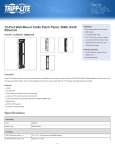
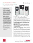
System Monitoring
and Troubleshooting
16
System Monitoring
and Troubleshooting
6–2
System Monitoring and Troubleshooting
Troubleshooting Suggestions
The Handheld is very useful in troubleshooting your machine. As with any problem,
you have to find it before you can fix it. There are several operations and features
that help you quickly find the exact cause of system problems.
S Monitor Discrete I/O Points — to examine I/O power flow for individual
I/O points.
S Force Discrete I/O Points — to examine machine sequences or
inconsistencies.
S Monitor Register Locations — to examine word locations to determine if
correct values are being used.
S Change Register Values — to force word locations with different values.
S Monitor Timer/Counter Values — to adjust machine timing elements.
S Understand Error Codes — to know where to look first.
6–3
System Monitoring and Troubleshooting
You can monitor up to 16 discrete points at one time. The points can be from the
following data types.
S Inputs
S Output
S Control relays
The status display area is also used to show the status for the points being
monitored. Here’s how the display is organized.
Indicates I/O
Status Display
16 LEDs Total
show on/off
status
Reference Number
n050
ADDRESS/DATA
ON/OFF
RUN BATT
PWR CPU
0
4
0
4
1
5
1
5
2
6
2
6
3
7
3
7
50–57
60–67
Use the following keystrokes to monitor discrete points. To select a different data
type, use the corresponding reference number instead of the one shown. The DL305
memory map is included in Appendix A. This will help you determine the appropriate
ranges for the various data types.
Select the reference number to monitor
SHF
5
0
MON
n050
ADDRESS/DATA
ON/OFF
RUN BATT
PWR CPU
0
4
0
4
1
5
1
5
2
6
2
6
3
7
3
7
Use PRV or NXT to scroll through the references (8 point increments)
PRV
n040
ADDRESS/DATA
ON/OFF
RUN BATT
PWR CPU
0
4
0
4
1
5
1
5
2
6
2
6
3
7
3
7
System Monitoring
and Troubleshooting
Monitoring Discrete Points
System Monitoring
and Troubleshooting
6–4
System Monitoring and Troubleshooting
Forcing Discrete Points
You can also force discrete points with the Handheld Programmer.
It is important to note that the DL305 CPUs only retain the forced value for one scan if
the output point is used in the logic program or if the input point used corresponds to
module that is installed in the base. The following example shows how the forcing
actually works.
Force 050 ON
Force I/O Points
000
002
005
001
003
010
Force 010 ON
007
050
004
051
END
On due to
010
forced ON
Next Scan
010 is off”
000
002
001
003
010
CPU reads the I/O status from
the modules. Sees that point 010
is off, overwrites force to turn off
010.
Read
Inputs
005
007
050
004
Force is overwritten
051
Logic is solved. Point 010,
even
though
previously
forced on, is turned off. Points
050 and 051 are turned off
since conditions are not met.
END
050 and 051
are off
Update
Outputs
CPU updates the output status
with the results obtained from the
logic execution. Y0 and Y1 were
turned off.
NOTE: If you use a CR as an input, you will not have the “one scan” problem.
6–5
System Monitoring and Troubleshooting
WARNING: Depending on your application, forcing I/O points may cause
unpredictable machine operation that can result in a risk of personal injury or
equipment damage.
To turn a point on
CLR
SET
SHF
Display returns to address display
5
0
0000
....
ADDRESS/DATA
ENT
ON/OFF
RUN BATT
PWR CPU
0
AND
1
OR
2
STR
3
NOT
4
OUT
5
TMR
6
CNT
7
SR
0
MCS
1
MCR
2
SET
3
RST
4
ADR
5
SHF
6
DATA
7
REG
0
4
0
4
1
5
1
5
2
6
2
6
3
7
3
7
Monitor the point to verify the force (optional)
CLR
SHF
5
0
MON
n050
ADDRESS/DATA
ON/OFF
RUN BATT
PWR CPU
To turn a point off
CLR
ENT
RST
SHF
Display returns to address display
5
0
0000
....
ADDRESS/DATA
ON/OFF
RUN BATT
PWR CPU
0
AND
1
OR
2
STR
3
NOT
4
OUT
5
TMR
6
CNT
7
SR
0
MCS
1
MCR
2
SET
3
RST
4
ADR
5
SHF
6
DATA
7
REG
System Monitoring
and Troubleshooting
The following example shows the keystrokes required to force an I/O point.
System Monitoring
and Troubleshooting
6–6
System Monitoring and Troubleshooting
Monitoring Register Locations
You can use the Handheld to monitor and change register locations. When a register
is monitored, the handheld programmer will display two register locations (eight bits
each) this means that 4 digits of data will be shown. Since data register locations are
8-bit locations, two consecutive data registers will be displayed. When changing
values in data register locations, you can also write two consecutive data register
locations.
Select the location to monitor
CLR
R
4
0
0
R401
R400
1453
ADDRESS/DATA
MON
ON/OFF
RUN BATT
PWR CPU
0
AND
1
OR
2
STR
3
NOT
4
OUT
5
TMR
6
CNT
7
SR
0
MCS
1
MCR
2
SET
3
RST
4
ADR
5
SHF
6
DATA
7
REG
0
AND
1
OR
2
STR
3
NOT
4
OUT
5
TMR
6
CNT
7
SR
0
MCS
1
MCR
2
SET
3
RST
4
ADR
5
SHF
6
DATA
7
REG
0
AND
1
OR
2
STR
3
NOT
4
OUT
5
TMR
6
CNT
7
SR
0
MCS
1
MCR
2
SET
3
RST
4
ADR
5
SHF
6
DATA
7
REG
Changing Register Values
Select the location to monitor
CLR
R
4
0
0
R401
R400
1453
ADDRESS/DATA
MON
ON/OFF
RUN BATT
PWR CPU
Enter the new value
SHF
ENT
1
3
R401
5
4
R400
1354
ADDRESS/DATA
ON/OFF
RUN BATT
PWR CPU
6–7
System Monitoring and Troubleshooting
You can also use the Handheld to monitor and/or change timer and counter current
values. There are two ways to do this. You can use the register monitoring procedure
discussed previously which will display the current value with the decimal point
implied for timers. The second method uses slightly different keystrokes and will
show timer current values with the decimal point. Using this method also uses the
instructions LEDs to indicate the last two digits of the timer/counter memory
reference.
Select the location to monitor
CLR
SHF
6
0
0
4569
.
ADDRESS/DATA
MON
Shows accumulated
time or count
ON/OFF
RUN BATT
PWR CPU
0
4
0
4
1
5
1
5
2
6
2
6
3
7
3
7
00–07
10–17
LEDs show last two digits of the
register reference number
Changing Timer/Counter Current Values
Select the timer location to monitor
CLR
SHF
6
0
0
4569
.
ADDRESS/DATA
MON
ON/OFF
RUN BATT
PWR CPU
0
4
0
4
1
5
1
5
2
6
2
6
3
7
3
7
0
4
0
4
1
5
1
5
2
6
2
6
3
7
3
7
Enter the new value
SHF
ENT
1
3
5
4
1354
.
ADDRESS/DATA
ON/OFF
RUN BATT
PWR CPU
System Monitoring
and Troubleshooting
Monitoring Timer/Counter Current Values
System Monitoring
and Troubleshooting
6–8
System Monitoring and Troubleshooting
Monitoring Program Stages
The RLL PLUS CPUs also have stages that can be monitored. This is especially useful
since it can quickly show you exactly which parts of the program are being executed.
The procedure is very similar to the one used for monitoring discrete I/O points.
Here’s how the display is organized.
Indicates
Stage Status
Display
16 LEDs Total
Show on/off
status
Stage Number
ADDRESS/DATA
ON/OFF
RUN BATT
PWR CPU
0
4
0
4
1
5
1
5
2
6
2
6
3
7
3
7
10–17
20–27
6–9
System Monitoring and Troubleshooting
Select the stage number to monitor
SG
SHF
1
0
MON
s010
ADDRESS/DATA
ON/OFF
RUN BATT
PWR CPU
0
4
0
4
1
5
1
5
2
6
2
6
3
7
3
7
Use PRV or NXT to scroll through the references (8 stage increments)
PRV
n020
ADDRESS/DATA
ON/OFF
RUN BATT
PWR CPU
0
4
0
4
1
5
1
5
2
6
2
6
3
7
3
7
System Monitoring
and Troubleshooting
Use the following keystrokes to monitor the stages.
System Monitoring
and Troubleshooting
6–10
System Monitoring and Troubleshooting
Forcing Program Stages
You can also force Program Stages with the Handheld Programmer. However, due
to the self-contained nature of this style of programming, you can really cause some
problems by forcing stages on and off.
It is important to note that the DL305 CPUs only retain the forced value for one scan if
the logic within the stage (or another stage) causes the status to be discarded. The
following example shows how the forcing actually works. Assume that the saw takes
approximately 10 seconds to reach the bottom limit. (Which is many, many, CPU
scans.)
Force a Stage ON
Stop
005
Stage
10
RST all stages
Jump to Stage 0
Stage 5 forced ON
Current Stage
ISG
0
Start
000
Stage
1
Pipe limit
001
Stage
2
Clamped
002
020
021
Converyor
SET
Clamp
Bottom
003
Stage
3
022
Stage
4
023
SET Saw
Saw Down
On
Top
004
Stage
5
024
022
021
Saw
Up
RST
Saw
Off
RST
Clamp
Next Scan
Stop
005
Stage
10
RST all stages
Clamp is reset,
which may cause a
saw jam.
Jump to Stage 0
ISG
0
Start
000
Stage
1
Pipe limit
001
Stage
2
Clamped
002
020
021
Converyor
SET
Clamp
Bottom
003
Stage
3
022
023
SET Saw
Saw Down
On
Stage
4
Top
004
Stage
5
024
022
021
Saw
Up
RST
Saw
Off
RST
Clamp
6–11
System Monitoring and Troubleshooting
WARNING: As shown in the example, forcing stages may cause unpredictable
machine operation that can result in a risk of personal injury or equipment
damage.
To turn a stage on
CLR
SET
SG
SHF
5
005
ADDRESS/DATA
ENT
ON/OFF
RUN BATT
PWR CPU
0
STR
1
AND
2
OR
3
NOT
4
ISG
5
JMP
6
SET
7
RST
0
SG
1
OUT
2
TMR
3
CNT
4
ADR
5
SHF
6
DATA
7
REG
0
4
0
4
1
5
1
5
2
6
2
6
3
7
3
7
0
STR
1
AND
2
OR
3
NOT
4
ISG
5
JMP
6
SET
7
RST
0
SG
1
OUT
2
TMR
3
CNT
4
ADR
5
SHF
6
DATA
7
REG
Monitor the stage to verify the force (optional)
CLR
SG
SHF
5
MON
s000
ADDRESS/DATA
ON/OFF
RUN BATT
PWR CPU
To turn a stage off
CLR
ENT
RST
SG
SHF
5
005
ADDRESS/DATA
ON/OFF
RUN BATT
PWR CPU
System Monitoring
and Troubleshooting
Obviously, there are times when it’s perfectly OK to force a program stage on or off.
The following example shows the keystrokes required to force an stage.
System Monitoring
and Troubleshooting
6–12
System Monitoring and Troubleshooting
Error Codes
The following table lists the error codes that may appear on the Handheld.
DL305 Error Code
Description
E01
Invalid Keystrokes
Invalid keystroke or series of keystrokes entered into the handheld
programmer. Refer to the DL305 Handheld Programmer manual for
assistance in the operation you are trying to perform.
E02
Input Point
Programmed as
Output
An I/O point dedicated to an input module has been used as an output in the
application program. Change the I/O reference number in the program which
is causing the error.
E03
Stack Overflow
The maximum number of instructions utilizing the internal stack has exceeded
eight. These instructions can be a combination of AND STRs, OR STRs and
MCS/MCR groups. Reduce the number of these instructions which are
pushed onto the stack at one time.
E05 (NON Stage)
Duplicate Coil
Reference
Two or more output coils have the same data type and number. Change the
duplicate coil to correct the error. Duplicate coil references are valid with the
SET instruction.
E05 (Stage)
Duplicate Stage
Reference
Two or more Stages have the same reference number. Change the duplicate
Stage number to correct the error.
E06
MCR/MCS Mismatch
The number of MCR instructions do not match the number of MCS
instructions. Each MCR must have an accompanying MCS.
E07
Missing CNT or SR
Contact
A required input contact is missing from a CNT (example, RESET input) or a
SR instruction. Refer to the DL305 User Manual for details on these
instructions.
E08
Invalid Data Values
The required data values for a TMR, CNT or SR are missing or incorrect.
Refer to the DL305 User Manual for details on these instructions.
E09
Incomplete Program
Rung
The rung does not terminate with an output as required. Program an output to
terminate the rung properly.
E11
Program Full
There is no available program addresses in memory. Reduce the size of the
program.
System Monitoring and Troubleshooting
6–13
Description
E21
Program Memory
Parity Error
A parity error has occurred in the program memory of the CPU. Clear the
memory and reload the program. If the error reoccurs replace the CPU.
Electrical noise will cause this problem.
E22
Password Error
The password stored in the CPU is invalid. Press the “CLR” key twice on the
handheld programmer and the password will be reset to 0000. Re-enter the
password if required.
E25
Tape/Program
Mismatch
A mismatch was found when a compare was performed on the program in
CPU memory and the program stored on tape.
E28
Volume Incorrect On
Tape Device.
The volume is incorrect on the tape player being used to load the program to
the CPU. Adjust the volume and retry the operation. Refer to the DL305
Handheld Programmer manual for details on tape operation.
E31
RAM Limit Exceeded
The application program required more RAM for execution than is available.
Reduce the length of the program.
E99
Instruction Not Found
A search was performed and the specified instruction was not found in the
application program.
System Monitoring
and Troubleshooting
DL305 Error Code