1
MOVIDYN®
Servo Controller
Manual
Single-Axis Positioning Control APA12 / API12
Edition 01/97
0922 8713 / 0197
16/042/95
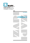
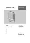
Illustration APA 12/API 12
Power supply
module
Axis module
APA12 / API12
single-axis
positioning
control
Plug
connector
CAN bus
Input
terminals
Output
terminals
Plug
connector
encoder
simulation
Slot for the option p.c.b.
Fig.1: View of the APA12/API12 option pcb installation
00004AEN
On compact servo controllers the slot for the option pcb is on the left-hand side, like on the axis module.
2
MOVIDYN ® APA 12/API 12
Important note
●
Please read this user manual carefully and thoroughly before installing and commissioning
the APA12/API 12 single-axis positioning control option of the MOVIDYN® Servo Controller.
It is assumed that engineers performing the work described in this user manual are familiar with
the MOVIDYN® Servo Controllers for DFY permanent-field synchronous motors (operating instructions) as well as the MD_SHELL user interface (user manual) and their operation.
●
Safety Notices
Strictly follow all warnings, precautions and safety notices contained in this manual.
Conventions used in this manual
Electrical hazard, e.g. when working on live equipment
Mechanical hazard, e.g. when working on hoists
Important note for safe and trouble-free operation of the driven machine/system,
e.g. presettings prior to commissioning. Failure to observe these notes may result
in serious risk of injury to yourself and others and damage to the equipment.
●
●
Cross-references are identified by a →
– (→ MD_SHELL) means
read up on this topic in the MD_SHELL manual or you will find more
detailed information there.
– (→ section x.x.) means
refer to section x.x. of this manual for additional information about
this topic.
Representation of menu items
Menu options etc of the MD_POS user interface which are referenced in the text are enclosed in
brackets [ ].
●
Each unit is manufactured and tested by SEW EURODRIVE in conformance with the applicable
technical documentation.
In the interest of technical progress, technical data and designs as well as the user interface
described herein are subject to change without notice.
Follow the instructions and notes contained in this manual to ensure trouble-free equipment
performance and best results.
Failure to observe this may result in a refusal of any subsequent warranty claim.
This manual also contains important service information. We therefore advise keeping it near the
unit.
MOVIDYN ® APA 12/API 12
3
Table of Contents
1
1.1
1.2
2
2.1
2.2
2.2.1
2.2.2
2.3
2.3.1
2.3.2
2.3.3
2.3.4
2.3.5
2.4
2.5
2.6
3
3.1
3.2
3.2.1
3.2.2
3.2.3
3.2.3.1
3.2.3.2
3.2.4
3.2.5
4
4.1
4.2
4.2.1
4.2.2
4.2.3
4.2.4
4.2.5
4.3
4.4
4.5
4.6
5
5.1
5.2
5.3
5.4
5.5
5.5.1
5.5.2
5.5.3
5.5.4
5.5.5
6
6.1
6.1.1
6.1.2
6.1.3
6.2
6.3
6.3.1
6.3.2
6.3.3
6.3.4
6.4
6.5
7
7.1
7.1.1
7.1.2
4
Installation . . . . . . . . . . . . . . . . . . . . . . . . . . . . . . . . . . .
Mechanical and electrical installation . . . . . . . . . . . . . . . . . .
Software installation . . . . . . . . . . . . . . . . . . . . . . . . . . .
Commissioning . . . . . . . . . . . . . . . . . . . . . . . . . . . . .
Safety notices . . . . . . . . . . . . . . . . . . . . . . . . . . . . . .
Activating the APA 12 / API 12 . . . . . . . . . . . . . . . . . . . . . . .
Preparatory work . . . . . . . . . . . . . . . . . . . . . . . . . . . . . . . . .
Connecting the APA 12 / API 12 . . . . . . . . . . . . . . . . . . . . . . . . .
Setting machine parameters . . . . . . . . . . . . . . . . . . . . . . .
Configuring terminals . . . . . . . . . . . . . . . . . . . . . . . . . . . . . .
Scaling travel parameters . . . . . . . . . . . . . . . . . . . . . . . . . . . .
Setting controller parameters . . . . . . . . . . . . . . . . . . . . . . . . . .
Programming reference travel . . . . . . . . . . . . . . . . . . . . . . . . . .
Saving machine parameters . . . . . . . . . . . . . . . . . . . . . . . . . . .
Setting encoder parameters . . . . . . . . . . . . . . . . . . . . . . .
Axis module (speed controller) . . . . . . . . . . . . . . . . . . . . . .
Performing a function test . . . . . . . . . . . . . . . . . . . . . . . .
Machine Parameters . . . . . . . . . . . . . . . . . . . . . . . . . . .
Overview/Value ranges . . . . . . . . . . . . . . . . . . . . . . . . . .
Parameter description . . . . . . . . . . . . . . . . . . . . . . . . . .
Input terminals . . . . . . . . . . . . . . . . . . . . . . . . . . . . . . . . . .
Output terminals . . . . . . . . . . . . . . . . . . . . . . . . . . . . . . . . .
Travel specific parameters . . . . . . . . . . . . . . . . . . . . . . . . . . . .
Determining the units for the travel specific parameters . . . . . . . . . . . . .
Determining travel specific parameters . . . . . . . . . . . . . . . . . . . . .
Reference travel parameters . . . . . . . . . . . . . . . . . . . . . . . . . . .
Control specific parameters of the position controller . . . . . . . . . . . . . .
Working with the APA 12 / API 12 . . . . . . . . . . . . . . . . . . . . . . . .
Switching on the APA 12 / API 12 positioning control . . . . . . . . . . .
Operating modes of the APA 12 / API 12 positioning control . . . . . . . .
Overview of operating modes . . . . . . . . . . . . . . . . . . . . . . . . . .
Performing a reference travel . . . . . . . . . . . . . . . . . . . . . . . . . .
Jogging mode . . . . . . . . . . . . . . . . . . . . . . . . . . . . . . . . . .
Set-up/Remote mode (manual mode) . . . . . . . . . . . . . . . . . . . . . .
Automatic mode . . . . . . . . . . . . . . . . . . . . . . . . . . . . . . . . .
Editing machine parameters . . . . . . . . . . . . . . . . . . . . . . .
Entering programs . . . . . . . . . . . . . . . . . . . . . . . . . . . .
Saving data . . . . . . . . . . . . . . . . . . . . . . . . . . . . . . .
Exiting MD_POS . . . . . . . . . . . . . . . . . . . . . . . . . . . . .
Service Information . . . . . . . . . . . . . . . . . . . . . . . . . . .
Diagnosis menu . . . . . . . . . . . . . . . . . . . . . . . . . . . . .
Status display . . . . . . . . . . . . . . . . . . . . . . . . . . . . . .
Fault report . . . . . . . . . . . . . . . . . . . . . . . . . . . . . . .
Status report . . . . . . . . . . . . . . . . . . . . . . . . . . . . . . .
Fault messages/Fault elimination . . . . . . . . . . . . . . . . . . . . .
Fault messages . . . . . . . . . . . . . . . . . . . . . . . . . . . . . . . . . .
List of fault messages . . . . . . . . . . . . . . . . . . . . . . . . . . . . . .
Resetting a fault . . . . . . . . . . . . . . . . . . . . . . . . . . . . . . . . .
Responding to an EMERGENCY STOP . . . . . . . . . . . . . . . . . . . . . .
Emergency stop with continuation of program at stopped program line . . . .
MD_POS User Interface . . . . . . . . . . . . . . . . . . . . . . . . .
General notes on how to operate MD_POS . . . . . . . . . . . . . . . .
Operating the user interface . . . . . . . . . . . . . . . . . . . . . . . . . . .
Explaining the selection fields in the menus . . . . . . . . . . . . . . . . . . .
Selection windows . . . . . . . . . . . . . . . . . . . . . . . . . . . . . . . .
Main menu . . . . . . . . . . . . . . . . . . . . . . . . . . . . . . . .
MD_POS menu structure . . . . . . . . . . . . . . . . . . . . . . . . .
Programming menu . . . . . . . . . . . . . . . . . . . . . . . . . . . . . . .
Set-up menu . . . . . . . . . . . . . . . . . . . . . . . . . . . . . . . . . . .
Diagnosis . . . . . . . . . . . . . . . . . . . . . . . . . . . . . . . . . . . .
Configuration . . . . . . . . . . . . . . . . . . . . . . . . . . . . . . . . . . .
Exiting the program . . . . . . . . . . . . . . . . . . . . . . . . . . .
Help feature . . . . . . . . . . . . . . . . . . . . . . . . . . . . . . .
Travel Programs . . . . . . . . . . . . . . . . . . . . . . . . . . . . . . . .
Programming travel programs . . . . . . . . . . . . . . . . . . . . . . . . . .
Program editor . . . . . . . . . . . . . . . . . . . . . . . . . . . . . . . . . .
Program structure . . . . . . . . . . . . . . . . . . . . . . . . . . . . . . . .
.
.
.
.
.
.
.
.
.
.
.
.
.
.
.
.
.
.
.
.
.
.
.
.
.
.
.
.
.
.
.
.
.
.
.
.
.
.
.
.
.
.
.
.
.
.
.
.
.
.
.
.
.
.
.
.
.
.
.
.
.
.
.
.
.
.
.
.
.
.
.
.
.
.
.
.
.
.
.
.
.
.
.
.
.
.
.
.
.
.
.
.
.
.
.
.
.
.
.
.
.
.
.
.
.
.
.
.
.
.
.
.
.
.
.
.
.
.
.
.
.
.
.
.
.
.
.
.
.
.
.
.
.
.
.
.
.
.
.
.
.
.
.
.
.
.
.
.
.
.
.
.
.
.
.
.
.
.
.
.
.
.
.
.
.
.
.
.
.
.
.
.
.
.
.
.
.
.
.
.
.
.
.
.
.
.
.
.
.
.
.
.
.
.
.
.
.
.
.
.
.
. . . . . . .
. . . . . .
. . . . . .
. . . . . .
. . . . . .
. . . . . .
. . . . . . .
. . . . . . .
. . . . . .
. . . . . . .
. . . . . . .
. . . . . . .
. . . . . . .
. . . . . . .
. . . . . .
. . . . . .
. . . . . .
. . . . . .
. . . . . .
. . . . . .
. . . . . . .
. . . . . . .
. . . . . . .
. . . . . . .
. . . . . . .
. . . . . . .
. . . . . . .
. . . . . . .
. . . . . .
. . . . . .
. . . . . . .
. . . . . . .
. . . . . . .
. . . . . . .
. . . . . . .
. . . . . .
. . . . . .
. . . . . .
. . . . . .
. . . . . .
. . . . . .
. . . . . .
. . . . . .
. . . . . .
. . . . . .
. . . . . . .
. . . . . . .
. . . . . . .
. . . . . . .
. . . . . . .
. . . . . .
. . . . . .
. . . . . . .
. . . . . . .
. . . . . . .
. . . . . .
. . . . . .
. . . . . . .
. . . . . . .
. . . . . . .
. . . . . . .
. . . . . .
. . . . . .
. . . . . . .
. . . . . . .
. . . . . . .
. . . . . . .
.
.
.
.
.
.
.
.
.
.
.
.
.
.
.
.
.
.
.
.
.
.
.
.
.
.
.
.
.
.
.
.
.
.
.
.
.
.
.
.
.
.
.
.
.
.
.
.
.
.
.
.
.
.
.
.
.
.
.
.
.
.
.
.
.
.
.
.
.
.
.
.
.
.
.
.
.
.
.
.
.
.
.
.
.
.
.
.
.
.
.
.
.
.
.
.
.
.
.
.
.
.
.
.
.
.
.
.
.
.
.
.
.
.
.
.
.
.
.
.
.
.
.
.
.
.
.
.
.
.
.
.
.
.
.
.
.
.
.
.
.
.
.
.
.
.
.
.
.
.
.
.
.
.
.
.
.
.
.
.
.
.
.
.
.
.
.
.
.
.
.
.
.
.
.
.
.
.
.
.
.
.
.
.
.
.
.
.
.
.
.
.
.
.
.
.
.
.
.
.
.
. .6
. 6
. 13
. 15
. 15
. 15
. 15
. 16
. 16
. 17
. 18
. 20
. 20
. 21
. 22
. 23
. 24
. 26
. 26
. 28
. 28
. 33
. 36
. 36
. 41
. 47
. 51
. 52
. 52
. 52
. 52
. 52
. 54
. 55
. 58
. 58
. 59
. 60
. 61
. 62
. 62
. 62
. 65
. 65
. 66
. 66
. 66
. 69
. 69
. 72
. 73
. 73
. 73
. 73
. 75
. 78
. 79
. 80
. 81
. 82
. 82
. 83
. 83
. 85
. 85
. 85
. 87
MOVIDYN ® APA 12/API 12
Table of Contents
7.1.3
7.2
7.2.1
7.2.2
7.2.2.1
7.2.2.2
7.2.2.3
7.2.2.4
7.2.2.5
7.2.2.6
7.2.2.7
7.2.2.8
7.2.2.9
7.2.2.10
7.2.2.11
7.2.2.12
7.2.3
7.3
7.3.1
7.3.2
7.3.2.1
7.3.2.2
7.3.2.3
7.3.2.4
7.3.2.5
7.4
7.5
7.6
7.7
7.8
7.9
8
8.1
8.1.1
8.1.2
8.2
8.2.1
8.2.2
8.2.3
8.2.4
8.2.5
8.2.6
8.2.7
8.2.8
8.3
8.3.1
8.3.2
8.3.3
8.4
8.4.1
8.4.2
9
9.1
9.1.1
9.1.2
9.2
9.2.1
9.2.2
9.3
9.3.1
9.3.2
9.4
9.4.1
9.4.2
10
Commands in travel programs . . . . . . . . . . . . . . . . . . . . . . . . . .
Commands for manual mode . . . . . . . . . . . . . . . . . . . . . . . .
Entering commands . . . . . . . . . . . . . . . . . . . . . . . . . . . . . . . .
Data management . . . . . . . . . . . . . . . . . . . . . . . . . . . . . . . . .
Overview of data management commands . . . . . . . . . . . . . . . . . . . .
Transferring/Requesting programs . . . . . . . . . . . . . . . . . . . . . . . .
Deleting a program line . . . . . . . . . . . . . . . . . . . . . . . . . . . . . .
Requesting directory . . . . . . . . . . . . . . . . . . . . . . . . . . . . . . .
Storing data in the flash EPROM . . . . . . . . . . . . . . . . . . . . . . . . .
Transferring and requesting machine parameters . . . . . . . . . . . . . . . . .
Transferring and requesting variables (H00 ... H99) . . . . . . . . . . . . . . .
Transferring and requesting counters (C00 ... C99) . . . . . . . . . . . . . . . .
Transferring and requesting table positions (T00 ... T15) . . . . . . . . . . . . .
Requesting flags (M00 ... M99) . . . . . . . . . . . . . . . . . . . . . . . . . .
Requesting encoder position (only with SSI module) . . . . . . . . . . . . . . .
Switching manual mode on and off . . . . . . . . . . . . . . . . . . . . . . . .
Commands in manual mode . . . . . . . . . . . . . . . . . . . . . . . . . . .
Commands . . . . . . . . . . . . . . . . . . . . . . . . . . . . . . . .
Overview . . . . . . . . . . . . . . . . . . . . . . . . . . . . . . . . . . . . .
Detailed discussion of the commands . . . . . . . . . . . . . . . . . . . . . .
Jump instructions / Program calls . . . . . . . . . . . . . . . . . . . . . . . .
Set commands . . . . . . . . . . . . . . . . . . . . . . . . . . . . . . . . . .
Position and travel commands . . . . . . . . . . . . . . . . . . . . . . . . . .
Wait commands . . . . . . . . . . . . . . . . . . . . . . . . . . . . . . . . . .
Status commands . . . . . . . . . . . . . . . . . . . . . . . . . . . . . . . . .
Variables . . . . . . . . . . . . . . . . . . . . . . . . . . . . . . . . .
Table positions . . . . . . . . . . . . . . . . . . . . . . . . . . . . . .
Flags . . . . . . . . . . . . . . . . . . . . . . . . . . . . . . . . . . .
Counters . . . . . . . . . . . . . . . . . . . . . . . . . . . . . . . . .
Timers . . . . . . . . . . . . . . . . . . . . . . . . . . . . . . . . . .
Program examples . . . . . . . . . . . . . . . . . . . . . . . . . . . .
Application Notes . . . . . . . . . . . . . . . . . . . . . . . . . . . . .
Wiring diagrams . . . . . . . . . . . . . . . . . . . . . . . . . . . . . .
Connection of the APA 12 / API 12 with internal 24V power supply . . . . . . .
Connection of the APA 12 / API 12 with internal and external 24V power supply
Example for setting and calculating the machine parameters . . . . . . . .
General . . . . . . . . . . . . . . . . . . . . . . . . . . . . . . . . . . . . . .
Description of the positioning task . . . . . . . . . . . . . . . . . . . . . . . .
Setting the machine parameters for the sample application . . . . . . . . . . .
Calculating machine parameters K10-K13 . . . . . . . . . . . . . . . . . . . .
Resolution of distance travelled (K10/K11) . . . . . . . . . . . . . . . . . . . .
Speed resolution (K12) . . . . . . . . . . . . . . . . . . . . . . . . . . . . . .
Resolution acceleration/deceleration (K13) . . . . . . . . . . . . . . . . . . . .
Acceleration/deceleration K16/K17 . . . . . . . . . . . . . . . . . . . . . . . .
Example: hoist . . . . . . . . . . . . . . . . . . . . . . . . . . . . . .
General notes . . . . . . . . . . . . . . . . . . . . . . . . . . . . . . . . . . .
Example 1: Encoder zero point outside of the working range . . . . . . . . . . .
Example 2: Encoder zero point inside of the working range . . . . . . . . . . .
Positioning with the touch probe . . . . . . . . . . . . . . . . . . . . . .
Description of the touch probe . . . . . . . . . . . . . . . . . . . . . . . . . .
Touch probe application examples . . . . . . . . . . . . . . . . . . . . . . . .
Technical Data . . . . . . . . . . . . . . . . . . . . . . . . . . . . . .
Input terminals . . . . . . . . . . . . . . . . . . . . . . . . . . . . . .
Mechanical design . . . . . . . . . . . . . . . . . . . . . . . . . . . . . . . .
Electrical specifications . . . . . . . . . . . . . . . . . . . . . . . . . . . . . .
Output terminals . . . . . . . . . . . . . . . . . . . . . . . . . . . . . .
Mechanical design . . . . . . . . . . . . . . . . . . . . . . . . . . . . . . . .
Electrical specifications . . . . . . . . . . . . . . . . . . . . . . . . . . . . . .
Encoder connection . . . . . . . . . . . . . . . . . . . . . . . . . . . .
Mechanical design . . . . . . . . . . . . . . . . . . . . . . . . . . . . . . . .
Electrical specifications . . . . . . . . . . . . . . . . . . . . . . . . . . . . . .
CAN connection . . . . . . . . . . . . . . . . . . . . . . . . . . . . . .
Mechanical design . . . . . . . . . . . . . . . . . . . . . . . . . . . . . . . .
Electrical specifications . . . . . . . . . . . . . . . . . . . . . . . . . . . . . .
Index . . . . . . . . . . . . . . . . . . . . . . . . . . . . . . . . . . .
MOVIDYN ® APA 12/API 12
.
.
.
.
.
.
.
.
.
.
.
.
.
.
.
.
.
.
.
.
.
.
.
.
.
.
.
.
.
.
.
.
.
.
.
.
.
.
.
.
.
.
.
.
.
.
.
.
.
.
.
.
.
.
.
.
.
.
.
.
.
.
.
.
.
.
.
.
.
.
.
.
.
.
.
.
.
.
.
.
.
.
.
.
.
.
.
.
.
.
.
.
.
.
.
.
.
.
.
.
.
.
.
.
.
.
.
.
.
.
.
.
.
.
.
.
.
.
.
.
.
.
.
.
.
.
.
.
.
.
. . . . . .
. . . . .
. . . . . .
. . . . . .
. . . . . .
. . . . . .
. . . . . .
. . . . . .
. . . . . .
. . . . . .
. . . . . .
. . . . . .
. . . . . .
. . . . . .
. . . . . .
. . . . . .
. . . . . .
. . . . .
. . . . . .
. . . . . .
. . . . . .
. . . . . .
. . . . . .
. . . . . .
. . . . . .
. . . . .
. . . . .
. . . . .
. . . . .
. . . . .
. . . . .
. . . . .
. . . . .
. . . . . .
. . . . . .
. . . . .
. . . . . .
. . . . . .
. . . . . .
. . . . . .
. . . . . .
. . . . . .
. . . . . .
. . . . . .
. . . . .
. . . . . .
. . . . . .
. . . . . .
. . . . .
. . . . . .
. . . . . .
. . . . .
. . . . .
. . . . . .
. . . . . .
. . . . .
. . . . . .
. . . . . .
. . . . .
. . . . . .
. . . . . .
. . . . .
. . . . . .
. . . . . .
. . . . .
.
.
.
.
.
.
.
.
.
.
.
.
.
.
.
.
.
.
.
.
.
.
.
.
.
.
.
.
.
.
.
.
.
.
.
.
.
.
.
.
.
.
.
.
.
.
.
.
.
.
.
.
.
.
.
.
.
.
.
.
.
.
.
.
.
.
.
.
.
.
.
.
.
.
.
.
.
.
.
.
.
.
.
.
.
.
.
.
.
.
.
.
.
.
.
.
.
.
.
.
.
.
.
.
.
.
.
.
.
.
.
.
.
.
.
.
.
.
.
.
.
.
.
.
.
.
.
.
.
.
.
.
.
.
.
.
.
.
.
.
.
.
.
.
.
.
.
.
.
.
.
.
.
.
.
.
.
.
.
.
.
.
.
.
.
.
.
.
.
.
.
.
.
.
.
.
.
.
.
.
.
.
.
.
.
.
.
.
.
.
.
.
.
.
.
. . . 88
. . 88
. . . 88
. . . 88
. . . 89
. . . 89
. . . 90
. . . 90
. . . 90
. . . 90
. . . 91
. . . 91
. . . 92
. . . 92
. . . 93
. . . 93
. . . 93
. . 94
. . . 94
. . . 97
. . . 97
. . 101
. . 106
. . 109
. . 110
. 111
. 113
. 115
. 115
. 115
. 116
. 120
. 120
. . 120
. . 121
. 122
. . 122
. . 122
. . 124
. . 125
. . 125
. . 125
. . 125
. . 126
. 126
. . 126
. . 127
. . 128
. 129
. . 129
. . 130
. 132
. 132
. . 132
. . 132
. 132
. . 132
. . 132
. 133
. . 133
. . 133
. 134
. . 134
. . 134
. 135
5
1
Installation
●
The positioning module may only be installed by qualified and trained electrical personnel in
conformance with the applicable accident prevention regulations and installation instructions (e.g.
EN 60204) and as shown in the connection diagram.
●
With their cover removed the units have enclosure type IP 00 with dangerous voltages present at
some places. After commissioning, i.e. when in operation, the cover must be replaced to provide
protection.
●
Protective measures and equipment must be chosen according to the applicable standards
(e.g. EN 60 204).
●
When installing and commissioning the unit, strictly observe the applicable instructions.
1
Installation
1.1
Mechanical and electrical installation
Installing the option p.c.b.
The APA12/API 12 single-axis positioning module is plugged into the option p.c.b. slot of the MOVIDYN®
axis module (see Fig. 2).
Before starting
●
Make sure that the power supply and axis module(s) of the MOVIDYN® Servo Controller have
been properly installed and commissioned (see the MOVIDYN® Servo Controller Operating
Instructions, sections 1 and 2).
Plugging in the APA12/API12 positioning module
●
Disconnect the MOVIDYN® Servo Controller from the supply (de-energize). Also disconnect any
separate-source voltages that may be applied (like an external 24 VDC supply).
●
Remove the cover from the option p.c.b. slot (2 screws for type MAS...).
Care must be taken to prevent any damage to the p.c.b. as a result of electrostatic discharge (e.g.
improper handling by commissioning personnel).
6
●
Before touching the p.c.b. make sure you have taken appropriate e.s.d. measures (wrist strap,
conductive shoes, etc.).
●
Position the p.c.b in the guide rails of the option slot with the backplane connector to the rear.
Make sure the p.c.b. sits properly in the rear guide rails.
●
Press the backplane connector of the p.c.b. into the socket in the axis module housing. The p.c.b.
sockets must be flush with the axis module cover.
●
Cover the p.c.b. slot with the cover supplied with the p.c.b. and screw tight (MAS... only).
MOVIDYN ® APA 12/API 12
Installation
APA12 / API12
Cover plate
Guide rails
Backplane connector
Fig.2: Installation of the APA 12 / API 12 single-axis positioning control option
00005AEN
Connecting the leads
The single-axis positioning p.c.b. has pluggable terminals. The plugs are supplied with the p.c.b. and
come plugged into the sockets.
MOVIDYN ® APA 12/API 12
7
1
Installation
●
Encoder connection
The API 12 can be operated with the encoder simulation provided by the axis module or with an external
encoder for sensing the actual position, whereas the APA 12 may only be operated together with an
external encoder.
The encoder simulation provides track signals A, A, B, B and the zero pulse C, C. The signals are output
in conformance with the RS-422 standard. They are generated from the resolver signals of the motor
connected at the axis module. A resolution of 1024 pulses/revolution of the motor is provided. This
resolution cannot be changed.
If an external encoder is used, the encoder must have its own voltage supply for the encoder electronics.
The voltage source of the API 12 is +15V (-0.5/+2V) with a maximum ampacity of 240 mA.
An external encoder for the API 12 should have the complementary signals A, A, B, B and the zero pulse
output C, C pursuant to RS-422 specification. However, it is also possible to connect unipolar encoders
with signals A, B, C. The zero pulse of the encoder is crucial for determining the home position when a
reference travel is performed.
The external encoder for the APA 12 must supply the data + and data - signals. From the APA 12 the
external encoder receives the pulse + and pulse - signals.
The encoder simulation of the axis module is factory-connected to the positioning if the API 12 is supplied
with the axis module. If the API 12 is ordered and supplied separately, the necessary connections are
enclosed in the package.
m
s
c
Channel
Channel
Channel
Figure 3: Connection of the encoder simulation for the API 12
0006AEN
Caution
If the encoder simulation/the encoder and the APA 12/API 12 are not connected correctly, the axis may
start moving during commissioning without any form of control!
●
Establish all electrical connections as shown in the wiring diagrams. Also see the notes below,
the illustration “Terminal assignment” and the table “Terminal functions”.
– Connect all conductors to the respective terminals of the plug. Make sure that all terminals are
screwed tight.
– Plug all plugs into the correct sockets.
– Run signal leads separate from power leads.
Wiring examples: see section 8.1
8
MOVIDYN ® APA 12/API 12
Installation
1
Installing the encoder
The absolute encoder is connected to terminals X11/32-33 (pulses), X11/34-35 (data) and X11/38-39
(power supply).
Recommended cable:
6 x 0.25 mm2 twisted pair, shielded
39 Ω / km line resistance
120 Ω surge resistance
Internal Encoder Supply
External Encoder Supply
X11
X11
1
2
3
4
1
2
3
4
CAN+
CANGND
CAN+
CANGND
twisted pair, shielded
twisted pair, shielded
31
32
33
34
35
36
37
38
39
31
32
33
34
35
36
37
38
39
+24V Input
Pulse +
Pulse Data +
Data not assigned
not assigned
GND
+15V
+24V Input
Pulse +
Pulse Data +
Data not assigned
not assigned
GND
+15V
1.)
1.)
2.)
2.)
Encoder
Encoder
+ VDC
-
GND
GND
PE
2.)
3.)
VAC
Fig. 4: Connection with internal and external encoder supply
00169AEN
1.)
Earthing is to be provided once on the MOVIDYN® ; maximum lead length between encoder and MOVIDYN®: 100m
2.)
Earthing as recommended by the manufacturer (recommended: capacitance earth, C = 22nF)
3.)
Power supply (electrically isolated)
Notes on connecting the module (refer to Fig. 5)
●
Please observe the notes and recommendations in the MOVIDYN® Servo Controller Operating
Instructions , section 2.8.
●
The input and output terminal connections shown in the terminal assignment diagram depict a
standard implementation. All freely programmable terminals must be connected in accordance
with your wiring diagrams.
●
Max. lead cross section: 0.75 mm2
●
Voltage output 24 V (terminals X11/13, X11/14):
Voltage input 24 V to supply the binary outputs (terminals 30, 31):
MOVIDYN ® APA 12/API 12
9
1
Installation
If the load at terminals X11/13 and X11/14 from all activated binary inputs and binary outputs is
< 180 mA, this voltage supply can be used to activate the respective inputs and outputs. In this
case a jumper is placed between terminals 30 and 13 and between terminals 31 and 14 (wiring
example see section 8.1).
For output currents > 180 mA an external voltage supply is required. In this case terminals 13 and
14 are not needed in order to supply the output terminals (see section 8.1).
●
Limit switch connection:
Limit switches to limit the travel are connected to input terminals X21/7 and X21/8 of the axis
module. These terminals must then be programmed to the functions “limit switch ccw” and “limit
switch cw” respectively (see MD_SHELL). The limit switches must be zero-active (normally
closed).
●
Override connection:
To execute a sequence programmed in a travel program with a speed greater or less than the one
programmed, an analog setpoint can be applied to input terminals X21/2 and X21/3. This allows
you to operate with a travelling speed between 0 and 150% (0V to 10V) of the programmed speed
(e.g. for set-up purposes).
Note
Output X21/1 may be used as a voltage supply for an externally connected potentiometer used to operate
the override.
●
Intalling the Can bus
3)
2)
R = 120 Ω
CAN+
CANGND
GND
+ 15 V
1)
2)
3)
X11
X11
X11
X11
1
2
3
4
5
6
7
8
1
2
3
4
5
6
7
8
1
2
3
4
5
6
7
8
1
2
3
4
5
6
7
8
35
36
37
38
39
35
36
37
38
39
35
36
37
38
39
35
36
37
38
39
1)
1)
1)
The jumber shown under 1) is only necessary if multiple independently powered axes (e.g. compact axes) are
connected (maximum length 2 m). It is not necessary if axis modules are interconnected and supplied from a single
power source.
The shield of the CAN cable may only be earthed directly once.
If further earthing measures are required, these must be implemented by means of a capacitor (C = 2 nF, RF earth)
Fig. 5: Installing the CAN bus
10
R = 120 Ω
00007AEN
MOVIDYN ® APA 12/API 12
Installation
1
The CAN bus is connected to terminals X11/1 (CAN+), X11/2 (CAN-), and X11/3 (GND), directly from axis
to axis (see Figure 5). The first and last station on the bus must be terminated with a 120 Ω resistor.
Recommended cable
– 4 x 0.5 mm2 twisted pair, shielded
– 39 Ω / km line resistance
– 120 Ω surge resistance
Terminal assignment
APA12
API12
X11
CAN +
CAN GND
1
2
3
Automatic/Manual
Start program or reference travel
Feed enable
Read-in enable
Reference cam
Jog +
Jog Touch Probe
Programmable
0V24
24V supply for
ext. components
+ 24V
4
5
6
7
8
9
10
11
12
13
14
15
16
17
18
19
20
21
Programmable
Program end
Axis in position
Reference travel defined
Programmable
Touch Probe active
Breakpoint logic active
Fault signal
Programmable
External
24V supply
Absolute
value encoder
with SSI
Encoder
supply
Fig.6:
0V24
+24 V
Cycle +
Cycle Data +
Data not used
not used
0V15
+ 15V
22
23
24
25
26
27
28
29
30
31
32
33
34
35
36
37
38
39
X11
CAN +
CAN GND
CAN-Bus
Automatic/Manual
Start Program or reference travel
Feed enable
Read-in enable
Reference cam
Jog +
Jog Touch Probe
Input
terminals
24V supply for
ext. components
Programmable
0V24
+ 24V
Programmable
Programmable
Output
terminals
Program end
Axis in position
Reference travel defined
Touch Probe active
Breakpoint logic active
Fault signal
Programmable
24V
Supply
Encoder
connection
External
24V supply
A
A
Incremental encoder
B
or
B
encoder simulation
from servo controller C
C
Optional encoder 0V15
supply
+ 15V
Terminal assignment of the APA 12 / API 12 single-axis positioning control option
MOVIDYN ® APA 12/API 12
0V24
+24 V
1
2
3
CAN Bus
4
5
6
7
8
9
10
11
12
13
14
15
16
17
18
19
20
21
Input
terminals
22
23
24
25
26
27
28
29
30
31
32
33
34
35
36
37
38
39
Output
terminals
24V
Supply
Encoder
connection
MD0029GB
11
1
Installation
Function
CAN bus
Binary inputs
fixed
fixed
fixed
fixed
fixed
fixed
fixed
fixed
fixed
Plug
X11
Term.
1, 2, 3
4
5
6
7
8
9
10
11
12
15 ... 21
Voltage output 24 V
for supply of binary inputs and outputs
13
14
Binary outputs
freely programmable
freely programmable
freely programmable
freely programmable
freely programmable
freely programmable
freely programmable
freely programmable
Voltage input 24V1)
for supply of binary outputs
Input encoder
22
23
24
25
26
27
28
29
30
31
32, 33
34, 35
36, 37
38
Output voltage supply for ext. encoder
39
Characteristics
Baud rate 500 KBit/s
as per DIN 19240
Automatic/Manual
Progr./Ref. travel start
"1": +13V to
Feed enable
+30.2V
Read-in enable
Reference cam
typical: 24V (6mA)
Jogging +
Jogging "0": -3V to
Touch probe
+5V
0V24 = Reference potential 24 V Ampacity:
+24V ± 1V
max. 180mA
as per DIN 19240
Program end
Axis in position
"1": + 2 4V
Reference position defined
max. 500 mA
Touch probe zero point logic active per output
Breakpoint active
(ohmic load)
Fault signal
0V24 (A) = reference potential 24 V
+ 24 V (A)
APA 12: pulse+, pulseRS-422 level
API 12: A, A
APA 12: data+, dataAPI 12:B, B
APA 12: not assigned;
API 12: C, C
0V15 = Reference potential
(Encoder simulation or external Current rating:
encoder)
max. 240 mA
+ 15V - 0.5/+2V
Table: APA 12/API 12 terminal functions
1)
Please read the notes on connecting the module in this section
Function
Voltage output 10 V for override
Analog inputs
Binary inputs
Plug
X21
Term.
1
2
3
5
6
7
8
Characteristics
+10V (max. 3mA)
Voltage input override 0 ... 10 V
Reference potential override
Control inhibit
Freely programmable
Limit switch CW
Limit switch CCW
as per DIN 19240
"1": +13V to
+ 30.2V
typical: 24V (6mA)
"0": - 3V to
+ 5V
Table: Terminal functions on the axis module
12
MOVIDYN ® APA 12/API 12
Installation
1.2
1
Software installation
The engineer commissioning the APA 12/API 12 single-axis positioning control must be familiar with
– the MOVIDYN® Servo Controller (mains and axis module),
– the operation of an MS-DOS PC and
– the MD_SHELL user interface used for configuring the positioning control.
Therefore basic operating steps are not discussed in the following instructions.
Connecting the PC
●
Connect a PC, which meets the necessary hardware requirements, to the serial interface of the
power supply module (see MD_SHELL, section 2.1).
Installing the software
●
Insert the program diskette with the MD_POS program into the disk drive.
●
Change to the drive where you have placed the installation diskette.
●
Where MD_POS will be installed depends on where MD_SHELL is installed or will be installed.
After the installation of MD_POS is complete, the MD_POS and MD_SHELL directories must be
on the same hierarchical level. Below are two installation examples.
Example a)
MD_SHELL is located in the MD_SHELL directory on the C drive (hard disk)
Enter the following command:
INSTALL C:\MD_POS
After copying is complete you will find the following structure:
Generally, three languages are available: German, English and French.
C:\
MD_SHELL\
MD_POS\
DEUTSCH\
ENGLISH\
FRANZ\
DATEN\
MD_POS .EXE
MD_POSA.EXE
POS_INFO.CFG
INSTALL.BAT
ACHSPRG.WRK
GEBERTYP.DAT
KONFIG.DAT
MOVIDYN ® APA 12/API 12
13
1
Installation
Example b)
MD_SHELL is located in a subdirectory on the C drive (hard disk), e.g. C:\SEW\MD_SHELL
Enter the following DOS command:
INSTALL C:\SEW\MD_POS
After copying is completed you will find the following structure:
Generally, three languages are available: German, English and French
C:\
SEW\
MD_SHELL\
MD_POS\
DEUTSCH\
ENGLISCH\
FRANZ\
DATEN\
MD_POS .EXE
MD_POSA.EXE
POS_INFO.CFG
INSTALL.BAT
ACHSPRG.WRK
GEBERTYP.DAT
KONFIG.DAT
●
Check the subdirectory structure by entering:
C:\MD_POS dir or C:\SEW\MD_POS dir
If you have installed the files as shown in example b) you will have to enter the following changes:
●
Edit the following files:
a) POS_INFO.CFG
is located in the MD_POS directory
Change to the MD_POS directory
EDIT POS_INFO.CFG
(calls the editor)
Add the path name from where MD_SHELL is called (2nd line).
In the above example: C:\SEW\MD_SHELL
b) MD_SHELL
is located in the MD_SHELL directory
Change to the MD_SHELL directory
EDIT MD_SHELL.INI
(calls the editor)
Add the path name from where MD_SCOPE is to be called (8th line).
In the above example: C:\SEW\MD_SCOPE
Add the path name from where MD_POS is to be called (9th line).
In the above example: C:\SEW\MD_POS
If the installation was carried out as shown in example a) no further modifications are needed.
The necessary software to operate the APA 12/API 12 single-axis positioning control is now installed on
your PC.
You may start commissioning the APA 12/API 12 single axis positioning control (see section 2).
14
MOVIDYN ® APA 12/API 12
Commissioning
2
Commissioning
2.1
Safety Notices
●
Commissioning and service work on the unit may only be carried out by qualified and trained
electrical personnel in conformance with the applicable accident prevention regulations and in
strict compliance with all other applicable regulations and standards (e.g. EN 60204).
●
Before removing the protective cover disconnect the unit from the mains. Dangerous voltages may
prevail up to 10 minutes after power-down.
●
With the protective cover, removed the unit has enclosure type IP 00.
Only the electronic terminals carry low voltages.
The upper components of the unit carry dangerous voltages!
●
When the unit is energized, dangerous voltages are present at the output terminals, cables and
motor terminals connected to them. This is also the case if the unit is disabled and the motor is
at rest.
●
Unlighted operating LEDs or other display elements are no indication that the unit is disconnected
from the mains and de-energized.
●
Internal safety features or mechanical blocking of the unit may cause the motor to stop. Eliminating
the cause of the fault may cause the drive to restart automatically.
If automatic restart is not acceptable for the given application on the grounds of safety reasons,
the unit must be disconnected from the mains prior to eliminating the fault. In this case activation
of the “Auto reset” feature (P630) is strictly prohibited!
●
If there is no encoder connected to the actual value inputs of the APA 12/API 12, there is the danger
that the axis will start up uncontrolled during commissioning, as the position controller does not
receive an actual value signal!
2.2
2
Activating the APA 12/API 12
2.2.1 Preparatory work
The MOVIDYN® Servo Controller and the APA 12/API 12 single-axis positioning control are programmed
solely via a PC with the supplied MD_SHELL user interface and the MD_POS interface for the positioning
control option respectively. Operation of the MD_SHELL interface is explained in the MD_SHELL manual
(see MD_SHELL).
●
Connect the switched-off power supply module to the PC with the interface cable if not already
connected.
●
Power up the MOVIDYN® Servo Controller.
●
Start MD_SHELL.
●
Select the PC serial interface to which the power supply module is connected.
MOVIDYN ® APA 12/API 12
15
2
Commissioning
●
Start up the MOVIDYN® Servo Controller (see the MOVIDYN® Servo Controller Installation and
Operating Instructions):
– Set axes addresses.
Make sure that interconnected axis modules are assigned different axes addresses as otherwise communication via the user interfaces is not possible (see the MOVIDYN® Servo
Controller Operating Instructions section 3.2).
– Deactivate the axis module (activate controller inhibit via the axis module at input X21/5 (=0)).
Any settings relating to the operating mode, terminal assignment, setpoint source and factory
setting are only accepted in the controller inhibit state.
– Parameterize the speed controller to suit your requirements and transfer the data to the axis
module (see the MOVIDYN® Servo Controller Installation and Operating Instructions section
3.3).
The commissioning of the MOVIDYN® Servo Controller including the correct setting of the speed controller
must be complete before you can start commissioning the APA 12/API 12 single-axis positioning control.
2.2.2 Connecting the APA 12/API 12
To connect the APA 12/API 12 the controller inhibit must be activated (= 0).
●
Calling MD_POS
In MD_SHELL select the [Environment] option and then [MD_POS]. Close the information window
by confirming [OK].
●
Select the [Programming] option, then call the [Axis module] option.
●
Enter the axis address.
●
Select the [OPT.APA/API 12] line of the [Control mode] option.
●
Select [Exit] to quit the menu.
Only call MD_POS from the MD_SHELL level, as MD_POS will obtain certain settings from MD_SHELL
(e.g. selected language etc).
2.3
16
Setting machine parameters
●
For the purposes of this section it is assumed that you are familiar with the MD_POS user interface
(see section 6).
●
The individual machine parameters are not discussed in this section (For a detailed description of
the individual parameters: see section 3).
MOVIDYN ® APA 12/API 12
Commissioning
2
When commissioning the module for the first time all machine parameters must be set to suit your
requirements. Load the machine parameters to your PC and change or define those parameters, which
are important for your application and which deviate from the factory setting. Then transfer the
programmed machine parameters to the axis and save them to a diskette or to the hard disk of your PC.
If you have already created a machine parameters file you can load this file from the hard disk or a diskette,
edit it and then transfer it to the positioning module.
●
Select the [Programming] menu.
●
Select the [Machine par.] option.
You will be prompted to specify where the data are to be loaded from:
– Select [New] if you wish to redefine the machine parameters.
The first page of the machine parameters menu will appear.
– Select [Axis] if you wish to edit the machine parameters of an installed APA 12/API 12 unit.
You will be prompted for the axis number.
Enter the axis number and click [OK] to confirm.
The first page of the machine parameters menu will appear.
– Select [Disk] if you wish to edit the machine parameters of an axis saved to the hard disk.
You will be prompted to specify the file to be opened. The file extension always is .MPA.
Select the desired file from the file selection list and confirm your choice by clicking [Open].
The first page of the machine parameters menu will appear.
2.3.1 Configuring terminals
Fig. 7: Machine parameter menu, page 1of 4, I/0 terminal configuration
MOVIDYN ® APA 12/API 12
0010AEN
17
2
Commissioning
On page 1 of the menu you can configure the input and output terminals:
– Configuration of the eight input terminals X11/12, 15 through 21 to function as:
- program selection with coding
- table index selection
- override selection
(adjacent terminals)
(adjacent terminals)
(see section 3.2.1)
– If program selection via the input terminals is not wanted, and instead the system will always
be started with the same program, select [fixed] from the [Coding] field.
– Enter the corresponding program number in the adjacent entry field.
– Configuration of the eight output terminals X12/22,23,24,25,26,27,28,29
Enter the terminal configuration to suit your requirements. For a discussion of possible entries and
a description of the terminal assignment: see sections 3.2.1 and 3.2.2. Select the second page of the
machine parameter menu (PgDn key).
2.3.2 Scaling travel parameters
Fig. 8: Machine parameter menu, page 2 of 4, Travel parameters 1
00011AE
On page 2 you may enter the following travel parameters:
–
–
–
–
–
–
18
K10 resolution distance numerator
K11 resolution distance denominator
K12 resolution speed
K13 resolution accel./decel.
K14 maximum speed
K15 accel./decel. mode with form factors
–
–
–
–
–
–
K16 maximum acceleration
K17 maximum deceleration
K18 rapid feed
K19 creep feed
K26 sin2-form acceleration
K27 sin2-form deceleration
MOVIDYN ® APA 12/API 12
Commissioning
●
2
Enter the travel parameters to suit your requirements.
For a discussion of possible entries and a description of the individual parameters see section
3.2.3.
●
Select the third page of the machine parameter menu (PgDn key).
Fig. 9: Machine parameter menu, page 3 of 4, Travel parameters 2
00012AEN
On page 3 you may enter the following travel parameters:
–
–
–
–
–
–
K20 zero offset
K21 positive software limit switch
K22 negative software limit switch
K23 lag distance
K24 position window
K25 polarity encoder
– Encoder type
depending on the encoder type:
– SSI encoder selection
– K55 reference position
– K56 SSI position sign
If the appropriate encoder is not included in the selection list, it must be first added to this list before
you may proceed further (→ Sec. 2.4).
●
Enter the travel parameters to suit your requirements.
For a discussion of possible entries and a description of the individual parameters see section 3.2.3.
MOVIDYN ® APA 12/API 12
19
2
Commissioning
●
Select the fourth page of the machine parameter menu (PgDn key).
Fig. 10: Machine parameter menu, page 4 of 4, Controller parameters-Ret. travel def.
00013AEN
On page 4 you can enter the P component of the position controller and the reference travel definition.
2.3.3
Setting controller parameters
On the left you may enter the following controller parameters:
– K40 P component of the position controller
●
Enter the P component of the position controller to suit your requirements.
For a discussion of possible entries and their interaction with the speed controller setting see section
3.2.5.
2.3.4 Programming reference travel
On the right you may define the reference travel:
–
–
–
–
–
reference travel type
polarity reference cam
speed VRef1
speed VRef2
speed VRef3
●
Enter the parameters required for the reference travel definition to suit your requirements.
For a discussion of possible entries and a description of the individual parameters see section 3.2.4.
20
MOVIDYN ® APA 12/API 12
Commissioning
2
2.3.5 Saving machine parameters
If you have followed the above instructions and have set all machine parameters in accordance with
your design documentation, you will now need to transfer the machine parameters to the positioning
control and save your data.
●
Select [Save] if you want to remain in the [Machine parameters] menu. You will be asked where
you want to save the data to. Select [Exit] to exit the [Machine parameters] menu after you have
saved your data.
●
Select where you want to save your data to:
– Select [Axis] if you wish to send the machine parameters to the APA 12/API 12 positioning
control.
You will be prompted for the axis number.
– Enter the axis number and click [OK] to confirm.
The data will be transferred to the APA 12/API 12 and you will return to the main menu.
Important notes
– Exiting the machine parameters menu via the “Save to axis” option only means that the entered
machine parameters have been transferred to the APA 12/API 12 for the axis to work with
them. It does however not mean that the data have been stored in memory. To actually store
the data they need to be saved to the non-volatile flash EPROM of the APA 12/API 12 and to the
hard disk of the PC (see section 4.5).
– If you exit the machine parameters menu via the [Disk] option, the machine parameters are stored
on the hard disk of the PC. In this case the newly entered machine parameters are not available
to the axis. i.e. in order for the axis to work with the new parameters these still need to be
transferred.
2.4
Setting encoder parameters
When you select the [Programming] / [Encoder] menu item, a selection of encoders is displayed on
the screen. SEW has tested these encoders for correct interaction with the APA 12. This submenu
allows you to enter other encoder's specifications. However, we are unable to guarantee the correct
functioning of other encoders unless the required parameters have been set correctly and you have
checked with us beforehand.
Fig. 11: Encoder selection list
MOVIDYN ® APA 12/API 12
00014AEN
21
2
Commissioning
If the specifications for an installed encoder are changed or a new one is installed, the following
submenu is displayed.
Fig. 12: Setting encoder parameters
00015AEN
Important:
Problems may arise when the APA 12 is operated with programmable absolute encoders. This is due
to the following:
●
The position update time of the APA 12 is 600 µs.
●
Programmable encoders update the position value at an interval of > 1ms.
Since the APA 12 reads the same position several times within this 1 ms interval, greater changes
may occur in the calculation of the setpoint speed than in the case of continuous position change.
The higher the stiffness of the position and the speed control loop, the higher the current ripple and,
consequently, the torque ripple. Increased motor noise during operation is an audible indication of
such an increase in the current ripple.
With the SEW standard encoder AG 100 (Stegmann, tcycle = 300 µs) this behaviour does not occur.
22
MOVIDYN ® APA 12/API 12
Commissioning
2.5
2
Axis module (speed controller)
Before you can commission and set APA 12/API 12 single-axis positioning control parameters, the
commissioning of the axis module including the speed controller must be be properly completed (see
the MOVIDYN® Servo Controller Operating Instructions).
If, while commissioning the APA 12/API 12 positioning control, it becomes apparent that the control
response does not meet the requirements, it may be necessary to modify the parameters of the speed
controller (axis module) to improve performance with the position control loop.
This can be done via the [Axis module] option of the [Programming] menu. It is not necessary to go
to the MD_Shell interface in order to optimize the controller or clear a fault (fault reset).
●
Select [Programming].
●
Select [Axis module].
You will be prompted for the axis number.
●
Enter the number of the axis whose speed controller parameters you want to change and select
[OK] to confirm. The submenu for setting the speed controller parameters (axis module) will open.
Fig. 13: Axis module (speed controller) submenu
00016AEN
You can set the following axis parameters:
Controller parameters
– Gain speed controller
– Time constant speed controller (ms)
– D component speed controller
– Limit feedforward
– KV feedforward
MOVIDYN ® APA 12/API 12
–
–
–
–
Filter setpoint (accel.)
Filter actual value
Control mode (= setpoint source)
Reset (fault no. < 50)
23
2
Commissioning
●
Change the controller parameters as required or make other modifications.
For a discussion of possible entries and individual parameters please refer to the MOVIDYN® Servo
Controller Operating Instructions .
●
Select [End] when you have completed your entries.
The data will be saved and at the same time stored in the axis module. This will take you back to
the main menu. By quitting the menu without selecting the [End] option, the edited data will not
be transferred to the axis module.
2.6
Performing a function test
After entering the machine parameters a short function test (travelling in manual mode) is required
to ensure that the APA 12/API 12 positioning control has been configured correctly. Make sure before
performing the function test that the positioning control is not in automatic mode (Term XII.4 is low).
●
Select [Set-up].
●
Select [Manual mode].
You will be prompted for the axis number.
●
Enter the number of the axis for which you want to carry out a functional test and click [OK] to
confirm. The manual mode submenu will open.
Fig. 14: Manual mode screen
24
00017AEN
●
Select [Creep feed] or [Rapid feed] or enter a [Speed].
●
Click on the Jogging+ field. The axis should travel in the positive direction.
●
Click on the Jogging- field. The axis should travel in the negative direction.
●
Perform a reference travel if your application requires a reference travel (see section 4.2.2).
MOVIDYN ® APA 12/API 12
Commissioning
2
Note
To check the resolution of the distance travelled (see section 2.3, “Setting machine parameters”)
travel a certain distance [absolute] or [relative] by selecting the [Positioning], [Mode] and [Position/Distance] fields. Select the desired mode, enter the distance and start the positioning. The
positioning will be performed at the travelling speed specified in the [Speed] parameter and in
accordance with the specified resolution.
●
If the test was successful, the first commissioning of the APA 12/API 12 single-axis positioning
control is completed. How to program a travel program for your particular application is discussed
in section 7.1.
●
If the test did not prove successful, check the individual machine parameters again and correct
them if necessary (see section 3).
●
Select [Exit] to exit the [Manual mode].
MOVIDYN ® APA 12/API 12
25
3
Machine Parameters
3
Machine Parameters
3.1
Overview/Value ranges
The machine parameters serve to customize the APA 12/API 12 to the particular application. Parameters
such as terminal assignment, acceleration and deceleration ramps, maximum speed, reference travel
settings, and conversion factors for distance, speed, and acceleration units are adjustable under the
Machine Parameters submenu of the APA 12 /API 12.
General information about machine parameter entry
The following table contains a listing of all parameters, which can be defined when commissioning and
configuring the APA 12/API 12 single-axis positioning control. There are two ways of entering the
parameters:
– You can select or enter the parameters in the [Machine parameters] menu
or
– Enter them in the command line of the [Manual mode] menu option.
In the [Machine parameters] option, the parameters are entered by direct selection of a field [X] (i.e.
terminal setup) or by entering a value in a field. After saving the “Machine parameters” file the data are
transferred to the APA 12/API 12 and are then used in conjunction with the travel program. Use of the
[Machine parameters] option is preferrable to the use of the [Manual mode] option since it doesn't require
entry of the parameter designations (see notice below).
Safety notice
If you enter parameters in the command line of the [Manual mode] menu you must use their name code
designation (e.g. %K12..., see section 7.2). For safety reasons this type of entry should be left to
experienced programmers, who are already familiar with the APA 12/API 12. With this type of entry the
MD_POS user interface processes the entered command and, on pressing the “Return” key, will send it
to the APA 12/API 12 via its serial interface. The parameter becomes effective immediately. The entered
data, must also be stored to EEPROM separately as it is only present in the APA 12/API 12’s main memory.
In the [Manual mode] parameters K02 through K05 are transferred in “hexadecimal bitmapped” format.
Please remember that the binary values are converted to hexadecimal values!
21 20 19 18 17 16 15 12
2
8
3
2
4
2
2
2
1
2
1
0
12
2
8
3
2
4
2
2
2
1
2
1
9
C 9
0
Input terminals
Selection
Binary values
Decimal values
Decimal values
Hexadecimal value, bitmapped
0020AEN
Fig. 15: Converting the binary values of the input terminals to the
“ hexadecimal bitmapped” format of parameters K02 to K05
26
MOVIDYN ® APA 12/API 12
Machine Parameters
Parameters
K00
K01
K02
K03
Designation
Source program number
Coding
program number
Config. program number
(Program selection)
Configuration table index
Configuration override
enable
X11/22
K05
X11/23
Output
X11/24
terminals X11/25
X11/26
X11/27
X11/28
X11/29
Resolution distance
K10
numerator
Resolution distance
K11
denominator
Resolution speed
K12
Resolution accel./decel.
K13
Maximum speed
K14
Accel./decel. mode
K15
Max. acceleration
K16
Max. deceleration
K17
Rapid feed
K18
Creep feed
K19
Zero offset
K20
Pos. software limit switch
K21
Neg. software limit switch
K22
Lag error tolerance
K23
Position window
K24
Polarity encoder
K25
Sin2 form factor
K26
acceleration
Sin2 form factor
K27
deceleration
Reference travel type
K30
Polarity ref. cam
K31
Vref1
K32
Vref2
K33
Vref3
K34
P component
K40
(position controller)
Reference position
K55
SSI position sign
K56
Table: Parameters K00 to K56
K04
1)
2)
Entry in
Value range
3
Setting
(Command)
MD_POS 1)
00 ... 99
00 ... 99
X in corresp. field (i.term) 0 ... 3
Factory set. after commiss.
0
0
X in corresp. field (i.term) hexadecimal
bitmapped 00 ... FF
X in corresp field (i.term) hexadecimal
bitmapped 00 ... FF
X in corresp. field (i.term) hexadecimal
bitmapped 00 ... FF
X in field 22
hexadecimal
X in field 23
bitmapped
X in field 24
00 ... FF 2)
X in field 25
X in field 26
X in field 27
X in field 28
X in field 29
Incr./rev
1 ... 231
00
00
00
0
0
0
0
0
0
0
0
1
Dist.unit/rev.
1 ... 216
1
Factor
Factor
Speed unit
0/1
Accel. unit
Decel. unit
Speed unit
Speed unit
Dist. unit
Dist. unit
Dist. unit
Incr.
Incr.
0/1
Accel. unit
1 ... 230
1 ... 230
1 ... 9999999
0/1
1 ... 230
1 ... 230
1 ... 9999999
1 ... 9999999
1 ... ±230
1 ... ±230
1 ... ±230
0 ... 32767
1 ... 32767
0/1
1 ... 230
1526
1
3000
0
2000
2000
1000
200
0
1 000 000
- 1 000 000
5 000
5
1
10
Decel. unit
1 ... 230
10
0 ... 8
0/1
Speed unit
Speed unit
Speed unit
0 ... 32767
0 ... 8
0/1
1 ... 9999999
1 ... 9999999
1 ... 9999999
0 ... 32767
0
0 (positive)
100
50
10
5
Incr.
0/1
1 ...±230
0/1
0
1 (positive)
Abbreviations: i.term = input terminals, accel./decel.unit = acceleration/deceleration unit, dist. unit = travel distance unit,
incr. = increments, rev. = revolutions
Logic 0 = output freely assignable, logic 1 = output with fixed functional assignment
MOVIDYN ® APA 12/API 12
27
3
Machine Parameters
3.2
Parameter description
3.2.1
Input terminals
The status of all 16 input terminals can be read and used in a travel program, for example with conditional
jump instructions or program calls.
Some of the terminals are permanently assigned a certain function, others are freely assignable.
Safety notice
The “Enable” and “Hold control” functions of the MOVIDYN® Servo Controller are not effective when
using the APA 12/API 12. The enable must be given via terminals X11/6 and X11/7 of the APA 12/API 12.
Deceleration and acceleration operations are carried out solely with the values set in the machine
parameters.
Input terminals with fixed assignment
Input terminals X11/4 to X11/11 are permanently assigned to a certain function and, unlike the freely
assignable input terminals, cannot be redefined.
Terminal
Function
Input terminal X11/4 Automatic
Input terminal X11/5 Start 1)
Input terminal X11/6 Feed enable
Meaning
Select the “Automatic” operating mode
(see section 4.2.6, “Automatic mode”)
Start program in automatic mode or start reference in manual mode
The feed enable is required for all axis movements. It enables feed
motion of the axis.
If the signal is removed (low level) during an axis movement, the axis is
stopped immediately at the deceleration rate specified in the machine
parameters. The position control will remain active.
The deceleration ramp is always linear and corresponds to the steepest
ramp specified in K16 or in K17.
If the signal is reapplied, the interrupted movement is continued with
the currently valid acceleration.
Input terminal X11/7 Read-in enable
The read-in enable is only effective in the automatic mode and allows
the lines of a program to be processed.
If the signal is removed (low level), the program is interrupted while an
ongoing positioning operation will still be completed.
Input terminal X11/8 Reference cam
If the signal is reapplied, the program will be continued at the point
where it was interrupted before.
The reference cam signals that the axis has identified the home position
when carrying out the reference travel.
(see section 4.2.2, “Performing a reference travel”).
Table: Input terminals X11/4 to X11/11, part 1
1) This function is actuated by the positive edge of the signal.
28
MOVIDYN ® APA 12/API 12
Machine Parameters
Terminal
Input terminal X11/9
Function
Jog + 1)
Input terminal X11/10
Jog - 1)
Input terminal X11/11
Touch probe
3
Meaning
The jogging+ signal (high level at X11/9) causes the axis to travel in
the positive direction (see section 4.2.3, “Travelling in jogging
mode”).
The jogging- signal (high level at X11/10) causes the axis to travel
in the negative direction (see section 4.2.3, “Travelling in jogging
mode”).
The “Touch probe” logic is activated by a program command.
If a low-high edge is identified at this input, the actual position of
the axis is sensed and a certain action takes place depending on the
touch probe definition initiated (e.g. reading the actual position to
variable).
Table: Input terminals X11/4 to X11/11, part 2
1) This function is actuated by the positive edge of the signal.
Freely assignable input terminals
The functions of input terminals X11/12, X11/15 through X11/21 are individually assignable, they can be
custom-assigned to suit the requirements of the particular application.
In addition to their free use in the travel program, these input terminals can be assigned the following
three functions:
– Selection of the desired travel program (program number)
– Selection of a table position (axis travel to a certain position)
– Activation/deactivation of the override
The terminals are configured in the [Machine parameters] menu when the positioning module is
configured (see section 2.3, “Setting the machine parameters”). You may, however, also configure the
input terminals directly by entering the respective commands in the command line in the [Manual mode]
menu.
Note
If you do not use a mouse to operate the program, you can select the terminals by pressing the space
bar. Press the TAB key to get to the desired field.
●
Program number: Input terminals X11/12, X11/15 through X11/21
adjacent terminals
If configured, these inputs are used to select the program to be executed in the automatic mode either
uncoded, binary or BCD coded (also see machine parameters K01 and K02).
Programming options:
Only one program in use
The program is not determined by the input terminals, but by selecting a single program number:
In the [Machine parameters] menu:
select field Fixed [X] and enter the program number in the [Coding] field.
MOVIDYN ® APA 12/API 12
29
3
Machine Parameters
In the [Command line] of the [Manual mode] menu:
enter %K01:0
and %K00:nn (nn= program number).
Uncoded
Each of the terminals selected in the machine parameters menu has a program number permanently
assigned. There is a choice of max. 8 programs.
In the [Machine parameters] menu:
Select the desired terminals [X].
In addition select [uncoded] [X].
Example:
Terminal X11/
Permanently assigned prog. no.
Prog. selection
Level
21
07
20
06
19
05
18
04
17
03
[X]
L
16
02
[X]
L
15
01
[X]
H
12
00
[X]
L
⇒
Progr. no. 01
The travel program corresponding to the high input terminal will be active (00 to 03). Only one of the
configured terminals may be high at a given time (all other configured terminals must be low).
If more than one input terminal is high, the program corresponding to the active input terminal with the
smallest value is selected.
Example:
Input terminals 12, 15 and 16 are high → program no. 00 is selected.
In the [Command line] of the [Manual mode] menu:
Parameter K01 %K01:1
The input terminals used for program selection are determined in parameter K02 (hexadecimal/bitmapped 00 ... FF)
Example:
%K02:0F The program number is selected via terminals 12, 15, 16 and 17(Binary: 0000 IIII).
Binary coded
A maximum of four adjacent terminals can be assigned. The level of the terminals is read in binary code,
thus offering a choice of up to 16 programs.
In the [Machine parameters] menu:
Select a maximum of four adjacent terminals [X].
In addition select [binary] [X].
30
MOVIDYN ® APA 12/API 12
Machine Parameters
3
Example:
Terminal X11/
Value
Prog. selection
Level
Level
Level
21
20
19
18
17
23
[X]
L
H
H
16
22
[X]
L
L
H
15
21
[X]
L
H
H
12
20
[X]
H
L
H
⇒
⇒
⇒
Progr. no. 01
Progr. no. 10
Progr. no. 15
Depending on which of the input terminals (12, 15, 16 or 17) is high, the travel program corresponding
to the binary value of the terminals is called (00 to 15). Terminal 12 is the LSB (least significant bit) of the
binary selection.
In the [Command line] of the [Manual mode] menu:
Parameter K01 %K01:2
The input terminals used for program selection of the program numbers are determined in parameter
K02 (hexadecimal/bitmapped 00 ... FF)
Example:
%K02:0F The program number is selected via terminals 12, 15, 16 and 17 (Binary: 0000 IIII).
BCD coded
A maximum of eight terminals can be assigned. The level of the terminals is read in BCD code, offering a
choice of up to 100 programs (00 ... 99). The first four terminals (12, 15, 16, 17) set the digit in the unit’s
place, the second group of four (terminals 18, 19, 20, 21) the ten’s place. Unit digit and tens are read
separately and can be defined between 0 and 9 (= binary-coded-decimal = BCD).
If only four terminals are assigned, a maximum of 10 programs can be selected (0 ... 9).
In the [Machine parameters] menu:
Select all eight terminals [X].
In addition select [BCD] [X].
Example:
Terminal X11/
Value
Prog. selection
Level
Level
Level
21
23
[X]
L
L
L
20
22
[X]
L
L
H
19
21
[X]
L
H
L
18
20
[X]
H
L
H
17
23
[X]
L
H
H
16
22
[X]
L
L
L
15
21
[X]
L
L
L
12
20
[X]
H
L
H
⇒
⇒
⇒
Progr. no. 11
Progr. no. 28
Progr. no. 59
The travel program corresponding to the BCD value of the terminals with high level is called (00 to 99).
In the [Command line] of the [Manual mode] menu:
Parameter K01 %K01:3
The input terminals used for program selection are determined in parameter K02 (hexadecimal/bitmapped
00 ... FF)
MOVIDYN ® APA 12/API 12
31
3
Machine Parameters
Example:
The program number is selected via all terminals 12, 15 through 21.
%K02:FF
●
Table position index: Input terminals X11/12, X11/15 to X11/21
adjacent terminals, maximum four
If configured, these inputs can be used to execute travel commands to positions which are selected
based on the present table index. The four adjacent terminals are read out in binary code.
The table position corresponding to the binary value of the input terminals is used in the travel
command (00 to 15).
In the [Machine parameters] menu
select four adjacent terminals [X]
Example:
Terminal X11/
Value
Tab. index
Level
Level
Level
21
20
19
18
17
23
[X]
L
H
H
16
22
[X]
L
L
H
15
21
[X]
L
H
H
12
20
[X]
H
L
H
⇒
⇒
⇒
Progr. no. 01
Progr. no. 10
Progr. no. 15
In the [Command line] of the [Manual mode] menu:
Parameter K03 determines which input terminals are used for the selection of table positions
(hexadecimal/bitmapped 00 ... FF).
If GOT commands are used, this parameter determines at which input terminals the table position
index appears in (see section 7.3.2.4).
Example:
%K03:E0
The table index is selected via terminals 19, 20 and 21( Binary III0 0000).
Note
If no adjacent terminals are assigned when the program number and the table index selection are
programmed, the input representing the “gap” is always skipped when the program number or the table
index is decoded.
Example:
To select the table index, inputs 12, 15, 17 are assigned. Terminal 16 is left unassigned (“gap”). The
selection of table index 4, 5, 6, 7, 12, 13, 14, 15 is no longer possible.
32
MOVIDYN ® APA 12/API 12
Machine Parameters
●
3
Override enable: any input terminal X11/12, X11/15 through X11/21
If configured, one of these inputs can be used to activate or deactivate the override function.
In the [Machine parameters] menu:
Select one of the terminals [X].
Example:
Terminal X11/
Value
Override
Level
21
27
20
26
19
25
18
24
17
23
16
22
15
21
12
20
[X]
H
⇒
Override avctivated
In the [Command line] of the [Manual mode] menu:
To select the input terminal for activating/deactivating the override, use parameter K04 (hexadecimal).
Example:
%K04:80
3.2.2
The override is activated/deactivated via terminal 21 (Binary: I000 0000).
Output terminals
Configurable output terminals
The functions of output terminals X11/22 to X11/29 are configurable. The terminals are set up in the
machine parameters. If left unassigned, the outputs, can be controlled in the user program (also see
machine parameter K05).
Note
If you do not use a mouse to operate the program, you can select the terminals with the space bar. Use
the TAB key get to the field of your choice.
The configurable output terminals are coded hexadecimally.
In the [Machine parameter] menu:
– Outputs with permanently assigned functions are selected [X].
– Terminals to be controlled in the user program are left unselected.
MOVIDYN ® APA 12/API 12
33
3
Machine Parameters
Example:
Terminal
X11/22
X11/23
X11/24
X11/25
X11/26
X11/27
X11/28
X11/29
Selection
[X]
[X]
[X]
[X]
[X]
[X]
[X]
[X]
Value
20
21
22
23
24
25
26
27
Assigned function
Program end
Axis in position
Home position defined
T.probe/zero logic on
Breakp. logic on
Fault signal
reserved
reserved
Note
Terminals X11/28 and X11/29 can be marked as “reserved”. This allows you to switch off outputs, which
are set in a program, for test purposes. This will avoid you having to change the travel program. Terminals
marked “reserved” can no longer be influenced by programs or the manual mode.
If you do not require one of the factory-set permanent assignments and prefer the terminal to be freely
assignable, leave the assignment [X] empty (i.e. no entry in the field).
For a description of the fixed functions, see the table following this section.
In the [Command line] of the [Manual mode] menu:
The configuration of the output terminals is transferred to the control via parameter K05 (in manual mode).
The eight terminals are read in hexadecimal code where:
– 1 = fixed function
– 0 = free
Example:
%K05:0E
The output terminals X11/22, 26, 27, 28 and 29 are freely assignable. The output terminals X11/23, 24
and 25 have a function assigned. (Binary: 0000 1110)
34
MOVIDYN ® APA 12/API 12
Machine Parameters
Terminal
Output terminal X11/22
Function
Program end
3
Meaning
If configured this output, in the automatic mode, signals the
end of program execution:
High level no program executed
Output terminal X11/23
Axis in position
Low level program execution in progress
If configured this output indicates whether the axis is inside the
positioning window:
High level axis inside positioning window
Output terminal X11/24
Home position defined
Low level axis outside positioning window
If configured this output signals whether the home position is
defined, which is either by reference travel or the acceptance of
the actual position as home position:
High level reference travel successfully completed
Output terminal X11/25
Touch probe or
zero pulse logic active
Low level reference travel not yet complete
If configured this output is set to logic "1" as soon as the
corresponding "Touch probe" command or, with the reference
travel, the zero logic becomes effective.
The output is reset on receiving the touch probe signal or the
zero pulse.
High level The touch probe logic is activated via a corresponding
command. The touch probe signal has not been
received yet at terminal X11/11 or the zero pulse logic
in the last phase of the reference travel is activated,
the zero pulse however has not been received yet.
Low level
Output terminal X11/26
Breakpoint logic active
After receipt of the touch probe signal or
the zero pulse
If configured this output is set to logic "1" as soon as the
command to set a breakpoint (absolute or relative) becomes
effective. It is reset after the breakpoint is reached.
High level the breakpoint logic is activated with the SET BA or
SET BR commands, the breakpoint position however
has not been reached yet (see section 7.3.2.3)
Output terminal X11/27
Fault signal
Low level when breakpoint has been reached
If configured this output is set to logic "1" as soon as the axis
module has tripped a fault signal.
Reset:
Fault number <50: reset at axis module
Fault number ≥50: clear fault window in MD_POS
enter %RES in [Manual mode]
High level axis module has caused fault signal
Output terminal X11/28
reserved
Output terminal X11/29
reserved
Low level no fault signal
Reserved, serves as wildcard for future APA 12/API 12 features.
If the output is not selected the outputs are freely assignable in
the program.
Reserved, serves as wildcard for future APA 12/API 12 features.
If the output is not selected, the outputs are freely assignable in
the program.
Table: Output terminals X11/22 to X11/29
MOVIDYN ® APA 12/API 12
35
3
Machine Parameters
3.2.3
Travel specific parameters
3.2.3.1 Determining the units for the travel specific parameters
Obviously the user will want to enter values for distance, speed and acceleration in the travel commands
or the command line of the manual mode menu in MD_POS in common units such as mm, m/s, m/s2
etc. The positioning control internally, however, uses the unit “increments” to represent the distance
travelled, the unit “increments/sampling time” for the speed and the unit “increments/sampling time2” for
the acceleration/deceleration. The sampling time is the internal sampling time to calculate the speed
setpoint of t = 341 µs.
To enable the user to enter the values in common units, machine parameters K10 through K13 are used,
where these conversion factors are entered. The following values are set as standard values after the first
commissioning of the APA 12/API 12:
Variable
Distance travelled
API 12 internal
Unit
Increments
Speed
Accel./Decel.
4.47 ⋅ 10-2 incr./s
1.31 ⋅ 10+2
Preset in MD_POS
Unit
Parameter value (conversion factor)
Increments
Resolution distance numerator (K10) = 1
Resolution distance denominator (K11) = 1
rev./s
Resolution speed (K12) = 91560
rev./s
Resolution accel./decel. (K13) = 31
Compared to the encoder resolution, the API has a resolution of 4 x encoder resolution.
ZAPI = Zencoder ⋅ 4
Example:
⇒
Zencoder = 1024 increments/revolution
= 1024 ⋅ 4 = 4096 increments/revolution
ZAPI
When absolute encoders are used, the position is transferred directly, without the 4 x increase in resolution.
Section 8.2 contains an example of a complete calculation of the travel specific parameters as well as all
other machine parameters based on a hypothetical system configuration.
The following explanations refer to the drive configuration shown below and apply to other setups
analogously:
Resolver, incremental encoder
or absolute encoder
Output
d
er
Di
am
et
Ge
a
Re
s
rr
ol
ut
io
at
io
n
i
z
Gear unit
DFY Motor
Fig. 16: Example of a drive configuration
36
00021AEN
MOVIDYN ® APA 12/API 12
Machine Parameters
3
Calculating the unit of the “distance” parameter
The positioning control always calculates in “increments” internally to represent an absolute or relative
distance travelled. The general calculation formula is:
XAPI[increments] =
Distance resolution numerator (K10)
Distance resolution denominator (K11)
⋅ Xcommand
Xcommand = distance specified in a travel command
Parameter K10 represents the number of increments per output revolution received in the APA 12/API 12.
K10 is calculated:
K10 = Zencoder ⋅ 4 ⋅ i
i = gear ratio
Parameter K11 represents the distance travelled per revolution of the drive. If the distance is entered as
distance travelled e.g. if the diameter of a drive wheel is given, this factor is:
K11 = doutput ⋅ π
The fraction K10/K11 is the number of increments relative to the desired distance unit. The formulas to
calculate common distance units are given below:
a)
Distance in [mm] of the drive
Distance resolution numerator (K10)
Distance resolution denominator (K11)
b)
= ZAPI ⋅ i
=d⋅ π
Distance in [increments]
Distance resolution numerator (K10)
Distance resolution denominator (K11)
=1
=1
The maximum travel range is limited to Xmax = ± 230 increments. To ensure the maximum possible travel
range, K10 and K11 should be reduced to the smallest possible values.
Example:
Instead of distance resolution numerator:
distance resolution denominator:
distance resolution numerator:
distance resolution denominator:
4096 and
120
512 and
015 should be used.
Important
Make sure that the product of K10 and the distance specified in the command is not greater than ± 230,
as otherwise a fault message (F74) will be issued and the automatic program will be stopped.
MOVIDYN ® APA 12/API 12
37
3
Machine Parameters
Note
If the gear ratio “i” is specified in fractions of the individual gear ratios in the gear unit, the numerators of
these fractions are to be included in K10 and the denominators in K11.
With parameters K10 and K11 defined, all machine parameters relating to distance are to be specified
in the selected units (e.g. software limit switches etc).
Important!
The maximum motor speed is 3000 1/min.
Calculating the unit of the “speed” parameter (K12)
The positioning control internally calculates in “increments/sampling time” to represent the speed. The
sampling time is tsample = 341 µs.
This time is the time basis for the speed calculation. The speed value 1 increment/sample corresponds
to an internal representation of 216 (65536).
The general calculation formula is:
V[increment/sample] = K12
Vcommand
ZAPA/API ⋅ 65536 ⋅ 341 µs
=
Vcommand
Z APA/API ⋅ 22.35s
Factor K12 can now be calculated by transposing the equation.
Below are some examples of speed values specified in common units:
a)
Speed in [revolutions/s]
K12 = ZAPA/API ⋅ 22.35 s
b)
Speed in [revolutions/min]
K12 =
c)
ZAPA/API ⋅ 22.35 s
60s
Speed in [mm/s]
If the linear distance travelled at the output is included in the speed specified, the general formula is:
V[increment/sample] = K12 ⋅
Vcommand
∆s
⋅
i
ZAPA/API ⋅ 22.35 s
∆s = distance in the selected unit
K12 is calculated as:
K12 =
ZAPA/API ⋅ i
VK
⋅ 22.35 s
VK= feed forward constant per revolution (ddrive ⋅ π)
d)
Speed in [m/s]
K12 =
ZAPA/API ⋅ i
⋅ 22.35 s ⋅ 1000
VK
38
MOVIDYN ® APA 12/API 12
Machine Parameters
3
Caution
Make sure that the product of K12 and the command value does not exceed a range of 230, as this
would result in an undefined speed. There is no monitoring of the limits.
With machine parameter K12 defined all parameters relating to speed are to be specified in the selected
unit.
Calculating the unit of the “Accel./Decel.” parameter (K13)
Maximum acceleration and deceleration are specified in machine parameters K16 and K17. If this entry
is to be in certain units, parameter K13 is to be set accordingly.
Acceleration and deceleration in the APA 12/API 12 are calculated in increments/sampling time2.
where:
aaccel.[increments/sampling time2] = K13
adecel.[increments/sampling time2] = K13
K15
65536 ⋅ ZAPA/API ⋅ (341 µs) 2
K15
65536 ⋅ ZAPA/API ⋅ (341 µs) 2
=
=
K16 ⋅ 131 s-2
ZAPA/API
K17 ⋅ 131 s-2
ZAPA/API
Below are some examples of accel./decel. values specified in common units:
a)
Accel./decel. in [1/s2]
K13 =
b)
ZAPA/API
131 s-2
Accel./decel. in [m/s2]
K13 =
ZAPA/API
VK
c)
⋅ 1000 =
ZAPA/API ⋅ 1000
VK ⋅ 131 s-2
Accel./decel. in [mm/s2]
K13 =
ZAPA/API ⋅ i
VK
=
ZAPA/API
VK ⋅ 131s-2
Note
You cannot enter values < 1 . If you have calculated a value < 1, you have to use a different unit (e.g.
[m/s2]).
With the parameter K13 defined, all parameters relating to acceleration are to be specified in the selected
unit.
MOVIDYN ® APA 12/API 12
39
3
Machine Parameters
Examples for calculating the scaling parameters K10 ... K13
Condition:
drive configuration as in fig. 16 on page 36 where
Z = 1024 incr.
ZAPA/API = Z ⋅ 4 = 4096
d = 0.1 m
VK = d ⋅ π
i=5
Calculating the distance units
Unit
Increments
Formula
K10 = 1
K11 = 1
K10 = Z ⋅ 4 ⋅ i
K11 = d ⋅ π ⋅ 1000
K10 = Z ⋅ 4
K11 = 1
K10 = Z ⋅ 4 ⋅ i
K11 = 1
K10 = Z ⋅ 4
K11 = 360
Output in [mm]
Output in [rev.]
(reduced to motor)
Output in [rev.]
(reduced to gear unit)
Output in [degrees]
(reduced to motor)
Value (given the above)
K10 = 1
K11 = 1
K10 = 20480
K11 = 314
K10 = 4096
K11 = 1
K10 = 20480
K11 = 1
K10 = 4096
K11 = 360
Calculating the speed units
Unit
Output in [m/min]
Output in [mm/s]
K12=
K12=
Output in [1/min]
(reduced to motor)
K12=
Output in [1/s]
(reduced to gear unit)
K12=
Formula
Z ⋅ 4 ⋅ i ⋅ 22.35
d ⋅ π ⋅ 60
Z ⋅ 4 ⋅ i ⋅ 22.35
d ⋅ π ⋅ 1000
Z ⋅ 4 ⋅ 22.35
60
Z ⋅ 4 ⋅ i ⋅ 22.35
1
Value (given the above)
Formula
Z⋅4⋅i
d ⋅ π ⋅ 131 s-2
Z⋅4⋅i
1 ⋅ 131 s-2
Value (given the above)
K12 = 24281
K12 = 1457
K12 = 1526
K12 = 457682
Calculating the accel./decel. units
Unit
Output in [m/s2]
Output in [1/s2]
(reduced to gear unit)
40
K13=
K13=
K13 = 497
K13 = 156
MOVIDYN ® APA 12/API 12
Machine Parameters
3
3.2.3.2 Determining travel specific parameters
Maximum speed (K14)
Unit: Speed unit as defined in K12 (see section 3.2.3.1)
This parameter defines the maximum possible speed of an axis.
If a higher speed is programmed in a travel command, it will be replaced by this parameter.
Accel./decel. type (K15)
0 : linear
1 : sin2 pattern (s-curve)
This parameter determines the type of accel./decel. ramp.
Maximum acceleration (K16)
Unit: Accel./decel. unit as defined in K13 (see section 3.2.3.1)
This parameter defines the maximum possible acceleration of an axis.
Maximum deceleration (K17)
Unit: Accel./decel. unit as defined in K13 (see section 3.2.3.1)
This parameter defines the maximum possible deceleration of an axis.
Rapid feed (K18)
Unit: Speed unit as defined in K12 (see section 3.2.3.1)
This parameter determines the rapid feed rate in the jogging mode.
Creep feed (K19)
Unit: Speed unit as defined in K12 (see section 3.2.3.1)
This parameter determines the creep feed rate in the jogging mode.
Zero offset (K20)
Unit: Distance unit as defined in K10 and K11 (see section 3.2.3.1)
This parameter offsets the machine zero from the home position. After a completed reference travel or
after execution of the SET 0 command the home position or the actual position are set to the value of the
zero offset.
Positive software limit switch (K21), negative software limit switch (K22)
Unit: Distance unit as defined in K10 and K11 (see section 3.2.3.1)
These two parameters are used to define the travel limits. They must be placed before the corresponding
hardware limit switches. If the resulting target position of a travel command is outside these limits, the
positioning will not be carried out and a fault signal generated.
MOVIDYN ® APA 12/API 12
41
3
Machine Parameters
With continuous travel, the axis is stopped and a fault signal is generated when a software limit switch
position is overrun.
To avoid generation of a fault signal in continuous travel, the two parameters K21 and K22 are set to “0”.
Then the software limit switches are not monitored and, consequently, no fault signal generated.
Lag error tolerance (K23)
Unit: increments
The lag error tolerance is the maximum permissible deviation between the actual position and the target
position. If this tolerance is exceeded the position control of the positioning module is switched off a
setpoint of 0 output to the speed controller and a fault signal generated.
Position window (K24)
Unit: increments
This parameter serves to determine when a travel command without resumption of program execution
is (GOW ...) completed. The actual position is constantly compared with the target position until the
difference is less than K 24 allowing program execution to continue (see section 3.2.2 “Output terminal
X11/23: axis in position”).
Important:
With very small position windows and poorly set speed or position controllers the axis may overshoot
the target position. If in such a case the axis leaves the position window, the signal “axis in position” will
be low as long as the actual position remains outside the position window. The signal will also be reset if
the axis is moved out of position while the “controller inhibit” is active.
Polarity encoder (K25)
0 : positive
1 : negative
This parameter permits operation of an incremental encoder where the channels A, A, and B, B have been
switched, without changing the connections.
Important:
If parameter K25 is set incorrectly, the axis will accelerate in the wrong direction. When the max. lag error
tolerance is exceeded, fault message F42 (lag error) is generated and the drive switched off.
When the drive is commissioned, the lag error tolerance should therefore be set to no more than half a
motor revolution (2048 increments for encoders with a resolution of 4096 ppr).
If the axis immediately indicates a lag error fault, then reverse the polarity of the encoder (K25 = negative).
When the encoder simulation of the axis module is used and the connection to the APA 12/API 12 is
correct, this parameter need not be changed. The default setting is always “positive” for the channel
sequence A, A - B, B.
sin2 form factor acceleration (K26), sin2 form factor deceleration (K27)
Unit: Accel./decel. unit as defined in K13 (see section 3.2.3.1)
Condition: K15 = 1
These parameters determine the curve of the sin2 pattern in the acceleration phase (K26) and the
deceleration phase (K27). The specified values correspond to the absolute value of the linear acceleration
component 5 ms after the beginning of the acceleration or deceleration phase (see schematic). I.e. if the
42
MOVIDYN ® APA 12/API 12
Machine Parameters
3
drive were to accelerate in a linear fashion with the acceleration specified by form factors K26 and K27
the acceleration value of K26 or K27 would be reached 5 ms after the beginning of the acceleration phase.
The phase length of the sin2-type curve depends on the form factors K26 and K27, the maximum
accel./decel. values K16 and K17 and the travel command. It is maximum 500 ms. The system will go
into constant acceleration:
– either after the maximum acceleration/deceleration K16 or K17 has been reached
– or after the maximum phase length of 500 ms. The maximum acceleration/deceleration values are not
reached in this case.
3
2
1
VRef 1
VRef 2
VRef 3
End -
RCam
End +
NP
Fig.17: Effect of sin 2 form factors K26 and K27 on the acceleration and deceleration phases
00022AEN
Important:
As the effect of form factors K26 and K27 depends on the setting of K16 and K17, we recommend setting
the values of K16 and K17 as high as possible.
Note on the sin2 type-acceleration:
Note:
If these sin2 form factors or machine parameter K15 are changed by SET K commands, remember that they
will only be active for the first positioning movement after an executed axis standstill (e.g. after WAIT ST).
Caution: After a GOW command, the axis, depending on the size of the selected position window, may
still continue travelling.
– The values of machine parameters K26 and K27 cannot exceed the values specified in K16 and K17
respectively. Should this be the case, the positioning module will set them to the values of K16 and
K17 respectively.
MOVIDYN ® APA 12/API 12
43
3
Machine Parameters
– The values programmed in machine parameters K16, K17, K26 and K27 are maximum values (100%
values). They can be modified in the program (1 ... 100%) with SET commands.
The maximum value programmed in the machine parameters remains unchanged though.
e.g.: SET K16 = 50 means:
Set the linear acceleration to 50% of the maximum value specified in machine parameter K16.
After the positioning module is switched on and after the transfer of the machine parameters, these
factors are set to 100%.
– Linear acceleration and sin2-type deceleration (and vice versa) is possible by setting K15=1 and
K16=K26 or K17=K27.
With different acceleration and deceleration values, it should be ensured that the respective parameters
for acceleration and deceleration do not differ too much. (Extreme case: very high linear acceleration
and weak sin2-type deceleration can cause unsteady speed patterns during deceleration.)
– The reference travel can also be performed with sin2-type accel./decel. if selected. Unlike linear
accel./decel. when the direction of travel is reversed, the axis is first stopped in a sin2-type pattern and
will then continue in the opposite direction in a sin2-type pattern.
– The new calculation of the accel./decel. ramps initiated by a SET K command (15, 16, 17, 26, 27) is
complex and can lead to delays in program execution of approx. 50 ... 60 ms.
– If setting sin2 factors in the program via variables, the sin2 factors can be changed via the serial interface
while the program is running.
– When the feed enable is removed, deceleration is always linear for safety reasons. When the feed
enable is reapplied, the acceleration is sin2-type, as is the travel motion thereafter.
– A change of speed via the override has no effect during sin2-type travel. The change will only be
accepted following an axis standstill.
Encoder type
– incremental
– SSI (only APA 12)
When selecting an SSI encoder, the encoder selection list is automatically displayed. If the required
encoder is not included in the selection list, first set the encoder parameters and then add it to the list
(→ Sec. 2.4 “Setting the encoder parameters”).
Reference position (K55) (only APA 12)
When an absolute encoder is installed, the encoder zero must always be calibrated with the machine zero.
This is usually done by mechanical adjustments or using initialization inputs in more modern encoders.
Parameter K55, used in conjunction with K20 (zero offset), now makes the task more straightforward.
The reference position allows the positioning control to calculate the distance to the mechanical encoder
zero (encoder position value = 0) independently, thereby defining a new encoder curve. The following
diagrams illustrate this process.
44
MOVIDYN ® APA 12/API 12
Machine Parameters
3
Using parameters K55 (reference position) and K20 (zero offset)
Example: Encoder AGY 100 (4096 ⋅ 4096, max. position 16777216)
Fig. 18
MD001AEN
The use of parameter K55, however, causes the encoder “zero” and also its position offset to be displaced.
Position
in %
180
2
24
+ K55
Position curve after
offsetting with K55
160
140
120
100
-K20
K55
Operating range
of drive
80
60
40
20
2560
3072
3584
0
512
1024
1536
2048
2560
3072
3584
4096 512
Encoder revolutions
Machine zero (defined by K20)
Encoder zero after initialization by K55
Fig. 19
MOVIDYN ® APA 12/API 12
MD0011AEN
45
3
Machine Parameters
Parameter K20 (zero offset ) can now be used to equalize the position offset, and the machine zero can
be defined.
Position
in %
Calculated position curve after
offsetting with K55 and K20
100
-K20
K55
Operating range
of drive
80
60
40
20
2560 3072 3584
0
512
1024
1536 2048
2560 3072
3584 4096 512
Encoder revolutions
Machine zero (defined by K20)
Encoder zero after initialization by K55
Fig. 20
MD0012AEN
SSI position sign (K56) (only APA 12)
The sign must be set after the SSI module in order to perform position calculations.
K56
x (1)
or
x (-1)
Absolute encoder
SSI position
SSI module
APA12
Incremental
processing
Fig. 21
MD0013AEN
When the equipment is first switched on, the position of the encoder is read directly. Subsequent encoder
movement is passed to the APA 12 as signed increments. It is therefore possible for the encoder to be
incrementing its position, whereas the APA 12 decreases the position internally.
As the direction of rotation of the encoder depends on where it is installed, the direction must be defined
after installation. When the SSI module is switched on, it reads the absolute position of the encoder, and
afterward only passes the difference between the positions to the control system as pulses. The
interpretation of the sign is determined by parameter K56. The correct setting is defined as follows:
Where the revolutions of the encoder and the position increase, the sign must be positive (with certain
encoder types different definitions are used or can be set).
Important:
Because of the immediate relationship between K25 (polarity encoder) and K56 (SSI position sign) both
parameters must always be set the same.
increasing revolutions - increasing position
decreasing revolutions - decreasing position
46
K25 = K56 = positive
K25 = K56 = negative
MOVIDYN ® APA 12/API 12
Machine Parameters
3.2.4
3
Reference travel parameters
Reference travel type (K30)
Value range: 0 ... 8
Depending on the position of the reference cam and the encoder zero pulse to be evaluated, different
reference travel types can be selected.
The absolute encoder causes functional differences in the reference travel function for the APA 12. The
travel procedure remains the same, there is no zero travel however (i.e. no VRef 3). When the reference
cam is reached, the axis is stopped and the absolute position, offset by K20 (zero offset), is displayed.
Explanation of the reference travel type figures
Possible starting positions:
➀
between reference cam and positive limit switch
➁
at the reference cam
➂
between reference cam and negative limit switch
Explanation of the abbreviations used in the figures:
End -
negative hardware limit switch
End +
positive hardware limit switch
RNok
reference cam
NP
zero pulse
VRef 1
first reference travel speed (see K32)
VRef 2
second reference travel speed (see K33)
VRef 3
third reference travel speed (see K34)
Type 0
No reference travel is performed.
Instead the current position is set to the value of the zero offset (also see command SET 0: see section
7.3.2.3).
The APA 12 retains the current position and there is no zero offset.
MOVIDYN ® APA 12/API 12
47
3
Machine Parameters
Type 1
The reference cam is located between the two hardware limit switches; the zero pulse to be evaluated
shall be the first pulse after leaving the cam in the negative direction of travel.
3
1
2
VRef 1
VRef 2
VRef 3
RCam
End -
End +
NP
Fig. 22
00023AEN
Type 2
The reference cam is located between the two hardware limit switches; the zero pulse to be evaluated
shall be the first pulse after leaving the cam in the positive direction of travel.
3
1
2
VRef 1
VRef 2
VRef 3
End -
End +
RCam
NP
Fig. 23
00024AEN
Type 3
The reference cam is located between the two hardware limit switches; the zero pulse to be evaluated
shall be the first pulse after reaching the cam in the positive direction of travel.
3
2
1
VRef 1
VRef 2
VRef 3
End -
RCam
End +
NP
Fig. 24
48
00025AEN
MOVIDYN ® APA 12/API 12
Machine Parameters
3
Type 4
The reference cam is located between the two hardware limit switches; the zero pulse to be evaluated
shall be the first pulse after reaching the cam in the negative direction of travel.
3
1
2
VRef 1
VRef 2
VRef 3
End -
End +
RCam
NP
Fig. 25
00026AEN
Type 5
The reference cam is level with the negative hardware limit switch; the zero pulse to be evaluated shall be
the first pulse after reaching the cam in the negative direction of travel.
1
2
VRef 1
VRef 2
VRef 3
End -
End +
RCam
NP
Fig. 26
00026AEN
Type 6
The reference cam is level with the positive hardware limit switch; the zero pulse to be evaluated shall be
the first pulse after reaching the cam in the positive direction of travel.
3
2
VRef 1
VRef 2
VRef 3
End -
RCam
End +
NP
Fig. 27
MOVIDYN ® APA 12/API 12
00028AEN
49
3
Machine Parameters
Type 7
The reference cam is level with the negative hardware limit switch; the zero pulse to be evaluated shall be
the first pulse after leaving the cam in the positive direction of travel. If no reference cam is available, place
a jumper between the hardware limit switch and the reference cam in order to perform a reference travel.
When doing so, please note the following:
As the polarity of the hardware limit switch and the reference cam is different, the polarity of the reference
cam (K31) must be programmed to be negative. To prevent the axis from returning to the limit switch
after leaving it, reference travel speed 3 (VRef 3, K34) must be set to zero. After the axis has stopped, its
relative position to the zero pulse or the zero offset is displayed.
1
2
VRef 1
VRef 2
VRef 3
End -
End +
RCam
NP
Fig. 28
00029AEN
Type 8
The reference cam is level with the positive hardware limit switch; the zero pulse to be evaluated shall be
the first pulse after leaving the cam in the negative direction of travel. If no reference cam is available,
place a jumper between the hardware limit switch and the reference cam in order to perform a reference
travel.
When doing so, please note the following:
As the polarity of the hardware limit switch and the reference cam is different, the polarity of the reference
cam (K31) must be programmed to be negative. To prevent the axis from returning to the limit switch
after leaving it, reference travel speed 3 (VRef 3, K34) must be set to zero. After the axis has stopped, its
relative position to the zero pulse or the zero offset is displayed.
3
2
VRef 1
VRef 2
VRef 3
End -
RCam
End +
NP
Fig. 29
50
00030AEN
MOVIDYN ® APA 12/API 12
Machine Parameters
3
Reference cam polarity (K31)
0 : low active
1 : high active
(normally closed contact)
(normally open contact)
VRef 1 first reference travel speed (K32)
Unit: Speed unit as defined in K12 (see section 3.2.3.1)
VRef 2 second reference travel speed (K33)
Unit: Speed unit as defined in K12 (see section 3.2.3.1)
VRef 3 third reference travel speed (K34)
Unit: Speed unit as defined in K12 (see section 3.2.3.1)
3.2.5
Control specific parameters of the position controller
P component (K40)
This parameter is used to define the proportional component of the position controller.
Value range:
Recommended range:
0 ... 32767
2 ... 8
The position controller is a proportional controller, much like the speed controller. The manipulated variable
A generated by the position controller, if actual and target position deviate, serves as speed setpoint for
the motor (see block diagram below). Position controller and speed controller mutually influence each
other. To set the P component of the position controller, you need to optimize the speed controller
beforehand (see section 2.4). The P component of the position controller may only be increased short of
the drive starting to oscillate. We therefore recommend starting with a value of 2 and then increasing this
value in several steps to determine the value where the drive starts oscillating. The P component entered
as machine parameter (K40) must be smaller than the value thus determined.
Axis module
Position controller
Kp
Speed controller
Position
setpoint
E
actual
value
A
DFY motor
Speed
actual value
Fig. 30: Block diagram
00031AEN
For a more detailed block diagram see the MOVIDYN ® Servo Controller Operating Instructions.
MOVIDYN ® APA 12/API 12
51
4
Working with the
APA 12 / API 12
4
Working with the APA 12 / API 12
4.1
Switching on the APA 12/API 12 positioning control
Before continuing, make sure that the APA 12/API 12 single-axis positioning control is commissioned
correctly and that the machine parameters are defined as required (see section 2).
●
Switch on the MOVIDYN® Servo Controller.
●
Unless you have already done so, connect a PC to the serial interface of the power supply module
(for more detailed information see section 2).
●
Start the MD_POS user interface (for more detailed information see section 2).
●
To operate the APA 12/API 12, follow the instructions below.
4.2
Operating modes of the APA 12/API 12 positioning control
4.2.1
Overview of operating modes
The table below provides an overview of the different operating modes of the APA 12/API 12 and the
corresponding levels and functions of the input terminals.
Operating mode
Reference travel
Jogging mode
Setting-up/Remote
mode (Manual mode)
Automatic mode
4
Automatic
5
Start
6
Feed
enable
L
L
L
●
●
L
L
●
H
●
●
●
Input terminals X11/...
7
8
Read-in Reference
enable
cam
●
⇔
●
⇔
9
Jog +
10
Jog -
11
Touch probe
-
-
●
●
-
-
-
⇔
-
-
⇔
Table: Operating modes
Symbols used:
L
H
-
Low level
High level
active
inactive
⇔
Whether the function of this input terminal is active depends on the action selected by the user.
●
4.2.2
Performing a reference travel
The reference travel serves to determine an absolute positioning reference (home position) for incremental
measuring systems and is to be carried out once after power- up.
Different placements and evaluations of the reference cam and the zero pulse provide for different
reference travel types (machine parameter K30, see section 3.2.4).
The selected reference travel type, the polarity of the reference cam and the reference travel speeds are
specified in machine parameters K30 through K34 (see section 3.2.4).
52
MOVIDYN ® APA 12/API 12
5
Service Information
5
Service Information
5.1
Diagnosis menu
The diagnosis menu of the MD_POS user interface offers several ways of monitoring the positioning
control (status monitoring) and keeps a log of all faults.
●
Select [Diagnosis].
The [Diagnosis] selection window will appear.
Fig. 36 Diagnosis menu
00104AEN
[Status display]
The [Status display] menu informs about the status of the electronic single-axis positioning control.
●
For information about the status of the control select [Status display] (see section 5.2).
[Fault report]
The [Fault report] menu provides a list of all faults in the order of their occurrence.
●
For information about faults that have occurred select [Fault report] (see section 5.3).
5.2
Status display
On selecting the [Status display] menu the following submenu appears:
Fig. 37: Status display submenu
62
00105AEN
MOVIDYN ® APA 12/API 12
Service Information
●
Select the axis whose status you want to have displayed.
Select [Axis].
A window will appear prompting you for the axis number.
●
Enter the desired axis number.
The data of the selected axis will appear in the display.
5
The status data are continuously updated.
The screen provides the following information:
Designation
Display
Value
Program number
Program being executed
Pxx
Line number
Program line being executed
Nxxx
Actual position
Actual position of the axis
Distance unit
Target position
Position to travel to
Distance unit
Lag distance
Current lag distance
Increments
Override
Current override value
% of the setpoint speed
Input terminals
Status of input terminals X11/4 through X11/21
0 or 1 (low or high level)
Output terminals
Status of output terminals X11/22 through X11/29
0 or 1 (low or high level)
Limit switches
Status of limit switches (+, -)
1 = activated , 0 = not
activated
Controller status
Internal controller status (this readout is not needed for normal operation, it is for service purposes only)
Flags
The travel programs allow for the use of flags. Flags are variables which can only have two values: 0
or 1 (low or high level). Flags are set and/or their status read by the program. A maximum of 100
flags can be set (see section 7.2.2.9).
The [Status display] menu provides the ability to view the status of the flags. You can have a maximum
of 8 flags displayed on-line.
To check the status of a flag:
●
Select [Flags].
The following window will appear.
Programming
Set-up
Diagnosis
Configuration
Diagnosis - Status display - Axis number:
0
Flags
Program number:
Line number:
Actual position:
Target position:
Lag distance:
Exit
Flag selection
Delete
Override:
Input terminals X11/
Escape
Variables
Flags
Fig. 38: Status display menu with flag selection window
MOVIDYN ® APA 12/API 12
00106AEN
63
5
Service Information
●
Enter the number of the flags you want to view on-line.
●
Click the [OK] button to close the window.
The selected flags are now continuously updated in a new window.
All flags are set to 0 on power-up.
Variables
The travel programs allow for the use of variables.
Variables are set and/or their status read by the program. A maximum of 100 variables can be set
(see section 7.2.2.10).
The [Status display] menu provides the ability to view the status of the variables. You can have a
maximum of 8 variables displayed on-line.
If you want to check the status of the variables:
●
Select [Variables].
The following window will be opened.
Programming
Set-up
Diagnosis
Configuration
Exit
Diagnosis - Status display - Axis number: 0
Variables
Program number:
Line number:
Actual position:
Target position:
Lag distance:
Variables selection
Delete
Input terminals X11/..:
Escape
Variabes
Flags
Fig. 39: Status display menu with variable status window
00107AEN
●
Enter the number of the variables you want to view on-line.
●
Click the [OK] button to close the window.
The selected variables are now continuously updated in a new window.
Programming
Set-up
Diagnosis
Configuration
Exit
Diagnosis - Status display - Axis number: 0
Flags
Variables
Program number:
Line number:
Actual position:
Target position:
Fig. 40: Status display menu with on-line windows
64
00108AEN
MOVIDYN ® APA 12/API 12
Service Information
5.3
5
Fault report
On selecting the [Fault report] menu the following will appear:
Programming
Set-up
Diagnosis
Configuration
Exit
Diagnosis - Fault report
FAULT
FAULT
FAULT
FAULT
axis
axis
axis
axis
0:
0:
0:
0:
target position outside travelling range
timeout in manual mode
timeout in manual mode
timeout in manual mode
Fig. 41: Fault report
00109AEN
The fault report lists all faults which have occurred since the unit was powered up in the order of their
occurrence. The fault which occurred last appears in the top line.
The fault messages are not stored, they are lost when the unit is switched off. Programming errors
(PC) are not listed in the fault report.
Fault signals from the APA 12/API 12 are also passed to the MOVIDYN® Servo Controller and
displayed in MD_SHELL.
Faults, which do not occur while on-line with the MD_POS interface are not recorded. They can be
called from the fault memory of MD_SHELL.
All fault signals listed in section 5.5.2 are displayed and included in the fault report.
●
Press the <Esc> key to exit the fault report.
5.4
Status report
When the axis is in operation, MD_POS provides status information about certain ongoing operations.
This information is displayed in a window.
The status report will disappear when the operation it refers to is completed (e.g. data transfer). Status
reports do not require operator input or response.
Example:
Status report during data transfer
STATUS
Data transfer in progress. Please wait!
Fig. 42: Data transfer status report
MOVIDYN ® APA 12/API 12
00110AEN
65
5
Service Information
5.5
Fault messages / Fault elimination
5.5.1
Fault messages
MD_POS outputs a fault message in the event of malfunctions and faults. These messages are displayed
in a window.
As a rule, fault messages need to be cleared (see section 5.5.3).
All faults which occur during operation are written to a fault report buffer, which can be viewed for purposes
of fault evaluation (see section 5.3).
Example:
Fault
Positive hardware limit switch approached!
Yes
No
Fig. 43: Mask with fault message window
5.5.2
00111AEN
List of fault messages
The following list provides an overview of all fault messages which can occur during operation of the
single- axis positioning control. In addition to pointing out possible causes it also tells you how to eliminate
the fault.
Faults other than those associated with the positioning control (i.e. power supply and axis modules) are
not listed here (for these see the MOVIDYN® Servo Controller Operating Instructions).
Meaning
No.
27 Emergency stop triggered
29
40
41
42
Hardware limit switches swapped
Fault during boot synchronization
Watchdog tripped
Lag error
Possible Cause
Both hardware limit switches open
Incorrect wiring?
Defective positioning module
Servo module faulty
– Polarity encoder (K25) set
incorrectly
– Mechanical system (gear unit,
hydraulics, friction) sluggish?
– Axis hit obstacle?
– Incorrect wiring of encoder or
servo?
– Acceleration too high?
– P component of positioning
controller (K 40) too small?
– Speed control parameters
incorrect?
– Lag error tolerance (K23) too
small?
– Programmed speed greater than
motor rated speed
Elimination
Check connection of hardware limit
switches.
Check wiring
Contact Service
Contact Service
Table: Fault messages, part 1
66
MOVIDYN ® APA 12/API 12
Service Information
No.
Meaning
43 Timeout during data transfer
50 Positive hardware limit switch
Possible Cause
Interruption of line to PC
travel exceeded switch:
51
travel did not exceed switch:
– Interruption of line to positive
hardware limit switch
travel exceeded switch:
52
Negative hardware limit switch
Positive software limit switch
travel did not exceed switch:
– Interruption of spaceline to
negative hardware limit switch
Continuous travel while software
limit switch monitoring activated
relative travel command
Travel command to go to position
outside travel range.
Continuous travel while software
limit switch monitoring is activated
5
Elimination
Check leads and plugs
Travel in negative
direction (e.g. jogging mode)
Determine cause and eliminate
Travel in positive direction
(e.g. in jogging mode)
Determine cause and eliminate
Switch off monitoring feature,
setting both software limit switches
to "0"
–
53
Negative software limit switch
relative travel command
travel command to go to position
outside the travel range
No reference travel (GO 0) or
reference travel not accepted (SET 0)
Switch off monitoring feature,
setting both software limit switches
to "0"
–
54
55
56
57
58
59
60
No home position defined
(only reference travel type ≠ "0")
Incorrect machine parameters
Addressed hardware not installed
Selected program does not exist
Jump to non-existing line number
Called program does not exist
Target position outside travel range
Incorrect value range
Programming error
Programming error
Programming error
Programming error
Incorrect value in speed instruction
61
Speed >Vmax
Incorrect value in speed range
62
Flash EPROM fault
63
Division by zero
Error writing flash EPROM (flash
EPROM defective)
Division by zero when calculating
SET Hxx/Hyy
Define home position and perform
reference travel
Check parameters(see section 3)
Correct program
Correct program
Correct program
Correct program
Correct machine parameters
(pos./neg. software limit switch) or
program
Correct machine parameters (max.
speed) or program
Replace positioning module
Correct program
Table: Fault messages, part 2
MOVIDYN ® APA 12/API 12
67
5
Service Information
No.
Meaning
Possible Cause
64
Maximum nesting depth reached
Programming error, e.g.endless
loop (program is calling itself)?
65
Position controller command error
Incorrect command to position
controller
66
Program memory full
67
Timeout in remote mode
Interruption of line to PC
68
Target position not reached
–
P component (K40) to small?
(time limit: 1 s)
–
Positioning window (K24) too
small?
–
Axis hit obstacle?
69
No feed enable
70
Coded fault in the SSI section
Elimination
Correct program
Delete programs which are no
longer required
Check leads and plugs
Check leads and plugs
No high level at terminal X11/6
“feed enable”
Check signal at terminal X11/6
Code 1:
SSI interface error
Defective SSI module
Contact Service
Code 2:
SSI interface communication error
Defective SSI module
Contact Service
Code 3:
SSI encoder parity or powerfail error
Damaged encoder line,
power supply interrupted,
incorrect parameter setting
Check lines
Check machine parameters
Code 4:
SSI module lag error
Faulty data transfer between
encoder and APA 12
Ckeck lines and shielding
Code 1:
CAN timeout
CAN connection interrupted
Check connection
Code 2:
CAN receive buffer full
Systematic program error (CAN
overload) excessive writing to an
axis
Correct program
Code 3:
CAN controller overflow
CAN controller malfunction
Contact Service
Code 4:
CAN controller error
CAN bus malfunction
No user response
Check wiring
Check program
72
Index overflow
(with indexed address)
Program error
Correct program
73
Illegal command for this
axis status
SAVE command used during
positioning operation
Travel command activated while
brake was still applied
Check program
74
Position outside
calculation limit
Calculated position in
increments >230
Check program
71
Coded error in the CAN section
Table: Fault messages, part 3
F70 and F71 are coded faults; the individual code is displayed in the MD_POS status window.
68
MOVIDYN ® APA 12/API 12
Service Information
5.5.3
5
Resetting a fault
Fault numbers 0 ... 49
Faults with numbers 0 ... 49 cause the MOVIDYN® Servo Controller to be inhibited off immediately.
The output stage is disabled and the brake output activated.
To reset these faults, follow the instructions below:
●
Reset the fault via the MD_SHELL user interface in the [Parameter] menu
(see MD_SHELL, section 4.2)
or
●
Press button S1 on the front panel of the axis module
or
●
Reset the fault via the “reset” terminal if one has been programmed
or
●
Reset via the MD_POS user interface in the [Programming] menu, option [Axis module]
(see section 2.4).
Fault numbers greater than 50
In general faults with a fault number greater than ≥ 50 are cleared when you reset the fault in the
status display window or eliminate the fault.
Explicit clearance with the %RES command is not necessary.
Exception:
F70 and F71 can only be reset by deactivating and then reactivating the controller inhibit.
5.5.4
Responding to an EMERGENCY STOP
If the MOVIDYN® Servo Controller is supplied by an external 24V source, and a travel operation in
the automatic mode is interrupted by an emergency stop, the travel can be resumed after power-up
if the following conditions are met:
– Power-down must be prevented from causing a fault signal in the MOVIDYN® or in the APA 12/
API 12 (e.g. lag error), since after a fault reset, the APA 12/API 12 will be re-initialized .
– The travel program of the APA 12/API 12 must be designed accordingly.
MOVIDYN ® APA 12/API 12
69
5
Service information
Disconnecting and connecting the line voltage in ongoing automatic mode
AUTOMATIC/
MANUAL X11/4
AUTO
t
Program start
X11/5
MANUAL
START
t
Feed enable
X11/6
ENABLE
STOP
t
Controller inhibit
X21/5
enabled
disabled
t
Ready
X21/10
t
ON
OFF
Line contactor
min.
100 ms
Travel in manual mode
internally/PC possible
t
Fig. 44: Sequence diagram: Disconnecting and connecting the line voltage
00112AEN
Note
Program start is triggered by a positive edge of the “progr. start” signal at terminal X11/5.
Explaining the sequence diagram
70
●
Before switching off the line contactor for the MOVIDYN® , the “feed enable” signal or the
“controller inhibit” signal or both are to be removed. This prevents the generation of a fault signal.
If the feed enable signal is removed, the system will decelerate along the internally set ramp. If
the controller inhibit signal is removed, the output stage is switched off immediately and, if
installed, the brake is applied.
●
Whether the “automatic/manual” signal is removed depends on whether the axis, after renewed
power-up, is to travel in manual mode or not.
●
The “feed enable” and “controller inhibit” signals can be reapplied before the line contactor is
switched on again.
●
To start the automatic mode, the “Progr. start” signal must be applied again. The program start
signal is only accepted after the “Ready for operation” signal becomes active.
MOVIDYN ® APA 12/API 12
Service Information
5
Programming example for a travel program with resumption of program execution after power-up
%P01
N001
N002
N003
N004
N005
N006
N007
N020
N030
N035
N036
N040
N041
N042
N050
N060
(TEST PROGRAM)
jmp (H00=0)N005
jmp (H00=1)N020
jmp (H00=2)N040
jmp (M00=1)N020
GO 0
SET OV=1
set M00=1
GO A800000 V2000
set H00=1
wait st
WAIT 2000
GO A0 V1500
set H00=2
wait st
WAIT 2000
JMP N020
;
;
;
;
;
;
;
;
;
;
;
;
;
;
;
;
reset status
interrupt when position 1 approached
interrupt when position 2 approached
perform reference travel only once
performing reference travel
override enable
remember reference travel performed
travel absolute to position 1
remember position 1 being approached
wait until position is reached
waiting time 2s
travel absolute to position 2
remember position 2 being approached
wait until position is reached
waiting time 2s
repeat loop
Explanation
Program lines N001 - N003 represent a branch distributor. Depending on the state of variable H00,
the program jumps to the respective travel command. The program remembers the traveling
command executed in variable H00 (e.g. N020 - N035). If the supply is switched off, the automatic
mode program is exited. After renewed program start (after the power-down and power-up sequences
in accordance with the sequence diagram) the branch distributor branches to the last travel command
and causes the axis to approach the respective target position.
Flag M00 remembers the execution of a reference travel to ensure it is only performed once.
Caution
In applications like the above only absolute travel commands may be used!
If the axis signals a fault with a fault number < 50, a subsequent reset of the axis will clear all
flags and variables (< No. 50). A new reference travel must be performed. Program execution is
terminated and will restart at the first program line.
If the supply is switched off, the values of variables and flags are retained if the system has an external
24V supply.
It is not necessary to modify the program if the target position is selected through table selection via
external terminals, since the absolute target position is determined by the external control system
(PLC, etc). It is necessary, however, to specify an absolute target, i.e. a command to go to an absolute
position.
MOVIDYN ® APA 12/API 12
71
5
Service Information
5.5.5
Emergency stop with continuation of program at stopped program line
If, after an emergency stop, the program is to be continued at the program line where it stopped, use
the following sequence (Prerequisite: 24 V support mode):
Sequence / Status
Terminal / Function
1.
2.
3.
4.
5.
Auto / Manual
1
1
1
1
1
Start
1
1
1
1
1
Feed enable
1
0
0
0
0/1
Read enable
1
0
0
0
0/1
/ Controller inhibit
1
1
0
1
1
/ Brake
1
1
0
1
1
Position control
On
On
Off
On
On
Drive at rest
No
Yes
Yes
Yes
No
Power up
Execution of
program continues
Comment
Drive is
Emergency stop
Power down
running
Drive stops
Table: Emergency stop sequencing mode with program continuation
Re 5: The program and any present travel command are continued.
If the Auto/Manual terminal goes low, the program will be restarted from the beginning on power-up
after an emergency stop event.
Continuing the program by applying a feed enable and a read enable signal is only permitted after the
MOVIDYN® has signaled that it is ready for operation.
72
MOVIDYN ® APA 12/API 12
MD_POS User Interface
6
MD_POS User Interface
6.1
General notes on how to operate MD_POS
6
The MD_POS user interface operates via a windowing technique in accordance with the SAA standard.
To operate the APA 12/API 12 single-axis positioning control you should already be familiar with the
MOVIDYN® Servo Controller and the MD_SHELL user interface and know how to operate them (also
see MD_SHELL user manual).
6.1.1
Operating the user interface
You can operate the MD_POS user interface either :
– with a mouse
– or from your PC keyboard
Using a mouse
●
Move the mouse pointer to the field, menu line, etc..., of your choice and click the left mouse
button.
The marked function/selection is executed or called.
Using the PC keyboard
It is assumed that you are familiar with the use of a standard keyboard.
Below you will find a summary of the major functions:
Function
Key
Move cursor
Four arrow keys [←], [↑], [↓], [→]
Go to next field
TAB key [TAB I→]
Confirm entry or selection
<Return> key [↵]
Page down
PgDn key [Page down ↓]
Page up
PgUp key [Page up ↑]
Invoke specific function
Function keys [F1] to [F10] as shown in the function key line of the particular menu
Delete entry
DEL [del] key or Backspace [←]
Close window
Select the Exit field using the TAB key and press <Return> to confirm
or press the [ESC] key (e.g. Help window)
or simultaneously press the [ALT] key and the [F3] function key
Also [Alt] + [A] (Abort) & [Alt] + [E] (End) for some menus
Highlight selection fields
Space bar
Table: Keyboard commands
6.1.2
Explaining the selection fields in the menus
Communication with the program is a accomplished through the menus via a limited number of
selection fields.
Meaning of the selection fields
DISK
[Disk] addresses the hard disk of your PC.
MOVIDYN ® APA 12/API 12
73
6
MD_POS User Interface
Select [Disk] if you want to retrieve data from the hard disk of your PC to the main memory or save
data to the hard disk.
When you select this field you will be prompted to enter a file name (file)
AXIS
[Axis] addresses the main memory of the respective axis module (axis).
Select [Axis] if you want to retrieve data from the APA 12/API 12 to the main memory of your PC or
save data to the axis (the APA 12/API 12’s memory).
When you select this field you will be prompted to enter the axis number.
Machine parameters are only effective and travel programs can only be used if they have been saved
to the axis.
NEW
Selecting the [New] field allows you to create a new data record (e.g. machine parameters or travel
programs).
When exiting the respective menu option remember to assign a name to your new file.
OK
Select the [OK] button to acknowledge fault messages displayed by the system or to confirm the
program’s default action (e.g. when saving data to the axis).
Select [OK] to close the message window.
OPEN
Select [Open] to read a data record from the hard disk to the main memory of your PC.
To read a data record, select the file name from the program’s file selection list.
PRINT
Select [Print] to print out the respective data.
This feature is not available in all menu options.
To print data, make sure your printer is properly connected to your PC and ready for operation
(on-line).
You cannot print to a file.
74
MOVIDYN ® APA 12/API 12
MD_POS User Interface
6
ESCAPE
Select [Escape] to exit a menu item without changing any data.
If you exit a menu item with [Escape] the file will remain just as it was when the menu item was called.
Since no data were changed, the program will not ask you whether you want to save the file.
EXIT
Select [Exit] to exit the respective menu (e.g. the machine parameter menu).
When you select [Exit] you will always be asked whether you want to save the data.
SAVE
Select [Save] to save data to the hard disk of your PC.
Select this field if you have entered a valid file name or if you accept the file name suggested by the
program and wish to save the data to the hard disk of your PC.
YES
or
NO
When exiting the MD_POS user interface the program will prompt you to confirm with either [Yes]
or [No].
6.1.3
Selection windows
This section discusses the different windows which appear on the screen in connection with the PC’s
data management.
‘Load data’ window
Load data
Disk
Axis
New
Fig. 45: “Load data’ window
Escape
00113AEN
This window appears when you select a menu item which allows you to retrieve data records (e.g.
machine parameters or programs).
You can select between [Disk], [Axis] or [New] (see section 6.1.2).
Selecting [Escape] will take you out of the window.
MOVIDYN ® APA 12/API 12
75
6
MD_POS User Interface
‘Open file’ window
Open file
Open
Escape
Fig. 46: ‘Open file’ window
00114AEN
The above window appears when you select [Disk] in the [Load data] window.
Enter the file name under which the data record is stored on the hard disk of the PC.
To load the desired file from the hard disk select [Open]. Selecting [Escape] will cancel this action.
‘Axis selection’ window
Axis selection
Axis number
Escape
Fig. 47: ‘Axis selection’ window
00115AEN
Enter the [Axis number] in this window.
This window appears if you want to load data from the [Axis] to the PC or save data to the [Axis].
Select [OK] to load or save your data from or to the axis. [Escape] will abort this action.
76
MOVIDYN ® APA 12/API 12
MD_POS User Interface
6
‘Save data’ window
Save data
Axis
Escape
Configuri
Output terminalX11/
(K05)
Print
T.probe/Zero logic on
Save
Fig. 48: ‘Save data’ window
00116AEN
This window appears when you select [Exit] to exit a menu option and need to save previously entered
data (e.g. machine parameters or programs).
You can save your data either to [Disk] or [Axis] (see section 6.1.2).
Selecting [Escape] will abort the action without taking you out of the menu option.
‘Save file’ window
Programming
Set-up
Diagnosis
Configuration
Exit
Machine par. - File-Name: C:\MD_POS\DATEN\SET1APX.MPA
Input terminal configuration
Save file
Input terminal
Program selec.
Table index
Override
Save
Escape
Conf
Output terminal
(K05)
Print
Save
Exit
Escape
Fig. 49: ‘Save file’ window
00117AEN
This window appears on selecting [Disk] in the [Save data] window.
Enter a file name under which to save the previously entered data to the hard disk of the PC.
Select [Save] to save the file to the hard disk or [Escape] to cancel the action without exiting the menu
option.
MOVIDYN ® APA 12/API 12
77
6
MD_POS User Interface
6.2
Main menu
After calling MD_POS the program’s main menu will appear and the following window will open:
This window displays the current software version status of MD_POS.
●
Click [OK] to confirm.
The window will close.
Menu line
Programming
Set-up
Diagnosis
Configuration
Exit
Programming Software
for the
MOVIDYN Positioning Module
Version 3.00 von 02.01.96
Help F2 Save
Function key line
F4 Program
F5 Manual
F6 Status
F7 Fault
F10 Menu
Fig. 50: Main menu
00118AEN
The menu line contains the individual menus available for selection:
– Programming
– Set-up
– Diagnosis
– Configuration
– Exit
The function key line shows the assignment of the function keys:
– F1
– F2
– F4
– F5
– F6
– F7
– F10
78
Help
Save
Program
Manual
Status
Fault
Menu
Displays the on-line Help (not available from all menus)
Displays the [Save] menu
Displays the [Program] submenu of the [Programming] menu
Displays the [Manual mode] submenu of the [Set-up] menu
Displays the [Status] submenu of the [Diagnosis] menu
Displays the [Fault report] submenu of the [Diagnosis] menu
Activates the menu line
MOVIDYN ® APA 12/API 12
MD_POS User Interface
6.3
6
MD_POS menu structure
Overview of the menu system
The diagram below shows the structure of the menu system.
Main menu
Programming
Program
Save
Save as ...
Print program
Maschine par.
Variables
Table pos.
Encoder
Axis module
Store data
Set-up
Reference travel
Manual mode
Diagnosis
Status display
Variables
Flag
Fault report
Configuration
Monitor
Exit
Fig. 51: Menu structure
MOVIDYN ® APA 12/API 12
00119AEN
79
6
MD_POS User Interface
6.3.1
Programming menu
The [Programming] menu contains the following menu options
Programming
Set-up
Diagnosis
Configuration
Exit
Save
Save as ...
Print program
Machine par.
Variables
Table position
Axis module
Store data
Fig. 52: Programming menu
00120AEN
[Program]
Select this menu to write or edit travel programs.
Activating the [Program] menu will activate the program editor, where you may enter programs. For
a description of the command set used to write these programs see section 7.
[Save], [Save as...] and [Print program] are only active while in the [Program] editor and serve to
save and print the program.
[Machine par.]
Select this menu item to define or edit machine parameters for an axis.
The [Machine par.] menu comprises four pages where the parameters for the axis are entered.
For a description of the menu and entry of machine parameters see section 2.
If editing machine parameters of an existing axis: see section 4.3
[Variables]
The [Variables] menu, consisting of five submenus, allows you to view, enter and edit the variables
used in travel programs. The variables (00 to 99) are either defined and entered by the programmer
of the travel programs or set by the program itself and entered in the APA 12/API 12 variables memory.
Description and use of the [Variables] menu: see section 7.4
80
MOVIDYN ® APA 12/API 12
MD_POS User Interface
6
[Table pos.]
The [Table pos.] menu allows you to enter up to 16 positions when programming travel programs.
The axis will travel to the position entered here when the table position (00 to 15) selected via the
input terminals is invoked in the program.
Description and use of the [Table pos.] menu: see section 7.5
[Encoder]
The [Encoder] menu allows you to delete encoder entries, edit them or add new encoders to the list.
Description of the [Encoder] menu: see section 2.4
[Axis module]
The [Axis module] menu allows you to edit the speed controller parameters of the basic MOVIDYN®
Servo Controller without having to go to the MD_SHELL user interface.
Speed controller parameters are set in accordance with the MOVIDYN® Servo Controller Operating Instructions, section 3.3.
To ensure an optimum control response, the parameters of the position controller of the APA 12/API 12
must correlate with those of the speed controller of the MOVIDYN® Servo Controller.
For a description of the [Axis module] menu: see section 2.4
[Store data]
The [Store data] menu allows you to store all data of an axis (machine parameters, variables, table
positions and travel programs) in the flash EPROM of the APA 12/API 12 positioning control.
Saving data: see section 4.5
6.3.2
Set-up menu
The [Set-up] menu contains the following menu options:
Programming
Set-up
Diagnosis
Configuration
Exit
Reference travel
Manual mode
F5
Fig. 53: Set-up menu
00121AEN
[Reference travel]
Select this menu to have the axis perform a reference travel to the home position.
MOVIDYN ® APA 12/API 12
81
6
MD_POS User Interface
The screen that appears shows the actual position and the target position of the axis, the status of
the input and output terminals, status of the limit switches as well as some other status information.
For a description of the [Reference travel] menu and performance of a reference travel: see section
4.2.2
[Manual mode]
The [Manual mode] menu lets you move the axis in the on-line mode via the serial interface (without
a positioning program). When the menu is activated, MD_POS communicates continuously with the
axis module. A command line allows you to send commands to the axis (see section 7.2).
Input fields allow you to define parameters for manual mode travel. In addition, this menu also
provides information on the status of the axis.
For a description of the [Manual mode] menu and manual travel: see section 4.2.4.
6.3.3
Diagnosis
The [Diagnosis] menu contains the following submenus:
Programming
Set-up
Diagnosis
Configuration
Status display
Fault report
Exit
F6
F7
Fig. 54: Diagnosis menu
00122AEN
[Status display]
The [Status display] menu provides information about the status of the APA 12/ API 12.
[Fault report]
The [Fault report] menu provides a list of all faults occurred in the order of their occurrence.
For a description of the [Diagnosis] menu: see section 5.1
6.3.4
Configuration menu
The [Configuration] menu contains the following menu item:
Programming
Fig. 55: Configuration menu
82
Set-up
Diagnosis
Configuration
Exit
00123AEN
MOVIDYN ® APA 12/API 12
MD_POS User Interface
6
[Monitor]
The [Monitor] menu option offers the following monitor types for selection:
●
Color monitor
●
Monochrome LCD
●
Monochrome monitor
6.4
Exiting the program
The [Exit] menu takes you out of the MD_POS user interface and back to the MD_SHELL program
(see section 4.6).
On selecting the [Exit] menu the program will prompt you:
PLEASE CONFIRM
Do you really want to exit the TERMINAL program ?
YES
NO
Fig. 56: Exit menu
00124AEN
Exiting the program
Select [Yes] to exit the MD_POS program.
This will take you back to the MD_SHELL user interface.
Escape
If you do not want to exit the program, click the [No] button and remain in MD_POS.
6.5
Help feature
In some menus you can open a Help window by pressing the F1 function key.
This Help window contains information about the functions and actions associated with the menu
option you are in.
●
Press the F1 function key to open the Help window.
●
Use the cursor keys (up and down arrow keys) and the PgUp and PgDn keys to move inside the
the window.
●
To close the Help window either
– move the mouse pointer to the small green square in the upper left of the window and click on it
– or press the [Esc] key
– or press the [Alt]+ [F3] keys.
MOVIDYN ® APA 12/API 12
83
6
MD_POS User Interface
Programming
Help
F2 Save
Set-up
Diagnosis
F4 Program
Configuration
F5 Manual
Fig. 57: Example of a Help window in the program editor
F6 Satuts
Exit
F7 Fault
F10 Menu
00125AEN
Notes on how to manipulate the Help windows
Using a mouse allows you to position the window anywhere on the screen and size it as you like.
To position the window on the screen, click and hold the upper bar in the Help window and drag the
window to its new position by moving the mouse.
To resize a window click and hold the lower right corner of the Help window and drag the mouse until
your window is the desired size.
84
MOVIDYN ® APA 12/API 12
Travel Programs
7
7
Travel Programs
The MD_POS interface offers two options for controlling the individual axes:
●
programming and executing travel programs (see section 7.1)
●
entering commands in the [Manual mode] menu (see section 7.2).
7.1
Programming travel programs
Travel programs are written in the program editor. Individual commands to control the axis are
compiled into a complete program. Each program must be assigned a program number and can be
saved either to the computer hard disk or directly to the axis (flash EPROM).
Programs are called and started via input terminals X11/4 and X11/5 or from another program (see
section 4.2.5).
In section 7.1.4 you will find several examples discussing the structure of these travel programs and
their commands. Section 7.3.1 contains an overview of all commands in a quick reference table.
7.1.1
Program editor
Starting the program editor
●
Go to the [Programming] menu and select [Program]
or
●
Press F4
to display the [Load data] selection window.
●
You may
– load a program from a [Disk]
– load a program from an [Axis] or
– write a [New] program.
The program editor is opened. You may now edit the selected program or write a new program.
Programming
Set-up
Fig. 58. Program editor (example)
MOVIDYN ® APA 12/API 12
Diagnosis
Configuration
Exit
00126AEN
85
7
Travel Programs
Editor commands
The MD_POS program editor commands are compatible with the Turbo-C editor by Borland.
All major editor commands are listed below.
Cursor movement keystrokes
<Crtl> + <S>
<→> (cursor key)
Left one character
<Crtl> + <D>
<←> (cursor key)
Right one character
<Crtl> + <A>
Left one word
<Crtl> + <F>
Right one word
<Crtl> + <E>
<↑> (cursor key)
Up one line
<Crtl> + <X>
<↓> (cursor key)
Down one line
<Crtl> + <R>
<Page up>
Up one page
<Crtl> + <C>
<Page down>
Down one page
Extended cursor movements
<Crtl> + <Q> + <S>
<Pos1>
To beginning of line
<Crtl> + <Q> + <D>
<End>
To end of line
<Crtl> + <Q> + <R>
<Crtl> + <PgUp>
To beginning of document
<Crtl> + <Q> + <C>
<Crtl> + <PgDn>
To end of document
<Ins>
Insert mode on/off
Insert
<Crtl> + <V>
<Crtl> + <V>
<Crtl> + <I>
Insert line above current cursor position
<TAB>
Insert Tab
<Ctrl> + <H>
<←>
Delete character left of cursor
<Ctrl> + <G>
<Del>
Delete character below cursor
Delete
<Ctrl> + <T>
Delete word at cursor position
<Ctrl> + <Y>
Delete line
<Ctrl> + <Q> + <Y>
Delete to end of line
Block operations
<Ctrl> + <K> + <B>
Highlight beginning of block
<Ctrl> + <K> + <K>
Highlight end of block
<Ctrl> + <K> + <C>
Copy block
<Ctrl> + <K> + <Y>
Delete block
Search/Replace
<Ctrl> + <Q> + <F>
Search
<Ctrl> + <Q> + <A>
Search and replace
<Ctrl> + <L>
Repeat search and replace
Exit/Save
<Alt> + F3
Table: editor commands
86
Exit editor and save or exit without saving
MOVIDYN ® APA 12/API 12
Travel Programs
7.1.2
7
Program structure
Each program is comprised of:
– program header
– command lines
– End statement
Program header
% Pxx (a)
xx
a
= program number (two-digit, 00...99)
= program name (max. 20 characters); entry of a program name is not mandatory, but the
parentheses enclosing the program name are required.
Commands
Nxxx
<Command>
xxx = Line number of the command set (max. 1000). Use incrementing line numbers when
numbering the command lines. Line numbers can be used in non-sequential increments to
allow insertion of additional command lines to modify the program later.
End statement
END
Each program must end with an END statement.
Comments
;
Comment
Comments can be added to the end of a program line. Comments are used to help make the program
readable by describing the function of a line or section of program code. Comments are preceded by
a semi-colon (;) and may not exceed one line in length.
Example:
%P01
(Test program)
;
; use ; to insert a comment
;
N100
n200
GO
0
GOWA
1000 V100
; start reference travel
; absolute positioning
Note:
Comments are only stored if the program is saved to diskette/hard disk, not if it is saved to the axis.
The print option will always print the characters displayed on the screen.
MOVIDYN ® APA 12/API 12
87
7
Travel Programs
7.1.3
Commands in travel programs
All available commands are discussed in section 7.3.
There are:
–
–
–
–
–
–
jump instructions
program calls
set commands
positioning and travel commands
wait instructions and
status commands.
7.2
Commands for manual mode
7.2.1
Entering commands
●
In the [Set-up] menu select the [Manual mode] option or press F5. The manual mode menu will
be displayed on your screen.
Programming
Set-up
Diagnosis
Configuration
Exit
Set-up - Manual mode - Axis number: 0
Speed:
Exit
Creep feed
Rapid feed
Speed
Axis
Jogging:
Distance
Positioning:
Absolute
Relative
Outputs
Set
Command:
Actual position:
Target position:
Lag distance:
Overide:
Limit switches:
Contr. status:
Input terminals X11/..:
Output term.X11/..
Help
Fig. 59: Manual mode menu
●
Enter the required command in the [Command line].
●
Press <Return> to confirm your entry.
7.2.2
00127AEN
Data management
The data management commands allow you to manage programs, records, machine parameters,
variables, table positions and flags.
88
MOVIDYN ® APA 12/API 12
Travel Programs
7
7.2.2.1 Overview of data management commands
The following section contains an overview of all data management commands. These commands
are only effective in the Manual mode. They are transferred automatically from the [Manual mode]
window to the selected axis without the need for explicit save command.
Program memory data
– The program memory of the positioning module can a maximum of 100 programs (P00...P99).
– When using the Store option, the programs are stored in non-volatile memory (flash EPROM).
– A program can contain a maximum of 1000 program lines (N000...N999).
– The number of programmable lines is limited to a maximum of 3000 (e.g. 3 programs with a
maximum number of 1000 lines each).
7.2.2.2 Transferring/Requesting programs
Transferring a program
%Pxx (a)
program header:
xx
a
y
...
=
=
=
=
program number (two- digit, 00...99)
program name (max. 20 characters)
program line number (0 ... 999)
command
Ny ...
“
”
END
program line:
Note:
To overwrite an existing program, first delete it.
End statement
Requesting a program
%RD Pxx
(RD = Read)
Acknowledgement: if program exists
if program does not exist
xx = program number (two- digit, 00...99)
see “Transferring a program”
error message
Transferring a program line
%Pxx Ny ...
xx = program number (two- digit, 00...99)
y = program line number (0 ... 999)
If the program to be transferred does not exist, an error message is generated.
If the program and line number being transferred already exist, the existing program line is
overwritten, otherwise the “new” program line is inserted in the program.
Requesting a program line
%RD Pxx Ny
xx = program number (two- digit, 00...99)
y = program line number (0 ... 999)
Acknowledgement: if program and program line number exist %Pxx Ny ...
if program and line number do not exist error message
MOVIDYN ® APA 12/API 12
89
7
Travel Programs
7.2.2.3 Deleting a program line
Deleting a program
%CL Pxx
(CL = Clear)
xx = program number (two-digit, 00...99)
Delete all programs
%CL PXX
(CL = Clear)
Deleting a program line
xx = program number (two- digit, 00...99)
y = program line number (0 ... 999)
%CL Pxx Ny
Acknowledgement: if program and line number exist
if program and line number do not exist
line deleted
error message
7.2.2.4 Requesting directory
%DIR
(DIR = Directory)
Acknowledgement: - program numbers, names and number of programmed lines (if applicable)
- total number of programmed lines
- software version of positioning module and
- number of program lines still available
Examples:
P01 (example 1) N20
P05 (example 5) N35
V100 USED: 55 FREE: 2945
7.2.2.5 Storing data in the flash EPROM
This command will save the user data (machine parameters, table positions, programs and variable
values H00...H99) from the main memory to the non-volatile memory (flash EPROM). This will take
several seconds.
%SAVE
You should only use the SAVE command when writing your own programs for modifying variables or
setting the APA 12/API 12 parameters via a serial interface, e.g. a PLC. When you enter the command via
the command line of the manual mode menu MD_POS generates a timeout message, because storing
the data will take several seconds and the command line entry mode does not provide for this.
7.2.2.6 Transferring and requesting machine parameters
These parameters contain data affecting machine operation and generally do not require editing (for
more detailed information see section 3). They are stored in non-volatile memory and are loaded by
the axis upon power-up.
90
MOVIDYN ® APA 12/API 12
Travel Programs
7
Transferring and modifying of machine parameters
xx = machine parameter index
a = machine parameter value
%Kxx:a
Requesting all machine parameters
%RD KXX
(RD = Read)
Acknowledgement: see “Transferring machine parameters”
Requesting a machine parameter
%RD Kxx
(RD = Read)
Acknowledgement: Kxx:a
xx = index of the desired machine parameter
xx = machine parameter index
a = machine parameter value
7.2.2.7 Transferring and requesting variables (H00...H99)
The variable memory can store position, speed, counter and timer values, for use in the program.
Transferring or editing variables
xx = variable index
a = variable value
%Hxx:a
Requesting the variable memory
%RD HXX
(RD = Read)
Acknowledgement: see “Transferring variables”
Requesting a variable
%RD Hxx
(RD = Read)
Acknowledgement: Hxx:a
xx = index of the desired variable
xx = variable index
a = variable value
7.2.2.8 Transferring and requesting counters (C00...C99)
Transferring and editing counters
xx = counter index
a = counter value
%Cxx:a
Requesting all counters
%RD CXX
(RD Read)
MOVIDYN ® APA 12/API 12
91
7
Travel Programs
Acknowledgement: see “Transferring variables”
Requesting a counter
%RD
CXX
(RD = Read)
Acknowledgement: Cxx:a
xx = index of desired counter
xx = counter index
a = counter value
7.2.2.9 Transferring and requesting table positions (T00...T15)
The position table stores position values, to which the axis can be positioned in the user program via
input terminal selection and the GOT ... commands.
You can transfer the table positions as a whole, in part or individually.
After power-up, the table positions are set to the values stored in the flash EPROM.
Transferring table positions
xx = table position index
a = table position value
%Txx:a
Requesting table positions
%RD TXX
(RD = Read)
Acknowledgement: see “Transferring table positions”
Requesting a table position
%RD Txx
(RD = Read)
Acknowledgement: Txx:a
xx = index of desired table position
xx = table position index
a = value of table position
7.2.2.10 Requesting flags (M00 ... M99)
Flags are variables, which can only have two possible states: 0 or 1. In the program they are set with
SET M ... commands and read with JMP (M ...) commands.
Requesting all flags
%RD MXX
(RD = Read)
Acknowledgement: M00:a
M01:b
M02:c
“
”
M99:d
a, b, c, d = flag value (0 or 1)
92
MOVIDYN ® APA 12/API 12
Travel Programs
7
Requesting a flag
%RD Mxx
(RD = Read)
Acknowledgement: %Mxx:a
xx = index of the requested flag
xx = flag index
a = flag value (0 or 1)
Setting a flag
xx = flag index
a = flag value (0 or 1)
%Mxx:a
7.2.2.11 Requesting encoder position (only with SSI module)
%RD
SSI
(RD = Read)
Between K55 and the max. position the following applies:
PosSSI = Posencoder
from the max. position:
PosSSI = Posencoder + K55 (encoder reference position)
This command is used for service purposes and is only useful when the axis is at rest.
7.2.2.12 Switching manual mode on and off
%+R [s]
%-R
Switches manual mode on and defines the interface timeout period.
Switches manual mode off.
Example
%+R [s]
%R
7.2.3
s = 0: timeout switched off
s = 1 ... 65535 [variable length]
s ≠ 0: timeout period in ms
no entry for s: default 500 ms
Commands in manual mode
All available commands are discussed in section 7.3.
There are:
– Set commands
– Positioning and travel commands
– Status commands
Note
Jump instructions and program call instructions cannot be used when in manual mode (remote
mode).
MOVIDYN ® APA 12/API 12
93
7
Travel Programs
7.3
Commands
Below you will find a listing of all travel program commands.
For a detailed description see section 7.3.2.
Program examples: section 7.9
7.3.1
Overview
The following overview shows the entire APA 12/API 12 command set. Values separated by a "/"
indicate alternate qualifiers for that particular command type.
Jump instructions / Program calls
DESTINATION:
NY
END
Pyy
P[Cyy]
= line number to jump to
= jump to program end
= number of subroutine to be called
= number of subroutine to be called in Cyy
JMP DESTINATION
Jump to DESTINATION
JMP (lxxx = 0 / 1) DESTINATION
if digital input = 0 / 1 to DESTINATION
JMP (lqqi = 0 / 1) DESTINATION
if digital input port qq with input number 1 = 0 / 1 to DESTINATION
JMP (Oxxx = 0 / 1) DESTINATION
if digital output = 0 / 1 to DESTINATION
JMP (IP> / < x) DESTINATION
if actual position greater / less than value to DESTINATION
JMP (IP> /< Hxx) DESTINATION
if actual position greater / less than variable to DESTINATION
JMP (SP> / = / < x) DESTINATION
if target position greater / equal to / less than (direct) to DESTINATION
JMP (SP> / = / < Hxx) DESTINATION
if target position greater / equal to / less than (via variable) to DESTINATION
JMP (PW = 0 / 1) DESTINATION
if target position reached and actual position (not / ) in position window to
DESTINATION
JMP (Mxx = 0 / 1) DESTINATION
if flag = 0 / 1 to DESTINATION
JMP (M[Cxx] = 0 / 1) DESTINATION
if indexed flag = 0 / 1 to DESTINATION
JMP (Cxx > / = / < d) DESTINATION
if greater / equal to / less than counter value to DESTINATION
JMP (Hxx > / = / < z) DESTINATION
if variable greater / equal to / less than to DESTINATION
JMP (H[Cxx] > / = / < z) DESTINATION
if indexed variable greater / equal to / less than to DESTINATION
MP (Hxx > / = / < Hzz) DESTINATION
if variable xx greater / equal to / less than variable zz, to DESTINATION
JMP (H[xx] > / = / < H[zz]) DESTINATION if indexed variable xx greater / equal to / less than indexed variable zz,
to DESTNATION
JMP (Zxx > / < d / = 0) DESTINATION
if timer greater / equal to / less than 0 to DESTINATION
JMP (BK = 0 / 1) DESTINATION
if breakpoint (not /) reached to DESTINATION
JMP (TP = 0 / 1) DESTINATION
if touch probe (not /) reached to DESTINATION
JMP (ST = 0 / 1) DESTINATION
if axis (not /) stopped to DESTINATION
Table: Overview of travel program commands, part 1
94
MOVIDYN ® APA 12/API 12
Travel Programs
7
Set commands
SET: a: ...
An optional axis identifier: a: may be entered after the command word SET in all SET
commands: a:
0 ... 7: axis number
@: broadcast message (to all axes including the own)
SET Oxxx = 0 / 1
set digital output = 0 / 1 (individual)
SET Ozz = Pyy
set output port to the hex value yy
SET Oppo = (lqqi / Mxx / Orrk & / I I2ok / set local output port to result from AND/OR of input / flag / output and
Myy / Oqqi)
input / flag / output
SET Oppo = Mxx
set output port to flag
SET Oppo = Cyy
set mask for port pp with counter Cyy
SET Mxx = 0 / 1 / Myy / - Myy
set flag = 0 / 1 flag yy / flag yy negeted
SET Mxx = (lqqi / Myy / Orkk & / I Irrk /
Mzz / Oqqi)
set flag to result from AND / OR of input / flag output and
input / flag / output
SET M[Cxx] = (lqqi / Myy / Orrk & / I Irrk/ set indexed flag to result from AND / OR of input / flag output and
Mzz / Oqqi)
input / flag / output
SET Hxx = y / Hyy / H[Cyy] / Cyy / Tyy
set variable = y / variable yy / indexed variable yy / counter / table position
SET H[Cxx] = y / Hyy / H[Cyy] / Cyy / Tyy set indexed variable = y / variable yy / indexed variable yy / counter /
table position
SET Hxx = IP / SP / OV / TP
set variable = actual position / target position / override / touch probe position
SET H[Cxx] = IP / SP / OV / TP
set indexed variable = actual position / target position / override /
touch probe position
SET Hxx + / - / * / :y / Hyy
calculated variable by adding / subtracting / multiplying / dividing variable
to / from / byy / variable
SET H[Cxx] + / - / * / :y / Hyy
calculated indexed variable by adding / subtracting / multiplying / dividing
variable to / from / byy / variable
SET Cxx = d / Hyy / Cyy / Iqq / Opp
set counter direct / via variable / to counter yy / to input port / to output port
SET Cxx + / - y / Hyy
add / subtract y / variable to / from counter
SET Txx = d / Hyy / IP / SP
set table position direct / via variable / to actual position / to target position
SET T [Cxx] = d / Hyy / IP / SP
set indexed table position direct / via variable / to actual position / to
target position
SET Zxx = d / Hyy
set timer direct / via variable
SET BA / BR = d / Hyy
set absolute / relative breakpoint direct / via variable
SET O / NP
accept current actual position / target position as reference position
SET TP / NL
activate touch probe logic / zero point logic (inquire with JMP (TP = ...))
SET SP / IP = d / Hyy
set target position / actual position direct / via variable
SET OV = 0 / 1
set override to 0 (off) / 1 (on)
SET K15 = 0 / 1
set accel. / decel. type to linear / sin2
SET K16 / K17 = d / Hyy
set max. accel. / decel. = d / Hyy
SET K26 / K27 = d / Hyy
set sin2 form factor accel. / decel. = d / Hyy
SET K40 = d / Hyy
set P component = d / Hyy
SET BRAKE = 0 / 1
release / apply mechanical brake
Table: Overview of travel program commands, part 2
MOVIDYN ® APA 12/API 12
95
7
Travel Programs
Positioning and travel commands
GO 0
carry out reference travel (K30)
Go to certain pos. (absolute) / travel certain distance (relative)
GO Ax / Rx Vy / Hy
with continuation, pos. / distance directly, speed directly / via variable
GO A Hxx / R Hxx Vy / Hyy
with continuation, pos. / distance via variable, speed directly / via variable
GOW Ax / Rx Vy / Hyy
without continuation, pos. / distance directly, speed directly, via variable
GOW A Hxx / R Hxx Vy / Hyy
without continuation, pos. / distance via variable, speed directly / via variable
Position to table position
GOT A / R Vy / Hyy
with continuation (absolute) / (relative), speed directly / via variable
GOTW A / R Vy / Hyy
without continuation (absolute) / (relative), speed directly / via variable
Position to touch probe
GOTP Rx / R Hxx Vy / Hyy
GOTPW Rx / R Hxx Vy / Hyy
with continuation, distance directly / via variable speed directly / via variable
without continuation, distance directly / via variable speed directly / via variable
Continuous travel / deceleration
GO V + y / -y / Hxx
positive / negative direction (directly) / via variable
STOP B / M / O
with programmed / max. decel., then position control / with max. decel.,
no position control
Wait commands
WAIT x / Hxx / (Ixx = 0 / 1)
waiting time directly / via variable / until input xx = 0 / 1
WAIT BK / TP / ST / NL / PW
wait for breakpoint / touch probe / axis stop / encoder zero / target position
reached and actual position in position window
WAIT (Iooo = 1 / 0)
wait until input Iooo = 1 / 0
Save command
SAVE
Status command
? / ? (x)
status request / single status request with index x
Program and data management commands ( only for commands in manual mode)
% DIR
request directory
% RD Pxx / % RD Pxx Ny
request program number xx / program line number y from program number
xx
% RD MXX / % RD Mxx
request all flags (M00...M99) / flag number xx
% RD TXX / % RD Txx
request all table positions (T00... T15) / table position number xx
% RD HXX / % RD Hxx
request all variables (H00...H99) / variable number xx
% RD CXX / % RD Cxx
request all counters (C00...C99) / counter number xx
% RD KXX / % RD Kxx
request all machine parameters / machine parameter number xx
% RD SSI
request encoder information (SSI only)
% Pxx Ny
insert / overwrite program line number y in program number xx
% Pxx (a)
transmit program number xx and name a
% CL PXX / % CL Pxx / % CL Pxx Ny
delete all programs / program number xx / program line number y from
program number xx
% Txx:y / %Hxx:y / %Mxx:y / %Kxx:y
set table position / variable / flag / machine parameter to y
%SAV
save all user data from RAM to non-volatile memory (flash EPROM)
%+/-R[s]
switch on / switch off manual operation
Table: Travel program commands, part 3
96
MOVIDYN ® APA 12/API 12
Travel Programs
7
Caution
Do not use the following commands:
%DEL
Delete complete non-volatile user data memory
%RES
Reset fault signal
7.3.2
Detailed discussion of the commands
7.3.2.1 Jump instructions / Program calls
These commands are only effective as part of a program.
Jump instructions
The jump destination is specified by the line number :
JMP Ny
If the program is to jump to the program end, the END statement
is entered instead of the line number Ny:
JMP END
Program calls
Generally, any program may be called from another program. After the called program has been
executed, execution of the original program is continued at the line following the program line that
originated the call.
The nesting depth for program calls is 10. If this nesting depth is exceeded, a fault message is issued
and execution of the running program is interrupted.
Unconditional jump / program call
JMP Ny / END / Pyy
y = line number (0...999):
yy = number of program to be called (00 ... 99)
Conditional jump / program call
The following jump functions / program calls are linked to a certain condition which is specified in
parentheses.
If the condition is satisfied, the program will jump to the specified line number, the program end or
the program call. If not, the program continues with the following line.
Conditions for jump instructions / program calls can be:
●
Status of a digital input
– Status = 0 / 1:
JMP (Ixxx = 0 / 1) Ny / END /
y = line number (0...999)
yy = number of program to be called (00...99)
MOVIDYN ® APA 12/API 12
Pyy
97
7
Travel Programs
xxx =
000
001
002
003
004
005
006
007
X11/4
X11/5
X11/6
X11/7
X11/8
X11/9
X11/10
X11/11
010
011
012
013
014
015
016
017
X11/12
X11/15
X11/16
X11/17
X11/18
X11/19
X11/20
X11/21
Input terminal
xxx =
Input terminal
●
Status of a digital output
–
Status = 0 / 1:
JMP (Oxx = 0 / 1) Ny / END / Pyy
y = line number (0...999)
yy = number of the program to be called (00...99)
xxx =
Output terminal
000
001
002
003
004
005
006
007
X11/22
X11/23
X11/24
X11/25
X11/26
X11/27
X11/28
X11/29
Important
“xxx” values other than the ones above are reserved for future revisions!
●
Status of an input port
– Status = 0 / 1:
JMP (Iqqi = 0 / 1) Ny / END / Pyy
qq = local input port (00...01 APA12 / API12)
i = input number (0...7)
y = line number (0...999)
yy = program number (0...99)
●
Actual position
– greater / less than specified value, direct:
JMP (IP > / < x) Ny / END / Pyy
– greater / less than specified value, via variable
JMP (IP > / < Hxx) Ny / END / Pyy
x = position to be compared [distance unit]
xx= variable index (00 ...99)
y = line number (0...999)
yy = number of program to be called
●
Target position
– greater than / reached / less than value, direct:
JMP (SP > / = / < x) Ny / END / Pyy
greater than / reached / less than, via variable
JMP (SP > / = / < Hxx) Ny / END / Pyy
98
MOVIDYN ® APA 12/API 12
Travel Programs
7
x = position to be compared [distance unit]
xx = variable index (00...99)
y = line number (0...999)
yy = number of program to be called
●
Target position reached and actual position (not/) in position window
–
●
JMP (PW = 0 / 1) Ny / END / Pyy
y = line number (00...999)
yy = program number (0...99)
Status of an (indexed) logic flag
– Status 0 / 1:
JMP (Mxx = 0 / 1) Ny / END / Pyy
JMP (M [Cxx] = 0 / 1) Ny / END / Pyy
xx = flag index (00 ... 99)
Cxx = indexed flag index (00 ... 99)
y = line number (0...999)
yy = number of the program to be called (0 ... 99)
Flags are set with the commands SET Mxx = ... .
●
Counter value
– greater than / reached / less than value
JMP (Cxx > / = / < d) Ny / END / Pyy
xx = counter index (00...99)
d = counter value to be compared (0 ... 65535)
y = line number (0 ... 999)
yy = number of program to be called (00 ... 99)
Counters are set with the commands SET Cxx = ... .
●
(Indexed) variable value
– greater than / reached / less than value, direct:
JMP (Hxx > / = / < z) Ny / END / Pyy
JMP (H[Cxx] > / = / z) Ny / END / Pyy
– greater than / reached / less than, via variable:
JMP (Hxx > / = /< Hzz) Ny / END / Pyy
xx = variable index (00...99)
z = variable value to be compared
zz = index of variable to be compared (00 ... 99)
Cxx = indexed variable index (00 ... 99)
y = line number (0...999)
yy number of program to be called (00 ... 99)
Variables are set with the commands SET Hxx = ... .
MOVIDYN ® APA 12/API 12
99
7
Travel Programs
●
Timer value
greater than / reached / less than:
JMP (Zxx > / < d / = 0) Ny / END / Pyy
xx = timer index (00...07) *)
d = timer value to be compared (0...65535)
y = line number (0...999)
yy = number of program to be called (00 ... 99)
Timers are set with the commands SET Zxx = ... .
*) Status check for identical value only possible if timer has run down (i.e. = “0"), as an interim value (= ”d") may not be
reached at the time of status check.
●
Breakpoint
not reached / reached:
JMP (BK = 0 / 1) Ny / END / Pyy
y = line number (0...999)
yy = number of program to be called (00 ... 99)
Breakpoints are set with the commands SET B ... .
●
Touch Probe
not reached / reached:
JMP (TP = 0 / 1) Ny / END / Pyy
y = line number (0...999)
yy = number of program to be called (00 ... 99)
The touch probe logic is activated with the command SET TP ....
●
Axis status
– axis stopped / axis travelling
JMP (ST = 0 / 1) Ny / END / Pyy
y = line number (0...999)
yy = number of program to be called
100
MOVIDYN ® APA 12/API 12
Travel Programs
7
7.3.2.2 Set commands
●
Digital output
– direct:
SET Oxxx = 0 / 1
– as mask:
SET Ozz = Pyy
zz = output port (= 00)
yy = output mask (hexadecimal)
– as counter
SET Ozz = Cxx
xxx =
Output terminal
000
X11/22
001
X11/23
002
X11/24
003
X11/25
004
X11/26
005
X11/27
006
X11/28
007
X11/29
Important:
“xxx” values other than the ones above are reserved for future revisions!
●
CAN commands
– SET :a: ...
An optional axis identifier :a: may be entered after the command word SET in all SET
commands:
a: 0 ... 7: axis number
@: broadcast message (to all axes including the host
(exception: SET BRAKE = 0 / 1 only works for the host axis):
Since CAN messages are processed in-between program lines it is important to ensure that an axis
is not continuously sent messages from several axes. If the processing speed of the receiving axis
is insufficient, the receive buffer may overflow generating a fault.
●
Digital output port
– AND input / OR input / flag / output and input / flag / output:
SET Oppo = (Iqqi / Mxx / Orrk & /
pp = local output port (00 = APA 12 / API 12)
o = output number (0 ... 7)
qq, rr = local input port ( 00 ... 01 = APA 12 / API 12)
i, k = input number (0 ... 7)
xx, yy = index (0 ... 99)
I rrk / Myy / Oqqi)
– Setting to flag
SET Oppo = Mxx
xx = index (0 ... 99)
MOVIDYN ® APA 12/API 12
101
7
Travel Programs
– Setting a mask for port pp to flag Cxx
SET Oppo = Cxx
xx = index (0 ...99)
●
(Indexed) logic flag
– direct / to flag Myy / to flag Myy negated:
SET Mxx = 0 / 1 / Myy / - Myy
SET M [Cxx] = 0 / 1 / Myy / - Myy
xx, yy = flag index (00 ... 99)
Cxx = indexed variable index (00 ... 99)
– AND input / OR input / flag / output and input / flag / output
SET Mxx = (Iqqi / Myy / Orrk & / | Irrk / Mzz / Oqqi)
SET M {Cxx] = (Iqqi / Myy / Orrk & / | Irrk / Mzz / Oqqi)
xx, yy, zz = flag index (00 ... 99)
qq, rr = local input port (00 ... 01 APA 12 / API 12)
i, k = input number (0 ... 7)
Cxx = indexed variable index (00 ... 99)
The status of logic flags is read with the commands JMP (Mxx ...)
●
(Indexed) variable
– direct / to variable / to indexed variable / to counter / to table position:
SET Hxx = y / Hyy / H[Cyy] / Cyy / Tyy
SET H[Cxx] = y / Hyy / H[Cyy] / Cyy / Tyy
xx = variable index (00...99)
y = value to be set (-230 ... + 230)
yy = index for variable / counter / table position
Cyy = indexed variable index (00 ... 99)
– actual position / target position / override / touch probe position
SET Hxx = IP / SP / OV / TP
SET H [Cxx] = IP / SP / OV / TP
– calculating by way of addition / subtraction / multiplication / division
*)
of/by y / 2nd variable
SET Hxx + / - / * / : y / Hyy
SET H [Cxx] + / - / * / : y / Hyy
xx, yy = variable index (00 ...99)
y = value for calculation with Hxx
Variables are read with the commands JMP (Hxx ...)
*) y / Hyy = 0 is not permitted (division by 0!)
●
Counter
– direct / to variable / to counter / to input port / to output port:
SET Cxx = d / Hyy / Cyy / Iqq / Opp
xx = counter index (00...99)
d = value to be set (0 ... 65535)
yy = index for variable / counter
qq = local input port (00 ... 01 APA 12 / API 12)
pp = local input port (00 APA 12 / API 12)
102
MOVIDYN ® APA 12/API 12
Travel Programs
7
– calculation by adding / subtracting / variable
SET Cxx = + / - y / Hyy
xx = counter index (00...99)
yy = index of variable , whose value is to be added to /subtracted/from Cxx
y = value to be added to/subtracted from Cxx (1...65535)
Counters are read with the commands JMP (Cxx ...) .
●
Table position (indexed)
– direct / to variable / to actual position / to target position
SET Txx = d / Hyy / IP / SP
– direct / to variable / to actual position/ to target position
SET T [Cxx] = d / Hyy / IP / SP
xx = table position index (00..15)
d = table position value (-230...+230)
yy = variable index (00...99)
●
Timer
After setting a timer its value is automatically decreased by one every millisecond until the timer has
run down to zero.
– direct / via variable
SET Zxx = d / Hyy
xx = timer index (00...07)
d = value to be set (0...65535)
yy = variable index (00...99)
Timers are read with the commands JMP (Zxx ...).
●
Breakpoint
A breakpoint is used to detect and monitor when and whether a certain position has been reached.
A breakpoint is set directly or via a variable. The position is monitored with WAIT commands or a
status check. If the breakpoint is reached, any user-specified action can be carried out.
– absolute / (relative) direct / via variable
SET BA / BR = x / Hyy
x = absolute breakpoint value [distance unit]
yy = variable index (00...99)
Breakpoints are read with the commands JMP (BK = ...) and WAIT BK.
Important:
When using the SET BR commands the axis concerned must be stopped. You may, however, always
set an absolute breakpoint with SET BA.
MOVIDYN ® APA 12/API 12
103
7
Travel Programs
●
Touch probe
– SET TP
A touch probe is read with the commands JMP (TP= ...).
●
Accept reference position
This command sets the current actual position to the value of the zero offset defined in the
machine parameters.
– SET 0
●
Zero offset
this command sets the current target position to the value of the zero offset defined in the machine
parameters
– SET NP
●
Zero pulse logic
By activating the zero pulse logic the system will go to the zero pulse of the encoder. Status check
is the same as for the touch probe JMP (TP = ...).
– SET NL
●
Set target position
This command sets the current target position to the value of x or Hyy, the actual position is offset
by the prevailing lag error.
– SET SP = x / Hyy
●
Set actual position
This command sets the current actual position to the value of x or Hyy, the target position is offset
by the prevailing lag error.
●
Override
If programmed accordingly, the override function can also be activated/deactivated via an input
terminal. Activation via an input terminal and via the program is through an OR operation in the
unit. If use of the override results in a final speed greater than the maximum speed programmed
in the machine parameters, the speed will be limited to the programmed maximum speed.
Note
If acceleration and deceleration ramps are set to the same value and if a linear accel./decel. type is
selected, the override is taken into account throughout the execution of the travel command. If the
sin2 accel./decel. type is active, or if the ramps for linear accel./decel. are set to a different value, the
override is only read in at the beginning of each travel command.
104
MOVIDYN ® APA 12/API 12
Travel Programs
7
If the override is activated the programmed speeds for all positioning operations are multiplied by
the override value passed by the servo module (0...150 %).
If the override is deactivated, travel is always at the programmed speed (corresponds to override =
100 %).
– activate / deactiate
SET OV = 1
Weighting of machine parameters
Note
These commands do not change the machine parameters but only their weighting factors. After the
supply is connected and the machine parameters are transmitted, the weighting factors are set to
100%.
●
Type of acceleration/deceleration
2
– linear accel./decel. / sin accel./decel.:
SET K15 = 0 / 1
●
Weighting the acceleration/deceleration
– max. accel./decel. direct / via variable:
SET K16 / K17 = d / Hyy
y = value to be set (1 ... 100%)
yy = variable index (00 ... 99)
2
– sin form factor accel./decel.
SET K26 / K27 = y / Hyy
y = value to be set (1 ... 100%)
yy = variable index (00 ... 99)
●
Controller gain
– direct / via variable:
SET K40 = d / Hyy
d = value to be set (1 ... 100%)
yy = variable index (00 ... 99)
●
Setting the brake
– SET BRAKE = 0 / 1
Sequence of operation:
BRAKE = 0
1. Target position is set to actual position.
2. Output stage is enabled. Position control is active.
3. Terminal X21/9 is driven to HIGH (brake is released).
4. At the end of the brake reaction time (P501) the next command is executed
MOVIDYN ® APA 12/API 12
105
7
Travel Programs
BRAKE = 1
1. The drive decelerates with active deceleration ramp (STOP B).
2. When standstill of the axis is detected (axis in position window) terminal X21/9
is driven LOW (brake is applied).
3. The drive remains under position control until time (P501) has run out.
4. The output stage is disabled, the position control switched off.
Note:
When the brake is applied, a deviation between the current target position and the target position
effective before SET BRAKE = 1 may occur (e.g. due to wear). This fact must be taken into account
in particular when a relative positioning operation is to be performed afterwards. Resultant positioning
errors can be avoided in the program, as in the following example:
GOW
SET
SET
...
...
SET
SET
GOWA
Ax Vy
; positioning command with WAIT option
Hxx = SP ; save target position
BRAKE = 1 ; apply brake
BRAKE =0 ; release brake
Hxx+Hyy ; calculating the new target position by adding saved target
; position (Hxx) and distance to be travelled (Hyy)
Hxx Vy
; absolute instead of relative positioning to calculated new target
; position
7.3.2.3 Position and travel commands
Reference travel
GO 0
The reference travel is performed in accordance with the reference travel type (K30) and the speeds
(K32...K34) defined in the machine parameters (see section 3).
If this command is included in a program, the following program line will only be executed after the
reference travel has been completed.
Travelling to a certain position (absolute) / travelling a certain distance (relative)
Absolute target position or distance travelled and, if required, speed are specified either as fixed values
or as variables in any combination.
You can also specify whether you want a command executed with or without program continuation
afterwards.
– Positioning with program execution continued (GO ...)
If this command is given within a program, the program execution continues with the following
program line while the axis is in motion. This allows for parallel program execution.
If the command is given during an ongoing positioning operation, the speed will change to the
speed transferred and the axis will travel to the new position.
– Positioning with program execution suspended (GOW ...)
With these commands, execution of the program line following this command is suspended until
the position target window has been reached.
106
MOVIDYN ® APA 12/API 12
Travel Programs
●
7
with continuation, position / distance direct, speed direct / via variable
– GO Ax / Rx Vy / Hyy
x = position value [distance unit]
y = speed value [speed unit]
yy = index of variable with speed value
●
with continuation, position / distance via variable, speed direct / via variable
– GO A / R Hxx Vy / Hyy
xx = index of variable with position value
y = speed value [speed unit]
yy = index of variable with speed value
●
without continuation, position / distance direct, speed direct / via variable
– GOW Ax / RX Vy / Hyy
x = position value [distance unit]
y = speed value [speed unit]
yy = index of variable with speed value
●
without continuation, position / distance via variable, speed direct / via variable
– GOW A / R Hxx Vy / Hyy
xx = index of variable with position value
y = speed value [speed unit]
yy = index of variable with speed value
Positioning to table position
These travel commands are used to travel, at the specified speed, to the table positions whose index
is read at the configured input terminals.
●
with continuation, position / distance direct, speed direct / via variable
– GOT A / R Vy / Hyy
y = speed value [speed unit]
yy = index of variable with speed value
●
without continuation, position / distance direct, speed direct / via variable
– GOTW A / R Vy / Hyy
y = speed value [speed unit]
yy = index of variable with speed value
MOVIDYN ® APA 12/API 12
107
7
Travel Programs
Positioning with touch probe
With these commands the axis will always travel relative to the actual position read when the “touch
probe” signal is received. Before execution, the “touch probe” logic must be activated with the
SET TP command and the “touch probe” signal received ( Sec. 7.3.2.1).
Note on using the touch probe commands
If the axis is to execute the commands GOTP (W) Rxxx Vyyy
when the touch probe signal is received, enter the following command string:
.....
WAIT TP
GOTP (W) Rxxx Vyyy
.....
Replacing WAIT TP by SET TP will generate undefined events.
If you want to use SET TP, you will have to replace WAIT TP by the following command string.
Nxxx
.....
SET TP
JMP (TP = =) Nxx
GOTP (W) Rxxx Vyyy
.....
In Section 8.4 you will find an example explaining the use of the touch probe in connection with
variable positioning.
●
with continuation, distance direct / via variable, speed direct / via variable
– GOTP Rx / R Hxx Vy / Hyy
x = position value [distance unit]
xx = index of variable with position value
y = speed value [speed unit]
yy = index of variable with speed value
●
without continuation, distance direct / via variable, speed direct / via variable
– GOTPW Rx / R Hxx Vy / Hyy
x = position value [distance unit]
xx = index of variable with position value
y = speed value [speed unit]
yy = index of variable with speed value
●
continuous travel, positive / negative direction, speed (direct) / via variable
– GO V +y / -y / Hyy
y = speed value [speed unit]
yy = index of variable with speed value
The sign of the value in Hyy determines the direction of travel.
108
MOVIDYN ® APA 12/API 12
Travel Programs
●
7
Deceleration
– with programmed deceleration
STOP B
Deceleration along the deceleration ramp defined in the machine parameters with subsequent
position control after reaching zero speed.
– with maximum deceleration
STOP M
Deceleration at the MOVIDYN® current limit, i.e. with maximum possible deceleration. The speed
controller of the MOVIDYN® is given a speed setpoint of zero. After reaching zero speed the position
control becomes active.
– zero output
STOP 0
As the STOP M command, however without position control after reaching zero speed. The
speed controller is only given a speed setpoint of zero, whereby the system is only speedcontrolled.
Important
After the unit is enabled by the controller inhibit, the position control remains inactive until a
positioning command or STOP B or STOP M command is given.
7.3.2.4
Wait commands
Time
These commands suspend program execution for a certain time (in milliseconds) or event. After the
set time has elapsed or the required condition is met, program execution is resumed in the next line.
– WAIT x / Hxx / (Ixx = 0 / 1)
x = wait time (1...65535) [ms]
xx = index of wait time variable
xxx= input terminal index; program execution is continued if the respective input has the
requested level (0 or 1). (→Table on page 96)
●
Breakpoint
– WAIT BK
A breakpoint must be set before with the command SET B... .
Program execution will only be continued if the actual position is the position specified by the
command SET B... .
●
Touch probe
– WAIT TP
Automatically executes the SET TP command, thus activating the touch probe logic.
Program execution will continue only after the touch probe signal is received.
MOVIDYN ® APA 12/API 12
109
7
Travel Programs
●
Axis stopped
– WAIT ST
The program is continued when the calculated setpoint position is the same as the target
position; the actual position may still be outside the position window.
●
Target position reached / actual position in position window
– WAIT PW
The program waits until the drive has reached the set target position by way of calculation and
the actual position is in the position window:
PW = target position ± K24 (position window)
Explanation: GOW commands allow program continuation when the target position has been
reached by way of calculation in the processor. In high dynamic applications, the actual position
may still not be equal to the target position due to a lag error. The WAIT PW command will
allow the program to be continued only after the actual position is within the position window.
●
Encoder zero
– WAIT NL
The WAIT NL works similar to the WAIT TP command, the trigger signal being the internal
encoder zero instead of the touch probe input. The WAIT NL preset command is executed
with the command GO TP (W) ... .
7.3.2.5 Status commands
●
Status request via the serial interface
– ?
In the [Manual mode], [Reference travel] and [Status display] menu options of the MD_POS user
software, the “?” command is constantly sent to the axis to provide a display of the values in the
axis. The axis replies with the following values:
Acknowledgement: G
H
O
I
J
K
L
M
N
P
...
...
...
...
...
...
...
...
...
...
actual position
target position
lag distance
LM628 status register
override
digital inputs
digital outputs
current program number
current line number
hardware limit switch
where
distance units (decimal)
distance units (decimal)
increments (decimal)
hexadecimal, 4-digit
% (decimal)
hexadecimal, 4-digit
hexadecimal, 2-digit
decimal
decimal
decimal, 1-digit
1 = no limit switch actuated
2 = pos. limit switch actuated
3 = neg. limit switch actuated
4 = both limit switches actuated
All values may be inquired individually; fault messages are not returned.
For a more detailed discussion of the status command, refer to the “APA 12 / API 12 Communications
Interface” documentation.
110
MOVIDYN ® APA 12/API 12
Travel Programs
7.4
7
Variables
Variables are used to save position, counter and timer values.
The variables comprise a value range of 32 bits. They are set and reset via the serial interface or a
travel program and read in individual commands. There are 100 variables available. All variables are
written to the flash EPROM when the data are stored.
For control, purposes variables can be displayed in the MD_POS status window and their values
monitored on line (section 5.2).
The [Variable] option of the [Parameter] menu will display all 100 variables (variables 00 to 99) in
five submenus.
The variables are either
– set by the program and entered in this file
or
– specified by the programmer of the travel program. The program will then read the variables from
the file.
If required the variables can be viewed, entered or edited as follows:
●
Select the [Variables] option of the [Programming] menu.
You will be asked to specify where the variables are to be loaded from.
Either:
●
Select [New] to create a new variable file.
The first page of the [Variables] file (variables 0 to 19) is displayed.
Or
●
Select [Axis] to edit or view the variables of an installed APA 12/API 12. You will be prompted to
enter the axis number.
●
Enter the desired axis number and click [OK] to confirm your choice.
The first page of the [Variables] file (variables 0 to 19) is displayed.
Or
●
Select the [Disk] option to view and/or edit a file stored on your hard disk. You will be prompted
to specify the file name. The file extension is always .VAR.
●
Select the desired file from the file selection list and confirm by clicking the [Open] button.
The first page of the [Variables] file (variables 0 to 19) is displayed.
MOVIDYN ® APA 12/API 12
111
7
Travel Programs
●
Use the PgUp/PgDn keys to select the page displayed.
variables 20 to 39
page 2
variables 40 to 59
page 3
variables 60 to 79
page 4
variables 80 to 99
page 5
See section 5.2 for a description of the submenu.
Programming
Set-up
s
No. – Value –
Diagnosis
Configuration
Exit
No. – Value –
Print
Save
Exit
Escape
Fig. 60 Variables submenu (page 1)
000128AEN
●
Enter a new variable value or edit existing values to suit the requirements of your travel program.
●
When you are finished editing select [Exit].
The program will then ask you to specify where to save the data to.
●
Select where to save the data to.
You can either:
●
Select [Disk] if you wish to save the data to the hard disk of your PC.
You will be prompted to enter a file name.
●
Enter a file name. The file extension is always .VAR.
●
Select [Save].
The file will be saved. This will take you back to the main menu level.
or
112
●
Select [Axis] if you wish to send the variables to the APA 12/API 12 positioning control.
You will be prompted to enter the axis number:
●
Enter the axis number and click [OK] to confirm.
The variables will be sent to the APA 12/API 12. This will take you back to the main menu level.
MOVIDYN ® APA 12/API 12
Travel Programs
7.5
7
Table positions
The [Table pos.] option of the [Programming] menu allows for 16 position values to be entered (0 to
15).
Table positions are used in conjuction with the input terminal assignment. If a maximum of four
adjacent terminals are marked with an “X” in the [table index] line of the machine parameter menu
(page 1), the program will read the table position (binary coded) based on the corresponding input
status H (=1) or L (0) and instruct the axis to travel to the position specified.
Value
3
Assigned table position
2
2
2
21
20
0
0
0
0
Pos. 0
0
0
0
1
Pos. 1
0
0
1
0
Pos. 2
0
0
1
1
Pos. 3
0
1
0
0
Pos. 4
0
1
0
1
Pos. 5
0
1
1
0
Pos. 6
0
1
1
1
Pos. 7
1
0
0
0
Pos. 8
1
0
0
1
Pos. 9
1
0
1
0
Pos. 10
1
0
1
1
Pos. 11
1
1
0
0
Pos. 12
1
1
0
1
Pos. 13
1
1
1
0
Pos. 14
1
1
1
1
Pos. 15
Table: Table positions
Enter/edit table positions
To enter/edit table positions proceed as follows:
●
Select [Programming].
●
Select [Table pos.]
You will be prompted to specify where the table positions are to be retrieved from:
Either:
●
Select [New] if you wish to create a new table position file. The table position display (0 to 15)
will appear.
or
●
Select [Axis] if you wish to edit or view the table position of an installed APA 12/API 12. You will
be prompted for the axis number.
MOVIDYN ® APA 12/API 12
113
7
Travel Programs
●
Enter the desired axis number and click [OK] to confirm your choice.
The table position submenu (0 to 15) will appear.
or
●
select [Disk] if you wish to view and/or edit a file stored on your hard disk. You will be prompted
to specify the file to be opened. The file extension always is .TAB.
●
Select the desired file from the file selection list and confirm by clicking the [Open] button. The
table position submenu will appear (0 to 15).
Programming
Set-up
Diagnosis
Table Position
No. – Value –
No. – Value
Configuration
Exit
–
Print
Save
Exit
Escape
Help
Fig. 61: Table position submenu
00129 AEN
●
Enter the new table position values in accordance with the travel program you have written or edit
existing values.
●
Select [Abort].
The “Save data” prompt will appear.
●
Select where to save the data to:
Either
●
Select [Disk] if you wish to save the data to the hard disk of your PC.
You will be prompted to enter a file name.
●
Enter a file name. The file extension is always .TAB.
●
Select [Save].
Your file will be saved. This will take you back to the main menu level.
or
●
114
Select [Axis] if you wish to send the variables to the APA 12/API 12 positioning control.
You will be prompted to enter the axis number:
MOVIDYN ® APA 12/API 12
Travel Programs
●
7
Enter the axis number and click [OK] to confirm.
The table positions will be sent to the APA 12/API 12. This will take you back to the main menu
level.
7.6
Flags
Flags are logic variables, which can have only one of two values (0 or 1). Flags are used to remember
a certain condition and can be read with the JMP (M..) commands.
All flags are set to zero when the system is powered up. Flags retain their value until they are
overwritten by a new program command. Flags set in one program can be read in another program.
There are 100 total flags available (M00...M99). For control purposes flags can be displayed in the
MD_POS status window and their values monitored on-line (see section 5.2).
7.7
Counters
Counters are variables with a value range of 16 bits (0...65535). As a rule, they are used to count
certain events and can be read with the JMP (C..) commands. There are also special commands
to set counters. There are a total of 100 counters (C00...C99) available. Counters cannot be stored
in non-volatile memory and are therefore set to 0 on power up.
7.8
Timers
Timers are variables set by a program and counted down by the APA 12/API 12 system at intervals
of 1 ms until a value of zero is reached. The timers have a value range of 16 bits (0...65535), allowing
for a waiting time of up to 65.535 seconds. There are special commands for setting and inquiring
timers. There are a total of 8 timers (Z00...Z07) available.
When a value of zero is reached, the timer has run down and stops.
MOVIDYN ® APA 12/API 12
115
7
Travel Programs
7.9
Program examples
The following section discusses various examples showing how a set task is implemented. For a
detailed description of the commands used see section 7.3.2.
Task 1:
– The axis is at position 0 and shall travel to position 10000.
– An output shall be set at position 6000.
– The program shall end when the axis has reached the target position.
Entry:
%P01
N005
N010
N020
N030
No40
N050
END
(Breakpoint)
SET 0
GO A10000 V100
SET BA = 6000
WAIT BK
SET 0001 = 1
WAIT ST
;
;
;
;
;
;
;
current position = home position
abs. positioning with continuation
set abs. breakpoint
wait for breakpoint
when BK is reached, set output 1 = 1
wait until target position 10000 is reached
End
Note: The breakpoint logic can also be set before the travel command.
Task 2:
– The axis is at position 0 and shall travel to position 10000.
– Between position 4000 and 6000 an input is to be monitored.
– If within the specified range a high level is present at this input, the axis is to stop immediately and the
program is to terminate. Otherwise, the program shall end on reaching the target position.
Entry:
%P02
N005
N010
N020
N030
N040
N050
N060
N070
N080
N090
END
116
(Monitoring of range)
SET 0
; current position = home position
GO A10000 V100
; abs. positioning with continuation
SET BA = 4000
; set abs. breakpoint
WAIT BK
; wait for breakpoint
SET BA = 6000
; set new abs. breakpoint
JPM (I010 = 0) N80
; conditional jump if input 10=0
Stop M
; stop with max. deceleration
JMP END
; jump to program end
JMP (BK=0) N50
; conditional jump if BK not reached
WAIT ST
; wait until target position 10000 is reached
; End
MOVIDYN ® APA 12/API 12
Travel Programs
7
Task 3:
– An axis shall continuously travel between position 0 and the selected table position.
– If the position is greater than 100000, an output is to be driven high.
Entry:
%P06
N001
N005
N006
N010
N020
N030
N040
N050
N060
N100
N110
N120
N200
N210
N220
N230
N300
N310
N320
END
(Table)
JMP P50
SET 0
WAIT 100
SET 0007 = 0
SET BA = 100000
GOTA V1000
JMP (BK = 1) N100
JMP (ST = 0) N40
JMP N200
SET 0007 =1
SET BA = 100000
WAIT ST
GO A0 V1000
JMP (BK = 1) N300
JMP (ST = 0) N210
JMP N20
SET 0007 = 0
WAIT ST
JMP N020
%P50
N10
N20
N30
N40
N50
N60
N70
N80
N90
N100
N110
N120
N130
N140
N150
N160
END
(Load table) ...
SET T00 = 10000
SET T01 = 20000
SET T02 = 30000
SET T03 = 40000
SET T04 = 50000
SET T05 = 60000
SET T06 = 70000
SET T07 = 0
SET T08 = 90000
SET T09 = 100000
SET T10 = 110000
SET T11 = 3800
SET T12 = 130000
SET T13 = 140000
SET T14 = 150000
SET T15 = 160000
MOVIDYN ® APA 12/API 12
;
;
;
;
;
;
;
;
;
;
;
;
;
;
;
;
;
;
;
;
jump to program no. 50
current position = home position
pause 100 ms
output 7 = 0
set abs. breakpoint
abs. table positioning with continuation
conditional jump if BK reached
conditional jump if tab. pos. not yet reached
abs. jump to line 200
set output 7 = 1
set abs. breakpoint again
wait until table position is reached
abs. positioning with continuation
cond. jump if BK is reached
cond. jump if home pos. not reached yet.
abs. jump to line 20 (loop)
set output 7 = 0
wait until table position is reached
abs. jump to line 20 (loop)
End
; program no. 50
; set table position
; End
117
7
Travel Programs
Task 4:
– The binary code present at 4 input terminals determines how many times a subroutine (P51) will
be called.
Entry:
%P03
N005
N010
N020
N025
N030
N035
N040
N045
N050
N055
N060
N070
N080
N090
END
%P51
N10
N20
END
(Cycles)
SET 0
SET C00 = 0
JMP (I014 = 0) N30
SET C00 +1
JMP (I015 = 0) N40
SET C00 +2
JMP (I016 = 0) N50
SET C00 +4
JMP (I017 = 0) N60
SET C00 +8
JMP (C00 =0) END
JMP P51
SET C00 -1
JMP (C00 > 0) N70
(BACK AND FORTH)
GOW R10000 V1000
GOW R-10000 V1000
;
;
;
;
;
;
;
;
;
;
;
;
;
;
;
current position = home position
counter is set to zero
read value 20 at X11/18
transfer value to counter C00
read value 21 at X11/19
transfer if X11/19 = 1
read value 22 at X11/20
transfer if X11/20 =1
read value 23 at X11/21
transfer if X11/21 =1
jump to program end if value = 0
call program no. 51
decrement travel counter
travel again if C00 =0
End
; subroutine no. 51 with
; relative positioning without continuation
; End
Task 5:
– An output shall be driven high for a period of 35 seconds.
– During this time a second output shall blink at a frequency of 1 Hz.
– After 35 seconds both outputs must be driven low immediately.
Entry:
%P04
N010
N020
N030
N040
N050
N060
N070
N080
N090
N100
N110
N200
N210
END
118
(Time)
SET 0006 =1
SET Z00 = 35000
SET 0007 = 1
SET Z01 = 500
JMP (Z00 = 0) N200
JMP (Z01 > 0) N50
SET 0007 = 0
SET Z01 = 500
JMP (Z00 = 0) N200
JMP (Z01 > 0) N90
JMP N30
SET 0006 = 0
SET 0007 = 0
;
;
;
;
;
;
;
;
;
;
;
;
;
;
set output 6 = 1
start timer 35s
set output 7 = 1
start timer 0.5s
cond. jump. if 35s over
cond. jump if 0.5s not over
half-cycle ended with X11/29 = 0
set again for second half-cycle
cond. jump. if 35s over
cond. jump if 0.5s not over
second half-cycle finished
35s over outputs 6 and
7 are set to “0"
End
MOVIDYN ® APA 12/API 12
Travel Programs
7
Task 6:
– An axis shall travel until a pressure mark is identified. The sensor to detect the pressure mark is
connected to the touch probe input.
– After receipt of the touch probe signal the axis shall travel for another 10000 distance units without
stopping.
– If no touch probe signal is received the axis may travel a maximum of 60000 distance units.
– The program ends when the axis has stopped.
Entry:
%P05
N005
N010
N020
N030
N040
N050
N100
END
(Touch Probe)
SET 0
GO R60000 V500
SET TP
JMP (TP = 1) N100
JMP (ST = 1) END
JMP N30
GO TPW R10000 V100
MOVIDYN ® APA 12/API 12
;
;
;
;
;
;
;
;
current position = home position
relative positioning with continuation
activate TP input
conditional jump if TP input =1
jump to program end if 60000 is reached
loop
rel. pos. 10000 by TP signal without continuation
End
119
8
Application Notes
8
Application Notes
8.1
Wiring diagrams
The following diagrams show two wiring examples for the 24V power supply.
8.1.1
Connection of the APA 12/API 12 with internal 24V power supply
X11
Reference cam
S1
S2
S3
S4
lmax ≤ 200 mA
GND
PLC
O 01
O 02
O 03
O 04
l 01
l 02
l 03
l 04
Fig. 62: Wiring example: APA 12 / API 12 with internal 24V supply
120
1
2
3
CAN +
CAN GND
4
5
6
7
8
9
10
11
12
13
14
15
16
17
18
19
20
21
l 000 : Automatic/Manual
l 001 : Prog.-/Reference travel start
l 002 : Feed enable
l 003 : Read-in enable
l 004 : Reference cam
l 005 : Jog. +
l 006 : Jog. l 007 : Touch probe
l 010 : . . . . . . . . . . . .
0V24
+ 24V
l 011 : . . . . . . . . . . . .
l 012 : . . . . . . . . . . . .
l 013 : . . . . . . . . . . . .
l 014 : . . . . . . . . . . . .
l 015 : . . . . . . . . . . . .
l 016 : . . . . . . . . . . . .
l 017 : . . . . . . . . . . . .
22
23
24
25
26
27
28
29
30
31
O 000 : . . . . . . . . . . .(Program end)
O 001 : . . . . . . . . . . .(Axis in position)
O 002 : . . . . . . . . . . .(Home position def.)
O 003 : . . . . . . . . . . .(TP active)
O 004 : . . . . . . . . . . .(Bp active)
O 005 : . . . . . . . . . . .(fault signal)
O 006 : . . . . . . . . . . .
O 007 : . . . . . . . . . . .
0V24
+ 24V input
32
33
34
35
36
37
38
39
A
A
B
B
C
C
GND
+ 15V
00130AEN
MOVIDYN ® APA 12/API 12
Application Notes
8.1.2
Connection of the APA 12/API 12 with internal and external 24V power supply
X11
Reference cam
K21
K22
lmax ≤ 200 mA
GND
PLC
8
O 01
O 02
O 03
O 04
O 05
O 06
l 01
l 02
l 03
l 04
0V
+24V
External
Supply
1
2
3
CAN +
CAN GND
4
5
6
7
8
9
10
11
12
13
14
15
16
17
18
19
20
21
l 000 : Automatic/Manual
l 001 : Prog.-/Reference travel start
l 002 : Feed enable
l 003 : Read-in enable
l 004 : Reference cam
l 005 : Jog. +
l 006 : Jog. l 007 : Touch probe
l 010 : . . . . . . . . . . . .
0V24
+ 24V
l 011 : . . . . . . . . . . . .
l 012 : . . . . . . . . . . . .
l 013 : . . . . . . . . . . . .
l 014 : . . . . . . . . . . . .
l 015 : . . . . . . . . . . . .
l 016 : . . . . . . . . . . . .
l 017 : . . . . . . . . . . . .
22
23
24
25
26
27
28
29
30
31
O 000 : . . . . . . . . . . .(Progam end)
O 001 : . . . . . . . . . . .(Axis in position)
O 002 : . . . . . . . . . . .(Home position def.)
O 003 : . . . . . . . . . . .(TP active)
O 004 : . . . . . . . . . . .(Bp active)
O 005 : . . . . . . . . . . .(Fault signal)
O 006 : . . . . . . . . . . .
O 007 : . . . . . . . . . . .
0V24
+ 24V input
32
33
34
35
36
37
38
39
A
A
B
B
C
C
GND
+ 15V
Fig. 63: Wiring example: APA 12/API 12 with internal and external 24V supply
MOVIDYN ® APA 12/API 12
00131AEN
121
8
Application Notes
8.2
Example for setting and calculating the machine parameters
8.2.1
General
An example based on a hypothetical application of the APA 12/API 12 is used to explain how to set
and calculate the machine parameters.
8.2.2
Description of the positioning task:
– A trolley shall travel on a track with a maximum speed of Vmax = 2m/s.
The acceleration time to Vmax shall be tmax = 0.5s.
– The reference cam is located between the two limit switches.
– The machine zero is at a distance of 500 mm from the reference cam, toward the CCW limit switch.
– The higher-level PLC can select a maximum of 7 binary-coded control programs stored in the APA
12/API 12 via terminals 12, 15 and 16.
– Selection of maximum 4 table positions shall also be possible via terminals 17 and 18.
– The override must be externally selectable via terminal 19.
– The PLC must be able to receive the signals “Home position defined” and “Axis in position”.
– In the commands, distances travelled shall be specified in [mm], speeds in [mm/s] and accelerations
in [m/s2].
– The trolley travels a reverse distance of 500 mm per output revolution.
– The gear ratio between motor and output is i = 5.
– The total maximum distance travelled is 1000 mm.
– To sense the distance travelled, the encoder simulation of the axis module with a resolution of
1024 increments/revolution shall be used.
The schematic which follows shows this setup.
122
MOVIDYN ® APA 12/API 12
Application Notes
8
CW limit switch
20 mm
PLC
APA12 /
API12
DFY
Motor
MOVIDYN
10000 mm
®
13
2
4
i=5
Reference cam
500 mm
Trolley
Machine zero
20 mm
CCW limit switch
Fig.64: Schematic of system setup
MOVIDYN ® APA 12/API 12
00132AEN
123
8
Application Notes
8.2.3
Setting the machine parameters for the sample application
The machine parameters are set in the MD_POS [Machine parameters] menu in accordance with
the system configuration (sample application):
K00: Fixed program number
0
→ program no. selection via terminal
K01: Program number coding
2
→ binary coded
K02: Program number selection
07H
→ selection via terminals 12, 15,16
K03: Table index selection
18H
→ selection via terminals 17, 18
K04: Override enable selection
20H
→ selection via terminal 19
K05: Output configuration
06H
→ output “axis in position”,
“home position defined”
K10: Resolution distance numerator
20480 → see section 3.2.3.1
K11: Resolution distance denominator
500
→ see section 3.2.3.1
K12: Resolution speed
915
→ see section 3.2.3.1
K13: Resolution accel./decel.
313
→ see section 3.2.3.1
K14: Max. speed
2000 → 2000 mm/s for vmax
K15: Type of accel./decel.
0
→ linear acceleration
K16: Max. acceleration
4
→ aup = 4m/s2
K17: Max. deceleration
4
→ adown = 4m/s2
K18: Rapid feed
200
→ V = 200 mm/s
K19: Creep feed
50
→ V = 50 mm/s
K20: Zero offset
500
→ x = 500 mm
K21: Pos. software limit switch
10020 → + xmax = 10020 mm
K22: Neg. software limit switch
-20
K23: Lag tolerance
5000 → in increments
K24: Position window
20
→ in increments
K25: Direction encoder
1
→ positive direction
K26: sin form factor acceleration
1
→ 1m/s2 see section 3.2.3
K27: sin2 form factor deceleration
1
→ 1m/s2 see section 3.2.3
K30: Reference travel type
8
→ see reference travel types section 3.2.4
K31: Polarity reference cam
1
→ positive edge
K32: Reference travel speed 1
200
→ mm/s
K33: Reference travel speed 2
20
→ mm/s
K34: Reference travel speed 3
5
→ mm/s
K40: P component
15
→ proportional action factor of the
position controller
2
124
→ - xmax = -20mm
MOVIDYN ® APA 12/API 12
Application Notes
8.2.4
8
Calculating machine parameters K10-K13
Important:
If these machine parameters are defined, all subsequent parameters for speed, distance travelled
or accel./decel. can be programmed in the chosen units (also see section 3.2.3.1 Machine parameters)!
8.2.5
Resolution of distance travelled (K10/K11)
Requested: Distance in travel commands specified in [mm]
ZAPI = Zencoder ⋅ 4
Zencoder = 1024 [increments/revolutions]
K10= ZAPI ⋅ 4 ⋅ i
ZAPI = resolution of the incremental encoder (here: 4096 due to the encoder’s 4 x evaluation)
i = gear ratio (here: 5.0)
K10 = 5 ⋅ 4096 = 20480 [increments]
K11 = linear distance travelled/output revolution = 500 [mm]
The linear distance travelled is determined based on the diameter of the output gear wheel or a
spindle lead.
8.2.6
Speed resolution (K12)
Requested: Speed in travel commands specified in [mm/s]
8.2.7
K12 =
22.35 ⋅ K10 =
K11
K12 =
915s/mm
22.35s ⋅ 20480
500 mm
Resolution accel./decel. (K13)
Requested: Accel./decel. in parameters K16/K17 in [m/sec2]
K13 =
K10
K11 ⋅ 131s-2
K13= 0.313
=
20480
500 mm ⋅ 131s-2
s2
s2
= 313
mm
m
MOVIDYN ® APA 12/API 12
125
8
Application Notes
8.2.8
Accel./decel. K16/K17
Requested: tmax = 0.5s/2000mm/s
v= a ⋅ t
⇒
v
=
t
a=
2 m/s
0.5 s
a = 4 [m/s2]
K16 = 4
K17 = 4
After entering the calculated parameters all data in the machine parameters and the positioning
commands can be entered in the units:
– distances travelled in [mm]
– speeds in [mm/s]
– accel./decel. values in [m/s2].
8.3
Example: Hoist
8.3.1
General notes
A hoist with an absolute encoder is to be commissioned. Positioning is in increments of 1/10 mm.
The total distance of travel is 2 m. The following data applies:
AGY 100 encoder:
4096 revolutions, 4096 pulses/revolution
Chain wheel diameter:
d = 273 mm
Measurements:
Gear ratio:
U = 857.655mm = 8576.55 x 1/10 mm ≈ 8577 x 1/10 mm
i = 45.37
Calculated parameters:
K10 = 4096 ⋅ i = 185836
K11 = 8577
The calculated parameters must be within the following ranges:
Ranges:
K10
K11
1 ... 231 - 1
1 ... 216 - 1
= 1 ... 2,147,483,647
= 1 ... 65,535
The values do not therefore need to be reduced.
Positioning is subject to a position error because of imprecise figures for the gear ratio, the imprecise calculation of diameters and the rounding of the active wheel size:
126
K 10
=
K11
185836
= 21.66783
8577 (rounded)
K10
K11
185836
= 21.66792
8576.55 (more precise)
=
MOVIDYN ® APA 12/API 12
Application Notes
8
The systematic error in positioning is calculated as follows:
21.66792
= 1.000052477
21.666783
corresponding to approx. 0.0052477 %
The maximum distance of travel is calculated in the APA 12 as
4,096 pulses ⋅ 4,096 rev. ⋅ 8,577 = 774,328 distance units (1/10 mm)
rev.
185,836
8.3.2
Example 1: Encoder zero point outside of the working range
Position
in %
actual position curve
100
pos. stop
Operating range
of drive
80
pos. hardware limit switch
pos. software limit switch
60
40
machine zero point
-K20
neg. software limit switch
neg. hardware limit switch
20
neg. stop
K55
0
512
1024
1536 2048
2560 3072
3584 4096 512
Encoder revolutions
Position outside travelling range
Fig. 65:
MD0016EN
MD0050EN
Position display in 1/10mm
positive stop
positive hardware limit switch
positive software limit switch
machine zero
negative software limit switch
negative hardware limit switch
negative stop
position outside travel range
K20 = 0
K55 = 0
%rdssi
739000
737000
723000
712000
711000
710000
708000
704000
K20 = 712000
K55 = 704000
Position display =
27000
25000
11000
0
-1000
-2000
-4000
-8000
Assumed position below negative stop 704000
The following values are entered for K55 and K20:
K55 = 704000 (safety distance of 400 mm to negative stop)
K20 = -712000
●
Save the data in the servo controller, then store the parameters to the flash EPROM via menu item
Programming - Store Data.
Switch the machine off and then on again. The initialization process is performed using the new
parameter set.
MOVIDYN ® APA 12/API 12
127
8
Application Notes
This setting means that the machine zero is also the position zero. The negative hardware limit
switch is displayed with the position -2000.
After adjustment, set parameters K21 and K22 (software limit switches) to the corresponding position - in the example:
K21 = 11000 and K22 = -1000
Saving the data completes the commissioning phase of the APA 12.
8.3.3
Fig. 66
Example 2: Encoder zero point inside of the working range
MD0016AEN
MD0051AEN
The hoist has the same structure as in Example 1, but the encoder zero lies within the working range because of where the encoder is installed.
K55 and K20 are set in two stages.
The following table contains the position details after each of the stages described below:
Initial position
Position display in 1/10 mm
Stage 1
K20 = 0
K20 = 0
K55 = 0
K55 = 767200
%rdssi =
%rdssi =
Positive stop
27871
802200
Positive hardware limit switch
25871
800200
Positive software limit switch
11871
786200
Machine zero
871
775200
Position step change reaches max. pos. (774328 1/10 mm) of encoder
Negative software limit switch
774200
774200
Negative hardware limit switch
773200
773200
Negative stop
771200
771200
Position outside travel range
767200
767200
Assumed position below negative stop 767200
128
Stage 2
K20 = 775200
K55 = 767200
position display =
27000
25000
11000
11000
-1000
-2000
-4000
-8000
Application Notes
8
Description of the individual stages
Important: Carry out both stages in sequence
Stage 1
For K55, enter:
K55 = 767200 (safety distance of 400 mm to negative stop)
Save the data in the servo controller, then store the parameters to the flash-EPROM via menu
item Programming - Store Data
Switch the machine off and then on again. The initialization process is performed using the
new parameter set.
Stage 2
Now move the axis to the machine zero ( =-zero offset)
For K20, enter:
K20 = -775200
●
(machine zero with negative sign)
(do not forget the negative sign)
Save the data in the servo controller, then store the parameters to the flash-EPROM via menu item
Programming - Store Data.
Switch the machine off and then on again. The initialization process is performed using the new
parameter set.
This setting means that the machine zero is also the position zero. The negative hardware limit
switch is displayed with the position -2000.
After adjustment, set parameters K21 and K22 (software limit switches) to the corresponding
position - in the example:
K21 = 11000 (positive software limit switch)
K22 = 1000 (negative software limit switch)
●
Save the data in the servo controller, then save the parameters to the flash-EPROM via menu item
Programming - Store Data
Switch the machine off and then on again. The initialization process is performed using the new
parameter set.
Saving the data completes the commissioning phase of the APA 12.
8.4
Positioning with the touch probe
8.4.1
Description of the touch probe
●
The APA 12/API 12 has a high speed interrupt input with a response time of t = 100 µs. This input
enables you to perform relative positioning operations starting at the time a signal is received at
the touch probe input. The schematic below shows the sequence of events of such a touch probe
positioning.
MOVIDYN ® APA 12/API 12
129
8
Application Notes
Direction of travel
∆X
Target position
∆ X = relative distance travelled following
the receipt of a touch probe signal
touch probe sensor
e. g. for pressure mark etc.
Fig. 67: Positioning with touch probe
00133AEN
When a touch probe signal is received, the instantaneous actual position is written to an internal
variable. A subsequent touch probe command will start a positioning operation relative to the
actual position stored in that variable. The relative distance travelled (∆ X) can be entered directly
or via a variable value in the travel command (see section 7.3.2.4 Touch probe positioning
commands).
Before reading the touch probe status via the program, the touch probe must be enabled either
with the SET TP or WAIT TP commands.
8.4.2
Touch probe application examples
System description
A trolley shall travel from A to B. The trolley’s target position shall depend on whether a signal is
received at the touch probe input.
If the input is set, a certain mark along the travel distance has been overrun. From this point
onward the system shall travel a distance of 1000 mm before the trolley is stopped.
Example:
% P01
N010
N020
N030
mm/s
N040
(Touch probe example)
GO0
JMP (I010 = 0) N020
GOA 10000 v 1000
WAIT TP
N050 GOTPR 1000 v 1000
1000 mm/s
N060 WAIT ST
N070 JMP N020
END
130
; perform reference travel
; wait for enable
; perform absolute travel 10000 mm at v = 1000
; start touch probe logic and wait for
touch probe
; after touch probe travel X = 1000 mm at v =
; wait until new relative position is reached
; Repeat loop
MOVIDYN ® APA 12/API 12
Application Notes
8
Note
The command WAIT TP can be replaced by the following command string:
·
·
SET TP
; activate touch probe logic
NXXX JMP (TP = 0) NXXX
; wait for touch probe
·
·
The above command string allows you to execute further commands while waiting for the touch
probe, which is not possible when using the WAIT TP command. With the WAIT TP command
program execution is suspended at the line number until the touch probe signal is received.
MOVIDYN ® APA 12/API 12
131
9
Technical Data
9
Technical Data
9.1
Input terminals
9.1.1
Mechanical design
– Terminals at 3.81 mm spacing
– 1 block with 11 terminals and 1 block with 7 terminals
9.1.2
●
Electrical specifications
Digital inputs
The inputs conform to DIN 19240 specifications (PLC process and data interface).
Guaranteed working range (minimum):
1 signal: 13 ... 30.2 V
0 signal: -3 V ... 5 V
typical: 24 V / 6 mA
Delay time 1 ... 5 ms; Touch probe: 20 ... 100 µs
Input specification:
–
–
–
–
●
Reverse voltage protection
Input filter
Power losses optimized to max. 1/4 W per channel
Isolation via optocouplers
Voltage input 24 V
to supply binary outputs + 24 V (A)
9.2
Output terminals
9.2.1
Mechanical design
– Terminals at 3.81mm spacing
– 1 block with 10 terminals
9.2.2
●
Electrical specifications
Digital outputs
The 8 outputs (operating voltage: 24 V) having the following specifications:
–
–
–
–
132
Short-circuit-proof
Thermal protection
Isolation via optocouplers
Fault signal in the event of:
– Ground fault
– Thermal overload
– Undervoltage (min. 9 V)
MOVIDYN ® APA 12/API 12
Technical Data
9
The data below are per output
– Output current:
– ohmic load
– inductive load
– lamp load
– capacitive load
– power loss
●
500 mA
12 W
250 mA
2 µF
max. 250 mW (approx. 0.7 Ω x source current)
Voltage output 24 V
for the supply of the binary inputs and outputs + 24 V
9.3
Encoder connection
Encoders with internal voltage bias are used. Absolute encoders may be supplied via terminals X11/38 ... 39
(15 V) (maximum supply curent: 240 mA).
9.3.1
Mechanical design
– Terminals at 3.81 mm spacing
– 1 block with 8 terminals
9.3.2
Electrical specifications
The encoder interface is designed in differential technology for incremental encoders. The use of voltage
dividers at channels A, B and C also allows for the connection of unipolar encoders as well.
Technical Data
Leads terminated:
- 120 Ω serial with 1 nF
- dynamic 120 Ω
- static high resistance
Input circuit elements:
- failsafe circuits
- 4.7 kΩ pullup at channels A, B, 0
- voltage dividers with 4.7 kΩ each at channels A, B, C
Switching hysteresis:
approx. 50 mV
Differential voltage:
min. 1V, max. 15V between A and A, B and B, C and C
Internal counting frequency:
max. 750 kHz
Input signal frequency:
max. 187.5 kHz
MOVIDYN ® APA 12/API 12
133
9
Technical Data
9.4
CAN connection
9.4.1
Mechanical design
– Terminals at 3.81 mm design
– 1 block with 3 terminals
9.4.2
Electrical specifications
– Transmission rate 500 kbits/s
– Outputs not short-circuit-proof!
134
MOVIDYN ® APA 12/API 12
Index
A
D
Acceleration/Deceleration
parameter calculation 39, 40
resolution (calculation example) 125
sin2 43
type (K15) 41
Actual position 98
APA 12/API 12
activate 15
connect 16
install 6
switch on 52
Automatic mode 58
Axis module 23
Axis status 100
Data management 88
Deceleration (K17) 41
Diagnosis menu 82
Directory request 96
Distance resolution
calculation example 125
denominator 37
numerator 37
Distance travelled
parameter calculation 125
Drive structure
example 36
B
Braking 109
Breakpoint 100, 103
set 100
10
E
Editor commands 86
Electrical installation 6
EMERGENCY SWITCH 72
Encoder connection 133
Encoder polarity (K25) 42
Encoder simulation connect 8
C
Command lines
enter 88
in manual mode 88, 93
Comments
in programs 87
Configure terminals 17
input terminals 28
output terminals 33
Connect leads 7
Control-specific parameters
of the position controller 36
Counter
description 115
set 102
value 99
Creep feed (K19) 41
Cross references 3
F
Fault reset 69
Fault elimination 66
Fault messages 66
Fault report 62, 65
Flag
description 115
request 92
set 93
status 99
Flash EPROM 60, 90
Form factor (sin2)
accelerate (K26) 42
decelerate (K27) 42
Function test 24
Functional line 78
H
Help feature 83
Help window
manipulate 83
MOVIDYN ® APA 12/API 12
135
10
Index
I
O
Input terminals 28
configurable 29
permanently assigned 28
technical data 132
Installation
mechanical and electrical 6
software 13
Interface, user
how to operate the MD_POS 73
J
Operating instructions 73
Operating modes 52
Operation
with mouse 73
from PC keybord 73
Output terminals 33, 35
technical data 132
Outputs, set 57
Override
program to input terminal 33
set 104
Jogging mode 54
Jump instructions 94, 97
P
K
Keyboard commands 73
L
Lag tolerance (K23) 42
M
Machine parameters 26
calculation example 125
edit 58
enter 26
request 90
set 16
store 21
transfer 90
weight 105
Main menu 78
Manual mode 55, 82
MD_POS
exit 61
menu structure 79
operating notes 73
Mechanical installation 6
Menu
diagnosis 62, 82
programming 80
set-up 81
Menu line 78
Menu structure 79
136
P component of positon controller (K40) 51
Parameters
edit 58
description 28
for go to home positon 47
overview 27
travel-specific 36
units of 36
Parameter calculation
accel./decel. 39, 40
distance travelled 37, 40
speed 38, 40
Polarity
encoder (K25) 42
reference cam (K31) 51
Positioning
to position (absolute or relative) 106
to table position 107
to touch probe 108, 129
Positioning commands 96, 106
Position window (K24) 42
Program
delete 90
editor 85
enter 59
exit 83
header 87
request 89
structure 87
to input terminals program 29
transfer 89
Program examples 116
Program management commands 96
Programming menu 80
MOVIDYN ® APA 12/API 12
Index
R
Rapid feed (K18) 41
Reference travel 81
accept 104
perform 52
parameter for 47
program 20
speeds (K32 - 34) 51
type (K30) 47
Remote mode 55
Reset
fault 69
Resolution
accel./decel. 36
speed 36
S
Safety notices 3, 15
Selection windows
axis selection 76
load data 75
open file 76
save data 77
save file 77
Set commands 95
Set-up menu 81
Set-up/Remote mode 55
sin2 accel./decel. 43
Software limit switch
negative (K22) 41
positive (K21) 41
Software load 13
Speed
creep feed (K19) 41
maximum (K14) 41
parameter calculation 38, 40
rapid feed (K18) 41
resolution (calculation example) 125
Status commands 96, 110
Status display 62
Status messages 65
Store
data in flash EPROM 60
machine parameters 21
Store data 77
10
Target position 98
Technical data 132
Terminal functions 12
Terminal assignment 17
Test
function test 24
Timer
description 115
set 103
value 100
Touch probe 100
application examples 130
description 129
set 104
Trace display 61
Travel commands 96, 106
Travel parameters 18
Travel programs 85
command lines 87
programming 85
Travel-specific parameters
determine parameters 41
determine units 36
U
User interface MD_POS 73
V
Value ranges 26
Variable memory
change 91
request 91
transfer 91
Variables 111
set 102
value 99
status display 62
W
Wait instructions 96, 109
Warnings and precautions 3, 15
Wiring examples 120, 121
Z
Zero offset (K20) 41
T
Table possitions 113
request 92
set 103
to input terminals program 32
transfer 92
MOVIDYN ® APA 12/API 12
137
We are available, wherever you need us.
Worldwide.
SEW-EURODRIVE right around the globe is
your competent partner in matters of power
transmission with manufacturing and assembly plants in most major industrial countries.
SEW-EURODRIVE GmbH & Co · P.O.Box 30 23 · D-76642 Bruchsal/Germany
Tel. +49-7251-75-0 · Fax +49-7251-75-19 70 · Telex 7 822 391
http://www.SEW-EURODRIVE.com · sew @ sew-eurodrive.com