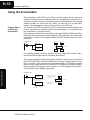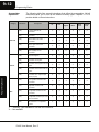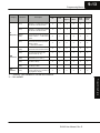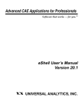
1
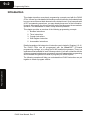
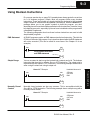
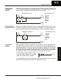
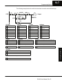
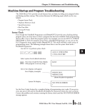
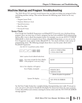
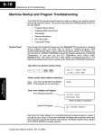
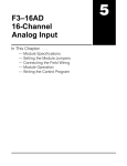
Programming
Basics
In This Chapter. . . .
— Introduction
— Using Boolean Instructions
— Using Timers
— Using Counters
— Using the Accumulator
19
9--2
Programming Basics
Introduction
This chapter describes some basic programming concepts used with the DL305
CPUs. It doesn’t provide detailed information on each instruction, but instead shows
how you can use the most basic elements of the instruction set. If you have quite a bit
of PLC programming experience, you may already know some of the information.
However, we suggest you at least read the portion that discusses the accumulator
operation. The accumulator is used in many different operations.
This chapter provides an overview of the following programming concepts.
1. Boolean Instructions
2. Timer Instructions
3. Counter Instructions
4. Shift Register Instruction
5. Accumulator Instructions
Programming Basics
Detailed examples of all categories of instructions are included in Chapters 11 & 12.
The DL305 CPUs can be programmed with the DirectSOFT PC-based
programming package, or by using the DL305 handheld programmer. There is a
separate manual available for each of these products. If your are not familiar with the
chosen programming device we recommend you use the appropriate programming
device manual along with this manual to program your DL305 system.
The following examples will help you understand how DL305 instructions are put
together to create a program solution.
DL305 User Manual, Rev. D
Programming Basics
9--3
Using Boolean Instructions
Do you ever wonder why so many PLC manufacturers always quote the scan time
for a 1K boolean program? Simple. Most all programs utilize many boolean
instructions. These are typically very simple instructions designed to join input and
output contacts in various series and parallel combinations. Since the DirectSOFT
package allows you to use graphic symbols to build the program, you don’t
absolutely have to know the boolean equivalents of the instructions. However, it may
be helpful at some point, especially if you ever have to troubleshoot the program with
a Handheld Programmer.
The following paragraphs show how these boolean instructions are used to build
simple ladder programs.
END Statement
All DL305 programs require an END statement as the last instruction. This tells the
CPU this is the end of the program. Any instructions placed after the END statement
will not be executed. (This can be useful in some cases. See Chapter 13 for an
example.)
000
020
All programs must have
and END statement
OUT
END
Simple Rungs
You use a contact to start rungs that contain both contacts and coils. The boolean
instruction that does this is called a Store or, STR instruction. The output point is
represented by the Output or, OUT instruction. The following example shows how to
enter a single contact and a single output coil.
DirectSOFT Example
020
OUT
STR 000
OUT 020
END
END
Normally Closed
Contact
Normally closed contacts are also very common. This is accomplished with the
Store Not or, STRN instruction. The following example shows a simple rung with a
normally closed contact.
DirectSOFT Example
000
Handheld Mnemonics
020
OUT
STRN 000
OUT 020
END
END
DL305 User Manual, Rev. D
Programming Basics
000
Handheld Mnemonics
9--4
Programming Basics
Contacts in Series
Use the AND instruction to join two or more contacts in series. The following
example shows two contacts in series and a single output coil.
DirectSOFT Example
000
001
Handheld Mnemonics
020
OUT
STR 000
AND 001
OUT 020
END
END
Midline Outputs
Sometimes it is necessary to use midline outputs to get additional outputs that are
conditional on other contacts. The following example shows how you can use the
AND instruction to continue a rung with more conditional outputs.
DirectSOFT Example
000
001
Handheld Mnemonics
020
OUT
002
021
OUT
003
022
STR 000
AND 001
OUT 010
AND 002
OUT 021
AND 003
OUT 022
END
OUT
END
Programming Basics
Parallel Elements
You may also join contacts in parallel. The OR instruction allows you to do this. The
following example shows two contacts in parallel and a single output coil.
DirectSOFT Example
000
Handheld Mnemonics
020
OUT
001
END
DL305 User Manual, Rev. D
STR 000
OR 001
OUT 020
END
9--5
Programming Basics
Joining Series
Branches in
Parallel
Quite often it is necessary to join several groups of series elements in parallel. The
Or Store (ORSTR) instruction allows this operation. The following example shows a
simple network consisting of series elements joined in parallel.
DirectSOFT Example
000
001
Handheld Mnemonics
020
OUT
002
003
END
STR 000
AND 001
STR 002
AND 003
ORSTR
OUT 020
END
Quite often it is also necessary to join one or more parallel branches in series. The
Joining Parallel
Branches in Series And Store (ANDSTR) instruction allows this operation. The following example
shows a simple network with contact branches in series with parallel contacts.
DirectSOFT Example
000
001
Handheld Mnemonics
020
OUT
002
STR 000
STR 001
OR 002
ANDSTR
OUT 020
END
END
Comparative
Boolean
In the following example when the value
in counter C600 is equal to the constant
value 1234, output 020 will energize.
C600
K1234
020
OUT
The DL330P also provides Comparative Boolean instructions, but they are greater
than and less than instructions instead of equal and not equal.
DL305 User Manual, Rev. D
Programming Basics
Many applications require comparisons of data values. This is especially true in
applications that use counters. Some PLC manufacturers make it really difficult to do
a simple comparison of a counter value and a constant or register. The DL330 and
DL340 CPUs provide Comparative Boolean instructions that allow you to quickly
and easily solve this problem. Comparative Boolean evaluates two 4-digit values
using boolean contacts. The valid evaluations are equal and not equal.
9--6
Programming Basics
Combination
Networks
You can combine the various types of series and parallel branches to solve most any
application problem. The following example shows a simple combination network.
000
002
005
020
OUT
001
003
004
006
END
Boolean Stack
There are limits to how many elements you can include in a rung. This is because the
DL305 CPUs use an 8-level boolean stack to evaluate the various logic elements.
The boolean stack is a temporary storage area that solves the logic for the rung.
Each time you enter a STR instruction, the instruction is placed on the top of the
boolean stack. Any other instructions on the boolean stack are pushed down a level.
The AND, OR, ANDSTR, and ORSTR instructions combine levels of the boolean
stack when they are encountered. Since the boolean stack is only eight levels, an
error will occur if the CPU encounters a rung that uses more than the eight levels of
the boolean stack.
Programming Basics
All of you software programmers may be saying, “I use DirectSOFT, so I don’t need
to know how the stack works.” Not quite true. Even though you can build the network
with the graphic symbols, the limits of the CPU are still the same. If the stack limit is
exceeded when the program is compiled, an error will occur.
DL305 User Manual, Rev. D
Programming Basics
9--7
The following example shows how the boolean stack is used to solve boolean logic.
000
STR
STR
STR
ORSTR
001
AND 004
020
OUT
002
AND 003
005
Output
ANDSTR
OR
STR 000
STR 001
STR 002
1
1
STR 001
1
STR 002
1
002 AND 003
2
2
STR 000
2
STR 001
2
STR 001
3
3
3
STR 000
3
STR 000
4
4
4
4
5
5
5
5
6
6
6
6
7
7
7
7
8
8
8
8
STR 000
AND 003
ORSTR
AND 004
OR 005
1
001 OR (002 AND 003)
1
004 AND [001 OR (002 AND 003)]
1
NOT 005 OR 004 AND [001 OR (002 AND 003)]
2
STR 000
2
STR 000
2
STR 000
3
3
S
S
3
S
S
8
8
S
S
8
1
Programming Basics
ANDSTR
000 AND (NOT 005 OR 004) AND [001 OR (002 AND 003)]
2
3
S
S
8
DL305 User Manual, Rev. D
9--8
Programming Basics
Using Timers
Timers are used to time an event for a desired length of time. The single input timer
will time as long as the input is on. When the input changes from on to off the timer
current value is reset to 0. Timers normally time in tenth of a second intervals, but you
can turn on Special Relay 770 to change the timers to hundredth of a second
intervals. There is discrete bit associated with each timer to indicate the current
value is equal to or greater than the preset value. The timing diagram below shows
the relationship between the timer input, associated discrete bit, current value, and
timer preset.
001
TMR
T600
K30
Input
001
Timer preset
T600
Timer
0
10
20
30
Programming Basics
T600
Contact
Current
Value
DL305 User Manual, Rev. D
40
50
60
0
020
OUT
9--9
Programming Basics
Using Counters
Counters are used to count events. There are two types of counters.
S Regular Up counters
S Stage counters (used with the RLL PLUS instructions)
The up counter has two inputs, a count input and a reset input. The maximum count
value is 9999. The timing diagram below shows the relationship between the counter
input, counter reset, associated discrete bit, current value, and counter preset.
0
1
2
3
4
5
6
7
8
001
CNT
Up
001
C600
K3
002
Reset
002
Counter preset
CT600
1
Current
Value
2
3
4
0
The stage counter has a count input and is reset by the RST instruction. This
instruction is used with the RLL PLUS instructions. The maximum count value is 9999.
The timing diagram below shows the relationship between the counter input,
associated discrete bit, current value, counter preset and reset instruction.
0
1
2
3
4
5
6
7
8
Up
001
SGCNT
C600
K3
Counter preset
CT600
1
2
3
4
Programming Basics
Current
Value
001
0
RST
CT
DL305 User Manual, Rev. D
9--10
Programming Basics
Using the Accumulator
Copying Data to
and from the
Accumulator
The accumulator in the DL305 series CPUs is a 16 bit register which is used as a
temporary storage location for data being copied or manipulated in some manor. For
example, you have to use the accumulator to perform math operations such as add,
subtract, multiply, etc. Since there are 16 bits, you can use up to a 4-digit BCD
number. The accumulator is reset to 0 at the end of every CPU scan.
The Data Store (DSTR) and Data Out (DOUT) instructions and their variations are
used to copy data from a register location to the accumulator, or to copy data from
the accumulator to a register location.
In the following example, when input 000 is on the value (7502) in R402 and R403 is
loaded into the accumulator using the Data Store (F50) instruction. The value in the
accumulator is output to data registers R404 and R405 using the Data Out (F60)
instruction.
DirectSOFT Display
000
DSTR (F50)
R 402
R 403
R 402
7
0
2
2
Accumulator
0
2
5
7
DOUT (F60)
R 404
7
5
0
5
R405
R404
You probably noticed it took two registers to hold a 4-digit BCD number. This is
because each BCD digit requires four binary bit positions.
Programming Basics
Since the accumulator is 16 bits and register locations are 8 bits, there are variations
of the DSTR and DOUT instructions that allow you to copy a single register, or even
half of a register (4 bits) either to or from the accumulator. The following example
shows how you could use the DSTR3 and DOUT2 instructions to copy the lower 4
bits from register 5 to the upper 4 bits of register 16. (These registers correspond to
I/O points and Control Relays respectively.)
DirectSOFT Display
000
DSTR3 (F53)
R 005
Load the lower 4 bits in
register 5 into the lower 4 bits
of the accumulator
DOUT2 (F62)
R 016
Output the lower 4 bits of the
accumulator to the upper 4
bits of R16
DL305 User Manual, Rev. D
R005
The upper 4 bits (*) of R5
are not loaded into the
accumulator
0
0
The upper 4 bits (*) of R400
are not altered
*
8
0
8
8
*
R016
Accumulator
Programming Basics
Changing the
Accumulator Data
9--11
Instructions that change or manipulate data in some way also use the accumulator.
The result of the change resides in the accumulator. The original data that was being
changed is cleared from the accumulator. In the following example, when input 000
is on the value in R000 and R010 is loaded into the accumulator using the Data Store
5 (F55) instruction. The bit pattern in the accumulator is shifted to the left 4 bit
positions using the Shift Left (F80) instruction. Notice how the result resides in the
accumulator. The value in the accumulator is copied to data registers R404 and
R405 using the Data Out (F60) instruction.
DirectSOFT Display
000
R 010
R 000
6
3
9
5
DSTR5 (F55)
R 000
Load the value in registers R0
and R10 into the accumulator
7
6
0
1
I/O Points 100--107
5 4 3 2 1 0
1
0
1
0
15 14 13 12 11 10 9
Acc.
1
0
0
1
S S
Shifted out of
accumulator
SHFL (F80)
K4
0
1
0
0
1
7
6
0
0
I/O Points 000--007
5 4 3 2 1 0
1
1
0
1
0
1
S S
8
7
6 5
4 3
2
1
0
1
0
1
1
0
0
0
0
0
Shift the value in the
accumulator 4 bits to the left
776 will be ON after the shift
777 will be OFF after the shift
9
DOUT (F60)
R 404
Copy the value in the
accumulator to registers R404
and R405
3
R 405
5
0
R 404
776
Shifted a “1” out of Accumulator
777
DL305 User Manual, Rev. D
Programming Basics
Accumulator equals zero after shift
9--12
Programming Basics
Accumulator
Operations
The following table lists several instructions that utilize the accumulator. Not all
instructions allow you to use all the different memory types. Chapters 11 & 12
provide details on these instructions.
Memory Areas
Category
Data Load
Mnemonic
Programming Basics
I/O
CRs
Data
Register
Current
Values
4-digit
BCD
Const.
Shift
Register
Coils
DSTR
(F50)
Load a 4-digit constant or a 2-bytes
of register data into the
accumulator
P
P
P
P
P
P
DSTR 1
(F51)
Load 1-byte of register data into the
accumulator
P
P
P
P
DSTR 2
(F52)
Load the upper 4 bits of a register
into the lower 4 bits of the
accumulator
P
P
P
P
DSTR 3
(F53)
Load the lower 4 bits of a register
into the upper 4 bits of the
accumulator
P
P
P
P
DSTR 5
(F55)
Load the digital values of 16 I/O
points (2 bytes) into the
accumulator
P
DOUT
(F60)
Write the accumulator to 2
sequential registers
P
P
P
P
P
P
DOUT 1
(F61)
Write the lower byte of the
accumulator to a register
P
P
P
P
DOUT 2
(F62)
Write the lower 4 bits of the
accumulator to the upper 4 bits of a
register
P
P
P
P
DOUT 3
(F63)
Write the lower 4 bits of the
accumulator to the lower 4 bits of a
register
P
P
P
P
DOUT 5
(F65)
Write the contents of the
accumulator to a 16-point output
module (2 bytes)
P
P
P
P
CMP
(F70)
Compare a 2-byte BCD reference
or a 4-digit BCD constant to the
accumulator
P
P
P
P
P
P
ADD
(F71)
Add a 2-byte BCD reference or a
4-digit BCD constant to the
accumulator
P
P
P
P
P
P
SUBTRACT
(F72)
Subtract a 2-byte BCD reference or
a 4-digit BCD constant from the
accumulator
P
P
P
P
P
P
MULTIPLY
(F73)
Multiply a 2-byte BCD reference or
a 4-digit BCD constant by the value
in the accumulator
P
P
P
P
P
P
DIVIDE
(F74)
Divide the accumulator by a 2-byte
BCD reference or a 4-digit BCD
constant
P
P
P
P
P
P
Data Out
Math
Description
— Memory Type available for use with the instruction
X — Not available
P
DL305 User Manual, Rev. D
Programming Basics
9--13
Memory Areas
Category
Bit
Manipulation
Data
D
t
Conversion
Fault
Detection
Mnemonic
Description
I/O
CRs
Data
Register
Current
Values
4-digit
BCD
Const.
Shift
Register
Coils
DAND
(F75)
Performs a bit “AND” on a 2-byte
reference or a 4-digit BCD constant
and the bits in the accumulator
P
P
P
P
P
P
DOR
(F76)
Performs a bit “OR” on a 2-byte
reference or a 4-digit BCD constant
and the bits in the accumulator
P
P
P
P
P
P
SHIFT
RIGHT
(F80)
Shifts the contents of the
accumulator to the right a specified
number of times. 1 -- 15 bits can be
shifted.
SHIFT LEFT
(F81)
Shifts the contents of the
accumulator to the left a specified
number of times.
1 -- 15 bits can be shifted.
DECODE
(F82)
Decodes the first 4 bits of the
accumulator into a decimal number.
ENCODE
(F83)
Encodes an accumulator bit into a
4-bit code that represents the
decimal number (0--15).
INV
(F84)
Logically inverts the contents of the
accumulator (1 to 0, 0 to 1).
BCD--BIN
(F85)
Converts the accumulator value
from BCD to Binary
BIN--BCD
(F86)
Converts the accumulator value
from Binary to BCD
FAULT
(F20)
Sends a 4-digit BCD number, from
a 2-byte reference or a constant, to
the programmer display
— Memory Type available for use with the instruction
X — Not available
P
Programming Basics
DL305 User Manual, Rev. D