1
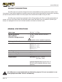
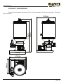
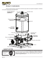
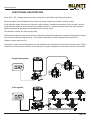
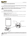
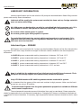
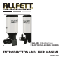
ALL-600 Industrial type ELECTRICAL GREASE PUMPS INTRODUCTION AND USER MANUAL VERSION 2.00 www.allfett.net INTRODUCTION All industrial machinery, equipments and vehicles are working under abrasive operating conditions. The wear between frictional parts become the most highest level at these conditions. Machinery expose bad weather, dust, dirt, rain, snow and heavy weight in most cases. Consequently unwanted breakdowns occur and by that way productivity loss is inevitable. Using automatic lubrication system only increase your profitability. ALLFETT completely take over the work load spend on lubrication with a system which is bringing togather a pump, control unit, distributors, tubes and couplings. Lubrication work is done by ALLFETT centralized lubrication systems in efficient time of machinery or vehicle which is while operating. Lubrication is important for all frictional parts but using correct lubrication system and method only protect parts from wearing for a long time. Feeding lubrication points with correct dosage of lubricant at certain intervals while machinery is operating, provides lubricant film in place longer between parts. By ALLFETT lubrication systems life time of parts on your machinery and vehicles will be increased. ABOUT MANUFACTURER With over 25 years experience of manufacturing Centralized Lubrication Systems ALLFETT is able to provide a wide professional approach to select the correct Centralized Lubrication System for industry and heavy machinery. A highly accurate manufacturing process is involved in producing Centralized Lubrication Systems in order that systems meet the very tight quality procedures and state of the art processes are employed. ALLFETT is among the few companies whose products meet the exact technical and quality standards for a correct central lubrication. We present our high quality and advanced product design concept to our worldwide costumers through our strong brand. ALLFETT creates new opportunities and innovative solutions. As a result of the satisfaction of our customers with our good quality lubrication systems we are continuing in growing in the local and international market and became one of the successful companies in the field. WARNINGS Symbols and words shown below are meant to warn a particular risk to persons, material assets, or the environment. Please carefuly read this manual before installing. Failure to follow the instructions and safety precautions in this manual could result in serious injury or property damage. Caution Prohobition PAGE 1 Notice Electricity www.allfett.net CONTENTS INTRODUCTION Page 1 CONTENTS Page 2 PRODUCT DESCRIPTION Page 3 PRODUCT DIMENSIONS Page 4 PRODUCT COMPONENTS Page 5 FUNCTIONAL DESCRIPTION Page 6 SECURITY VALVE DESCRIPTION Page 7 LUBRICANT INFORMATION Page 8 PUMP FILLING DESCRIPTION Page 9 ELECTRICAL CONNECTIONS Page 10 - 11 RULES TO COMPLY WHILE USING AND WARRANTY CONDITIONS Page 12 PUMP MAINTENANCE Page 13 ORDER INFORMATION Page 14 WARRANTY Page 15 WARRANTY CONDITIONS Page 16 Page 2 www.allfett.net PRODUCT DESCRIPTION ALL-600 pumps are specially designed to meet recomendation of high grease flow needs in dual line systems. Pump element operates as a piston pump and sends pressurized grease to single outlet. Operating principle of pump element allows ALL-600 pumps to be reliable and durable in long life time. ALL-600 pump standard type equipped with a filling coupling with filter to avoid contamination of grease. Security relief valve allows to discharge grease when lubrication lines are blocked. Optional type pumps can equipped with low level indicator systems and two line direction valve. GENERAL SPECIFICATIONS Motor type : 380 V AC - 0,55 Kw Working pressure Max. pressure Direction change pressure : 250 bar. (Factory adjusted pressure) : 1000 bar. : 170 bar. Motor protection class Direction valve is optional equipment : IP 54 Grease class : NLGI NLGI NLGI NLGI NLGI Working temperature : -25°C +80°C Reservoir capacity : 50 Litre Outlet connections : Displacement : (Standard) 144 cm³ / minute (8,5 liters / hour) 00 (-30°C) - (-10°C) 0 (-10°C) - (0°C) 1 (0°C) - (10°C) 2 (10°C) - (30°C) 3 (30°C +) R1/4 (Optional displacement) Displacement of ALL-600 can be adjusted different values optoinally ALL-600 pums are manufactured only lubrication purpose. It is not convenient to run these pumps more than 2 hours continuously. Page 3 www.allfett.net PRODUCT DIMENSIONS Technical drawings below represents the ALL-600 pump models with optional components. Dimension unit is milimeter. 930mm 990mm 510mm 450mm 450mm 470mm Page 4 www.allfett.net PRODUCT COMPONENTS Technical drawings below represents the ALL-600 pump models with optional components. Atandard and optional components described below. Low and High Level indicator system (Optional) Reservoir cover Follower piston (Optional) Reservoir Low Level indicator system (Optional) Filling filter Direction valve (Optional) Filling coupling Manometer (Optional) Return line (Optional) AC Motor Direction valve outlets Chassis Electrical connection Outlet QUALITY SYSTEM ISO 9001 BUREAU VERITAS Certification Page 5 This product is produced by ALLFETT Mekanik ve Elektronik Sistemler San. Tic. Ltd. Sti. company, which, is certificated by Bureau Veritas with certificate to compatible for ISO 9001:2008 standard and owner of the quality management system. www.allfett.net FUNCTIONAL DESCRIPTION Along with AC voltage electrical energy connected to ALL-600 pump filled with grease ; Electrical motor starts to operate when electrical energy sended by electronic control system. Pump element piston vacuums the lubricant inside reservoir. Rotational movement of the eccentric pushes pump element piston so that the lubricant vacoomed before is sended to pump outlet with high pressure. Working pressure of the pump can be adjusted on security valve. The lubricant coming out from pump outlet ; Displacement volume of the pump can be connected to single lubrication point. However displacement volume can also be divided by progressive or 2 line system distributors to feed multiple lubrication points. Optional system control units ; Lubrication system and its components can be controlled and monitored with electronic control cards. Digital sensores and also pressure switches where placed on system components send information to control card. Progressive system 2 line system Page 6 www.allfett.net SECURITY VALVE DESCRIPTION Working pressure is adjusted by security valve on ALL-600 pump body. This security valve directs the grease to reservoir when pressure is increased coused by any blockage. Security valve has also an indicator pin that goes out if pressure is higher than adjusted value. Security valve works as closed circuit. When blockage there is no grease discharge. Only indicator pin comes out and this indicates there is blockage. PRESSURE ADJUSTMENT Security valve is adjusted at 250 bar. pressure by factory default. This pressure can be adjusted to different values by security valve shown below. 1. Cover - To remove cover, turn to counter clockwise, 2. Indicator pin - Pull out the pin 3. Adjustment screw - Pressure is adjusted from this screw. Turning clockwise is increase the pressure. Turning counter clockwise is decrease the pressure. 4. After adjusting pressure, pull in the indicator pin then screw the cover by hand to its place. Indicator pin Security valve Cover Adjustment screw High pressure inside lubrication lines may occur dangareous situations. Because of this reason, before doing any maintenance on lubrication lines make sure the system is not on pressure. Page 7 www.allfett.net LUBRICANT INFORMATION Lubricant specifications can be used with ALL-600 pumps are described below. Before filling reservoir please read carefuly these informations. Lubricant will be used in the system must certainly be clean and any foreign materials must not enter while filling. ALL-600 pumps are designed to use with in centralized lubrication systems only. It is not suitable to use ALL-600 pump for lubricant tranfering or circulation purpose. Do not use rubber based grease in system. Do not use grease types with graphite in system. To remind that lubricants has content which may hazardous to environment. It is important that the county specific regulations and laws on the use and disposal of lubricants must be observed. Lubricant type - GREASE NLGI classes can be used with ALL-1 pumps are described below. Because of the flow characteristics of grease the NLGI class range should be changed at different weather conditions and also temperature differencies. for NLGI 00 grease recomended working temperature is between -30°C and -10°C for NLGI 0 grease recomended working temperature is between -10°C and 0°C for NLGI 1 grease recomended working temperature is between 0°C and 10°C for NLGI 2 grease recomended working temperature is between 10°C and 30°C for NLGI 3 grease recomended working temperature is 30°C and over Keep in mind that the substances of any lubricant are harmfull to environment. Their transport and storage require that special safety measures be taken. Only LITHIUM based and EP additive greases must be used with in system. It is important that the grease will be used must resistant to high pressure. Make sure the liquid grease you are using is EP additive. It should not be forgotten that the grease penetration properties is variable at different environment temperatures. The environmental temperature around lubrication lines must be concidered. Grease properties should be appropriate that environmental temperatures. Changing NLGI classes at diffeerent temperatures is important to correct lubrication. If necessary, high temperature resistant lubricants should be used in some cases. Page 8 www.allfett.net PUMP FILLING DESCRIPTIONS ALL-600 pumps has 2 different optional type. We strongly recomend that the pump must only be filled by filling coupling with filter on pump body. But in some cases, reservoir cover can be removed and then pump can be filled from top of reservoir. Before filling the pump, LUBRICATION DESCRIPTION section on this manual at page10 must be read carefully. 1. METHOD - Filling pump from top of reservoir. Reservoir cover can be disassembled by unscrewing the thumb nuts. After removing thumb nuts, reservoir cover can be removed from its place. After removing cover pump can be filled with grease from top of reservoir. Using this method, environment and also equipment will be used to filling must certainly be clean. Any foreign materials entering while filling damage to pump, distributors and also the equipments. Damages coming from this reason disqualify the warranty. Rezervoir cover Tumb nut Filling coupling with filter 2. METHOD - Filling pump from filling coupling with filter. ALL-600 pump has filling cover on pump body. Filter inside filling cover prevents the entering any dirt or smal particules to pump reservoir. We are strongly recomend that you to use filling coupling to fill pump. Filter inside the filling coupling must be cleaned at certain time intervals. Page 9 www.allfett.net ELECTRICAL CONNECTIONS Pumps have an electric driven motor. Electrical lines must be connected properly as described in schema below. U1 V1 W1 Motor electrical connection (380 V AC ) T S R Any maintenance on pumps under electrical voltage could lead to personal injury. Disconnect all electrical power before any maintenance . Page 10 www.allfett.net ELECTRICAL CONNECTIONS Low level indicator has 2 option as shown on schemas below. It is important that the correct option which is ordered must be connected to pump. Low level indicator options are sold separatelly. It is important that the correct low level option must be connected to pump. Low & High level indicator connection 12 - 24 V DC High level (+) input Low level (+) output Contact connection 12 - 24 V DC 1 2 Low level (+) input 3 High level (+) output Contact connection Low level indicator connection 1 2 Low level (-) 3 Low level signal Low level (+) Any maintenance on pumps under electrical voltage could lead to personal injury. Disconnect all electrical power before any maintenance . Page 11 www.allfett.net RULES TO COMPLY WHILE USING AND WARRANTY CONDITIONS 1. Damages occur while additional transports after delivering the goods from ALLFETT to the customer DISQUALIFIES THE WARANTY. 2. Pumps are produced to lubrication purpose only and are not convenient to work more than 2 hours continuously. Working under maximum pressure more than 2 hours will harm the system. Damages occur from this reason DISQUALIFIES THE WARANTY. 3. Washing of the pump with pressured water causes damage. Any damage occur from this reason DISQUALIFIES THE WARANTY. 4. Pumps have an electric driven motor. Electrical lines must be connected properly as described in PAGE 12 and applied only by qualified and instructed personel. All electrical connections and lines must be checked regularly for damage and to ensure that they are firmly in place. 5. Damages coming from voltage fluctuation, wrong electricity installation, connecting wrong voltage to product DISQUALIFIES THE WARANTY. 6. Keeping an uncovered cable(s) during system assembly may cause fatal damages where high voltage is transformed to low voltage. Lines must be connected properly to prevent personal injury and damage to property. 7. Only proper NLGI class lubricants must be used with in system. NLGI class must be changed according to weather conditions. Use NLGI 0 for cold weather, increase the NLGI class up to 3 towards hot weathers. 8. Only LITHIUM based and EP additive lubricants must be used with in system. 9. Rubber based lubricant types must not be used in the system. Damages or faults occur from this reason DISQUALIFIES THE WARANTY. 10. Lubricant will be used in the system must certainly be clean and any foreign materials must not enter while filling. Any foreign materials, dirt or small particules while filling lead to system units failing and possibly property damage to equipments. Damages or faults occur from this reason DISQUALIFIES THE WARANTY. 11. Pump must be filled from the filling coupling with filter on pump body. Never use top cover to fill pump. Filter inside the filling coupling must be cleaned at certain time intervals. 12. Disassembling or loosing any part while pump working is prohibited. Any damage coming from this reason DISQUALIFIES THE WARANTY. Also any personal injury occur from this reason ALLFETT does not accept responsibility. 13. Another goal of Centralized Lubrication Systems is to protect environment. So it is adviced to fill grease to the systems by mobile or hand pumps. 14. Unouthorized modifications to the units and the use of unouthorized spare parts and aids prohobited and DISQUALIFIES THE WARANTY. Only maintenance may apply descibed in PAGE 14 - 15. ALLFETT Technical Service must be informed to any other possible troubles and necessary procedures must be performed. 15. ALLFETT Mekanik ve Elektronik Sistemler SAN. TIC. LTD. STI and ALLFETT Pazarlama ve Dis Ticaret LTD. STI. does not accept responsibility for damages described in items above on equipments which ALLFETT systems are installed. Page 12 www.allfett.net PUMP MAINTENANCE 1. If pump not starts ; a. Electrical connections of the pump may be loosen or broken. Check the electrical cables and connections of the system according to schemas on page 12. b. Connected electricity to pump may different then AC voltage. Connect the electricity 380 V AC which is shown on motor sticker. Pump has low level indicator ; c. Control unit (PLC or ALLFETT control system) may give failure and stops the pump because of the grease inside pump decreased under minimum level. Fill the reservoir according to items 10, 11, 12, 13, 14, 15 and 16 in RULES TO COMPLY WHILE USING AND WARRANTY CONDITIONS. d. If ALLFETT control system is connected the system ; e. Electronic control card may be in waiting period. Wait until working time starts. If necessary control card pass to working period by pressing ADDITIONAL CYCLE button. 2. If pump starts but not sending grease ; a. Grease inside pump decreased under minimum level. Fill the reservoir according to items 10, 11, 12, 13, 14, 15 and 16 in RULES TO COMPLY WHILE USING AND WARRANTY CONDITIONS. b. Pump may take air due to work without grease ; Remove connected coupling from pump outlet. Start to operate pump. Pump should run contiuously untill grease without air is seen from pump outlet. When the grease without air seen from pump outlet, coupling must be tightened to outlet again With this process pump is now ready to send grease to lubrication point. Grease coming out from end point of lubrication line may take long time according to line length. Unouthorized modifications to the units and the use of unouthorized spare parts and aids prohobited and disqualify the warranty. TECHNICAL SERVICE Page 13 www.allfett.net ORDER INFORMATION Product name ALL-600 pump with low&high level and follower piston ALL-600 pump with low level Order number 10 60 38 5A 10 60 38 5S SALES Page 14 www.allfett.net WARRANTY Utilisation of this warranty certificate has been permitted by The Republic of Turkey, The Ministry of Industrial and Commerce, The general Administration of Protection of Consumer Right and Competition, in accordance with the law numbered 4077 . PRODUCER COMPANY NAME : ALLFETT Mekanik ve Elektronik Sistemler San. ve Tic. Ltd. Þti. CENTRAL ADRESS : Yeni Eyup Bulvari, Topcular Cad. Set Ustu, No:1 DemirkapýRami / Ýstanbul TELEPHONE : 0212 501 32 01 (PBX) FAX : 0212 501 33 37 AUTHORISED PERSON SIGNATURE - STAMP : : PRODUCT TYPE : Electrical grease pump BRAND : ALLFETT MODEL : ALL-600 (With low level) SERIAL NUMBER ALL-600 (With low&high level) : ................................... DELIVERY DATE / PLACE : ................................... WARRANTY : 2 years REPAIR TIME : 30 days SALER COMPANY NAME : ................................... CENTRAL ADRESS : ................................... TELEPHONE : ................................... FAX : ................................... BILL DATE / NUMBER : ................................... Page 15 www.allfett.net WARRANTY CONDITIONS 1. 2. 3. 4. 5. 6. 7. The warranty period is two years from the date of delivery. The product including all its components is under the warranty of our company. In case of defects within the warranty period the period spent in repairing is added to the warranty period. The repairing period is maximum 30 days. This period starts from the date of delivery of the product to the services centers or to the seller, the agency the representative, the importer or the manufacturer of the product respectively, in case there are service centers. In case the product has material, workmanship or manufacturing defects, the product will be repaired free of charge and expenses of any sort including labor, the value of the parts replaced or any our charges. The product will be replaced free of charge; - If the product permanently disfunctions due to repeating the same defect more than four times within the warranty period - If the maximum period for repairing is exceeded. - If it is determined that the defect cannot be repaired by report written by the service, or in the absence of service centers, by the seller, agency, representative, importer or manufacturer of the product respectively. The present warranty does not cover damages resulting from importer handling by deviating from the instructions in the manual. General administration of protection of consumer rights and competition in the ministry of industry and commorce may be applied for problems concerning the warranty certificate. Page 16 www.allfett.net DANGEROUS OR HARMFUL CONDITIONS TO ENVIRONMENTAL AND HUMAN HEALTH DURING USE All ALLFETT systems are producing according to relevant provisions of security regulations. There is no risk for environmental and human health during use. TRANSPORT AND STORAGE There are no restrictions on transportation by land, air and sea. In general, products should be stored in a dry and dust-free environment. The storage temperatures are between -10°C and +40°C. All products are packed with paper based support matarial to reduce damage. Upon receiving the package please check the items for possible damage. Page 17 www.allfett.net NOTES Page 18