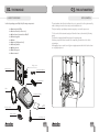
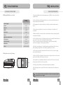
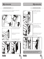
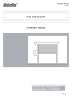
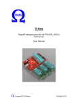
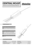
1
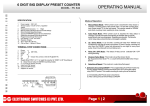
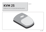
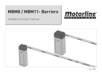
KVM 25
OPERATION MANUAL / INSTALLER
v1.0
REV. 06/2014
00. CONTENTS
01. SAFETY INSTRUCTIONS
▷ INDEX
STANDARDS TO FOLLOW ◁
ATTENTION:
00. CONTENTS
▷ index | page 01.A
▷ To ensure the safety of people, it is important that you read all the following
instructions.Incorrect installation or incorrect use of the product can cause physical
injury and material damage.
▷ Keep these instructions in a safe place for future reference.
▷ This product was designed and produced strictly for the use indicated in this
manual. Any other use, not expressly indicated here, could compromise the good
condition/operation of the product and/or be a source of danger.
▷ ELECTROCELOS SA is not responsible for the improper use of the product,
or other use than that for which it was designed.
▷ ELECTROCELOS SA is not responsible if safety standards were not taken
into account when installing the equipment, or for any deformation that may occur to
it.
▷ ELECTROCELOS SA is not responsible for the safety and proper operation
when using components not sold by them.
▷ Do not make any modifications to the operator components and / or their
accessories.
▷ Beffore installation unplug the automatism from the source of power.
▷ The installer must inform the client how to handle the product in case of
emergency and provide this manual to user.
▷ Keep remote controls away from children, to prevent the automated
system from being activated involuntarily.
▷ The customer shall not, under any circumstances, attempt to repair or tune
the operator .Must call qualified technician only.
▷ Connect the automatism to a 230V plug with ground wire.
▷ Operator for outdoor and indoor use.
01. SAFETY INSTRUCTIONS
▷ standards to follow | page 01.B
02. THE PACKAGE
▷ inside the package | page 02.A
03. THE AUTOMATISM
▷ Lock / Unlock | page 02.B
▷ technical specifications | page 03.A
04. INSTALLATION
▷ pre-installation info | page 03.B
▷ automatism installation | page 04.A
▷ installation map | page 05.B
05. PROGRAMMING
▷ programming the limit switches | page 06.A
▷ description | page 07.A
▷ programming dip switches | page 07.A
▷ adjusting potentiometers | page 07.B
▷ programming transmitter | page 07.B
▷ reset control board’s memory | page 07.B
06. CONNECTION SCHEME
▷ connecting components to the control board | page 08.A
01.A
01.B
02. THE PACKAGE
03. THE AUTOMATISM
▷ INSIDE THE PACKAGE
LOCK / UNLOCK ◁
The automatism unlock function allows the user to open and close the gate manually,
without having to remove the motor from the installation site.
This funcionality is specially important in emergency cases and/or power cuts.
Inside the package you will find the following components:
▷
▷
▷
▷
▷
▷
▷
▷
▷
▷
01 automatism KVM25
01 control board (inside motor)
02 four channel transmitters MX4SP
01 mounting plate
01 chain
01 pinion for Ø25mm shaft
01 bearing bracket
04 fixing screws
01 unlocking cord
01 user manual
To lock or unlock the automatism just pull down the lever as shown in the following
image.
The lever has a spring that will bring it up to the starting point.
Each time you pull the lever down and rise completely, you will unlock or lock the
automatism.
When pulling down, a small sound of gears engaging means that the lock/unlock was
successfully performed.
Fixing screws
Mounting plate
Transmitters MX4SP
Control Board
Chain
Automatism KVM25
Pinion for shaft
User
manual
Bearing bracket
unlocking cord
02.A
02.B
03. THE AUTOMATISM
04. INSTALLATION
▷ TECHNICAL SPECIFICATIONS
PRE-INSTALLATION INFO ◁
KVM25 specifications are as follow:
For a proper installation and a durable performance of KVM25, be aware of the following parameters:
▷ Please read all steps of this manual at least once, so that you know the full process
before starting the real assembling.
KVM25
AC 230V 50/60Hz
▷ Power Supply
80W
▷ Power
8A
▷ Current
▷ RPM
▷ Please make sure that the door’s structure is solid and in good conditions to be
automated.
20 RPM
▷ Noise level
<65dB
▷ Force
▷ Make sure that the sectional door has no mechanical anomalies, they may affect the
automatism’s durability .
30N
-30°C a 65°C
▷ Operating temperatures
100W
▷ Transformer
▷ Protection class
IP20
30ciclos / h
▷ Work Rate
▷ Fuses
▷ This equipment can only be installed on sectional doors with a maximum area of
18m2.
220V 1A - 24V 10A
▷ To check if the door is in good condition for the motor to be installed, manually raise it
to 800mm, 1600mm and 2000mm from the floor and drop it.
The door must remain suspended in that position or going down very slightly.
If this does not happen, check the springs condition.
▷ Check the surrounding space. Carefully evaluate potential dangers that can cause
physical damage and possible contact with bugs, infiltrations or others.
▷ Please make sure that the automatism will be connected to a 230V power supply,
protected with earth wire.
KVM25 dimensions are the following:
▷ Please check if there is apropriate electronic protection against short-circuits/current
peaks, and earth wire on the main electric board.
110mm
186mm
▷ Be carefull in case of manually operating the control board. The incorrect usage can
damage some sensible electronic components.
▷ Check if you have all the necessary material ready for the installation.
▷ Check all safety devices to install. This will ensure that unexpected accidents won’t
happen.
320mm
It is very important that before installation, make sure the springs are adjusted
according to the door’s weight!
03.A
03.B
04. INSTALLATION
04. INSTALLATION
▷ AUTOMATISM INSTALLATION
AUTOMATISM INSTALLATION ◁
In the illustrated diagrams below and on the following page, are represented the
procedures for proper installation of the motor KVM25.
↑ 01 - Place the pinion on the Ø25mm
spring’s shaft of the sectional door.
← 02 - Place the chain over the pinion
leaving it hanged.
← 04 - Slightly loosen the bearing
bracket’s screws (left),to be able to
move it sideways.
← 05 - Pull the metal plate to the wall
and secure with the screws.
After fixing the plate, tighten the
bearing bracket’s screws back to fix it
too.
↓ 06 - Pull the pinion to the bearing and
tighten the two bolts to secure the
pinion to the shaft.
↓ 03 - Pass the Ø25mm shaft through
the bearing on the support plate .
It is very important that these quotas are respected! Only in this way the
correct functioning and durability of automatism can be assured!
04.A
04.B
04. INSTALLATION
04. INSTALLATION
▷ AUTOMATISM INSTALLATION
INSTALLATION MAP ◁
06
02
04
03
↑ 07 - Place the automatism on the support plate (left), and assemble the chain on the
motor’s pinion as you can see on the right image.
Place the screws on the motor in order to support it on the metal plate, without
tightening them completely, so that you are able to adjust the automatism.
01
05
02
LEGEND:
01 ▷ motor KVM25
02 ▷ support plate
03 ▷ chain
04 ▷ pinion for Ø25mm shaft
05 ▷ bearing bracket
06 ▷ Ø25mm sectional door’s shaft
01
↑ 08 - With the bolts still loose, pull the engine down in order to tighten the chain.
While pulling down, fasten the 4 motor bolts to secure it on the support plate. The
automatism is now installed.
05.A
05.B
05. PROGRAMMING
05. PROGRAMMING
▷ PROGRAMMING LIMIT SWITCHES
PROGRAMMING LIMIT SWITCHES ◁
In the illustrated diagrams below and on the following page are represented the
procedures for proper programming of the motor KVM25 limit switches, once installed
on the gate.
01 - Unlock the motor, pulling the lever
down. You will hear a little click when
pulling down, and then you must let the
lever go up.
02 - Open the automatism cover with a
screwdriver and connect the motor to a
power source at 230V.
05 - Move the close magnetic actuator
near the sensor until the red LED lights up.
This indicates that the limit switch will
activate in that exact position.
06 - Manually move the door to the
open position.
03 - Slightly loosen the 4 screws of the
magnetic actuator.
04 - Manually pull the door into the closed
position.
07 - Move the opening magnetic actuator
near the sensor until the red LED lights up.
This indicates that the limit switch will
activate in that exact position.
Now tighten the 4 screws of the magnetic
actuator.
08 - Lock the motor and test the door
opening and closing using either the
"PUSH" button on the control board or the
transmitter. If necessary, repeat the
previous steps, from the image 03, to
better tune the limit switches.
It is very important that these quotas are respected! Only in this way the
correct functioning and durability of automatism can be assured!
06.A
06.B
05. PROGRAMMING
05. PROGRAMMING
POTENTIOMETERS AJUSTMENT ◁
▷ DESCRIPTION
▷ MOTOR INSTALLED ON LEFT SIDE:
6A▷ This potentiometer adjusts the
motor’s power when closing
6B▷ This potentiometer adjusts the
motor’s power when opening
▷ MOTOR INSTALLED ON RIGHT SIDE:
1A
2A
1B
3A
2B
3B
4
5
CONTROL BOARD
6A
6B
7
8
9
01 ▷ Battery Input (A - Positive | B - Negative)
02 ▷ Transformer Input
03 ▷ Motor Cable Input (A - Black | B - Red)
04 ▷ Dip-Switches
05 ▷ Connector J5
06 ▷ Force ajusting potentiometers
07 ▷ Button “PUSH”
08 ▷ LED “LEARN”
09 ▷ Button “LEARN” (programming button)
6A
6B
TRANSMITTER PROGRAMMING ◁
1▷ Click once on the LEARN button and
the LEARN LED will light up.
2▷ Press once on the transmitter’s button
you wish to operate. The LED will flash
three times, indicating successful
programming.
NOTE: To program multiple transmitters,
repeat the same steps for each transmitters.
▷ DIP-SWITCHES
ON (UP)
6A▷ This potentiometer adjusts the
motor’s power when opening
6B▷ This potentiometer adjusts the
motor’s power when closing
[MXS4SP]
[MX4SP]
OFF (DOWN)
Dip 1
Automatism is installed on the
Automatism is installed on the left of
right of the gate (seen from inside). the gate (seen from inside).
Dip 2
Enable automatic closing.
(Pause time 1 minute fixed)
RESET CONTROL BOARD’S MEMORY ◁
1▷ Press and hold the LEARN button for eight seconds.
The LEARN LED will flash three times, indicating the success of the operation.
Disable automatic closing.
07.A
07.B
06. CONNECTION SCHEME
▷ CONNECTING COMPONENTS TO CONTROL BOARD
LED POWER
LEARN
1
2
3
4
5
VR1
VR2
LED
LEARN
12
ON
Battery
Transf.
PUSH
V+ INFRD GND PUSH GND
CONNECTOR 2 ( INF ) - Works without
photocells, not needing shunt.
CONNECTOR 1 ( v+ ) - 15 VDC 1.5W máx.
Motor
Wall
button
Photocells MF1
DV 12/24V
DV 12/24V COM NC
~ ~
~ ~
08.A