1
6 DIGIT BIG DISPLAY PRESET COUNTER
OPERATING MANUAL
MODEL : PC 642
SPECIFICATION:
Modes of Operation:
1.
2.
1.
Manual Reset Mode : When preset count is reached the relay status is
changed. Counting stops at the preset value. To start the counting from
zero, press switch 'E' on the front paneI. The counter resets to '000000'
and starts counting. Here resetting is done manually.
2.
Auto Reset Mode: When preset count is reached the relay status is
changed. Counter will reset automatically to '000000' after a specific
preset time & start counting again. Resetting is automatic. The time for
which relay status should remain unchanged is settable
3.
Up / Down Mode: In Up Counter, counting will start from '000000' and
increment by one digit for every input pulse. In Down Counter, counting will
start from the PRESET value and decrement by one digit for every input
pulse. Down Counting will not count below zero.
4.
Relay ON / OFF Mode : The status of relay can be selected ON / OFF
during counting.
5.
Division Factor Mode: This mode is to set the division factor.
Eg: Suppose division factor = 4. i.e. count will increment after every 4 input
pulses.
6.
Selection of Speed : This mode is to select slow/fast speed.
Power supply : 230 V AC.
Sensor supply: In-built 12 V D.C. regulated
supply.
3. Measurement accuracy : + / - 1 Digit.
4. Memory backup facility to store count and settings.
5. Micro Controller based technique.
6
Input from PNP/NPN sensors & micro \limitswitch.
7. Reset from front panel & from terminal strip.
8. Programming through front panel.
9. LED display- 1 inch red colour.
10. Readout- 6 digits.
11. Size- 190 X 90 X 96 mm.
12. Cut out Size – 186mm X 90mm
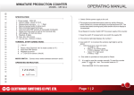
TERMINAL STRIP CONNECTIONS:
1.
2.
3.
4.
5.
6.
7.
Phase
Neutral
Earth
NC
C
NO
8.
9.
10.
11.
(+) 12 V DC for sensor (In-built).
Input from PNP sensor.
Input from NPN sensor.
Negative for sensor.
Output relay contact, rated at 5A @230V AC
Reset (Short PIN 7 & 11 to reset the counter to “0000” in UP Counting or
to show the set value in DOWN Counting mode)
7. Selection of Counting ON/OFF: This is applicable to Auto Reset mode only.
This is to select whether counting should be ON or OFF during the output
relay ON/OFF period. This means counting for next cycle can be started.
Sensor PNP O/P
P
N
NC
C
NO
Rst. +VE
Contactor Coil
230 V AC
Phase
a) Immediately after Preset value is reached or,
b) After a time period for which Relay is ON/OFF
PNP NPN
-VE
Sensor NPN O/P
Neutral
Page 1 | 2
6 DIGIT BIG DISPLAY PRESET COUNTER
MODEL : PC 642
Four Switches are provided on key pendent
for settings.
M : It is used to enter into menu mode or to
set the preset value
: It is used to shift the digit at right side
: It is used to increment the blinking digit
: It is used to reset the counter manually or
E
to set the program
PRESET VALUE SETTING :
To set the preset value proceed as below :
a) Press 'M' switch for 3 seconds.
E
M
b) After 3 seconds out of the 6 digits, first digit starts
blinking.
c) Use switch to increment the blinking digit.
d) Use switch to shift between 1 st and 6 th digits.
In this way the preset value can be set
Press 'M' switch to set Decimal Point for Preset Value.
In this menu preset value is shown on display which is earlier set & DOT is
blinking at last set position. To change Dot position use switch.To Store the
preset value press ‘E’ Switch
TO SET THE VARIOUS 7 MENUS PROCEED AS FOLLOWS:
1) SWITCH OFF THE POWER SUPPLY OF THE COUNTER
2) KEEP THE SWITCH “M” PRESSED AND NOW SWITCH 'ON' THE SUPPLY. .IT WILL
DISPLAY LAST COUNT ,AND ENTER INTO MENU IF ONLY “M”
SWITCH IS PRESSED FOR 1 SEC WHILE POWER ON.
MENU 1: This menu is to set Manual / Auto Reset Mode.
a) The extreme left digit displays the menu number 1
b) For Auto Reset : Extreme right digit displays 2
c) For Manual Reset : Extreme right digit displays 1
d) To change the status use
switch.
To change to n ext menu press 'M' switch.
MENU 2: This menu is to set time delay for Auto Reset Mode.
a)The extreme left digit displays the menu number 2.
b) The 3 extreme right digit indicates time delay.
c) Use
switch to select any of the three digits.
d) Use switch to increment the selected digit to set the time.
00.1 sec - Minimum time delay.
99.9 sec - Maximum time delay.
Display indicates the time delay for which relay should remain ON/OFF in Auto
Reset Mode.To change to next menu press 'M' switch.
OPERATING MANUAL
MENU 3: This menu is to select UP or DOWN counting.
a) The extreme left digit displays the menu number 3.
b) Up Counting - Extreme right digit displays 1.
c) Down Counting - Extreme right digit displays 2.
d) To change the status use switch.
To change to next menu press 'M' switc h.
MENU 4:This menu is to select Relay Status ON or OFF during counting.
a) The extreme left digit displays the menu number 4.
b) Relay ON - Extreme right digit displays 2.
c) Relay OFF - Extreme right digit displays 1.
d) To change the status use switch.
To change to next menu press 'M' switch.
MENU 5: This menu is to set the division factor.
We can set maximum division factor upto '99'
using shift and increment
switch.
For eg : Suppose we set the division
factor = 4. After every 4 pulses count increments. If we press 'M' switch it will
st
enter into 1 menu & the cycle continues .
To change to next menu press 'M' switch
MENU 6:: This menu is to select slow/fast speed.
a) The extreme left digit displays the menu number 6
b) Use
switch to increment the extreme right digit to set
the speed .
1 - Select this if input is from limit switch.
IF RPM is < 100
2 - Select “2” for medium speed.
IF RPM in Between 100 to 1000
3 - Select “3” for high speed.
IF RPM is >1000
To change to next menu press 'M' switch
MENU 7:This menu is to select Counting ON/OFF during Auto Reset Delay.
a) The extreme left digit displays the menu number 7
b) Use switch to increment the extreme right digit to
select ON/OFF .
1 - Counting OFF
2 - Counting ON.
TO STORE SETTINGS & BEGIN COUNTING PRESS 'E' SWITCH.
PRESS 'E' SWITCH TO RESET THE COUNTER AND TO START NEXT
CYCLE.
Page 1 | 2