1
US 20080164318A1
(19) United States
(12) Patent Application Publication (10) Pub. No.: US 2008/0164318 A1
Wulff et al.
(54)
(43) Pub. Date:
RE-CONFIGURABLE TRIGGER ASSEMBLY
(75) Inventors:
continuation of application No. 10/160,772, ?led on
Jun. 3, 2002, noW Pat. No. 7,055,749.
Publication Classi?cation
Thomas Wulff, North Patchogue,
NY (U S); Azer Ilkhanov,
Brooklyn, NY (U S)
Jul. 10, 2008
(51) Int- Cl
G06K 7/10
(2006.01)
AMIN,
Correspondence
TUROCY
Address:
& CALVIN, LLP
(57)
US. Cl- .................................................
ABSTRACT
..
1900 EAST 9TH STREET, NATIONAL CITY
CENTER, 24TH FLOOR,
CLEVELAND, OH 44114
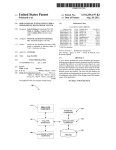
Described is an improved trigger assembly for use in an
electronic device. The trigger assembly includes a pressure
(73)
Assignee;
SYMBOL TECHNOLOGIES,
INC" Holtsville’ NY (Us)
(21)
Appl_ No;
11/950,953
sensitive member and a trigger button. The pres sure sensitive
member includes tWo or more conductive lines. The pressure
sensitive member is secured to a portion of the mobile termi
nal. The trigger button is secured to the mobile terminal in a
manner such that a force applied to the trigger button causes
(22)
Filed:
D e c_ 5, 2007
her. The force applied on the pressure sensitive member
a resultant force to be applied on the pressure sensitive mem
causes a change in an electrical property between at least tWo
.
(63)
.
Related U's'Apphcatlon Data
Continuation of application No. 11/381,558, ?led on
May 4, 2006, noW Pat. No. 7,306,156, Which is a
of the conductive lines. A module measures the electrical
property between the conductive lines. A function of the
device is initiated depending on a Comparison Of the mea
sured electrical property to a threshold value.
Patent Application Publication
Jul. 10, 2008 Sheet 1 0f 5
US 2008/0164318 A1
d.0;
Mm.
Patent Application Publication
Jul. 10, 2008 Sheet 2 0f 5
US 2008/0164318 Al
(\l
U
H
ll
Patent Application Publication
Jul. 10, 2008 Sheet 3 0f 5
US 2008/0164318 A1
3FIG.
Patent Application Publication
Jul. 10, 2008 Sheet 4 0f 5
US 2008/0164318 A1
gl
9 WC‘
3
.
?ll
FIG. 4
Patent Application Publication
Jul. 10, 2008 Sheet 5 0f 5
US 2008/0164318 A1
w" 3 ‘
Q6
Q0
6.1 ‘I
W
FIG. 7
‘ FIG. 6
Jul. 10, 2008
US 2008/0164318 A1
RE-CONFIGURABLE TRIGGER ASSEMBLY
change in the electrical resistance the pres sure sensitive mem
ber. For example, the force causes a conductive layer of the
CROSS-REFERENCE TO RELATED
APPLICATIONS
pressure sensitive member to come in contact With conductive
[0001]
This application is a continuation of US. patent
application Ser. No. 11/381,558, ?led May 4, 2006 and
entitled “RE-CONFIGURABLE TRIGGER ASSEMBLY”,
Which is a continuation of US. patent application Ser. No.
10/ 160,772, ?led Jun. 3, 2002 and entitled, “RE-CONFIG
URABLE TRIGGER ASSEMBLY”. The entireties of these
applications are incorporated herein by reference.
BACKGROUND INFORMATION
[0002] Triggers or buttons are commonly used on elec
tronic devices. For instance, triggers are employed on mobile
traces Within the pressure sensitive member. As the force
increases (Within a certain range), the electrical resistance of
the conductive traces decreases. In another embodiment of
the invention, asserting a force on the trigger button causes a
change in the capacitance of the pressure sensitive member. In
yet another embodiment, a pieZoelectric element is included
in the pressure sensitive member Wherein When pressure is
applied to the pressure sensitive member there is a change in
potential betWeen the opposite sides of pieZoelectric element.
[0007] In a preferred embodiment of the present invention,
at least a portion of the pressure sensitive member is insert
molded into the mobile terminal housing, creating an integral
seal.
[0008]
In another aspect of the present invention, the trig
computing terminals, bar code scanners, cellular phones, por
table digital assistants (PDAs), etc. The trigger is used to
gering system includes a user force adjustment feature
initiate certain functions on the device. For instance, the trig
Wherein a user can adjust the amount of force required to
ger may activate a module to capture bar code information.
activate the trigger.
[0009] In yet another embodiment of the invention, the
triggering system includes a user position adjustment feature,
The module may be a laser based bar code scanner or an
imager. The trigger may also activate a speaker module for
telephonic communication, it may activate a data transfer
function or it may be used to navigate through menu options
Wherein a user can adjust the number of trigger positions, i.e.,
1, 2, or 3 positions, for activation of several different features.
on a display.
[0010]
[0003] FIG. 1 shoWs a typical conventional trigger assem
bly for a mobile terminal. The assembly consists of several
mechanical type components that are utiliZed to actuate elec
trical sWitch assembly 8 upon the depression of a trigger
button 4. SWitch assembly 8 has tWo sWitch elements 811 and
triggering system includes a pressure sensitive member that
includes multiple pressure sensitive target areas Which Would
enable a user to activate several different features by depress
ing different areas of the trigger.
8b to activate tWo functions on the mobile terminal. SWitch
assembly 8 can include contacts 5 or Wires/?ex that connect to
triggering system includes a tactile or audio feedback mecha
nism.
[0011]
In yet another embodiment of the invention, the
In yet another embodiment of the invention, the
circuitry Within the mobile terminal. A trigger housing 9
[0012]
connects trigger button 4 With mobile terminal housing 10. A
the invention Will become better understood With regard to the
These and other objects, advantages and features of
trigger beZel 6 connects trigger button 4 With trigger housing
folloWing description, appended claims and accompanying
9. A leaf spring 3 acts to restore trigger button 4 to its initial
?gures.
position after trigger button 4 is depressed. Sealing in terms of
electrostatic discharge (ESD), Water, and dust, requires the
addition of gaskets to the trigger assembly.
[0004] The above-described trigger assembly has a number
of shortcomings. The trigger assembly requires a user to
assert a ?xed amount of force and stroke in order to activate
the trigger. Also, the trigger assembly must include gaskets to
environmentally seal the terminal. Even With such gaskets,
Water and debris may still enter the terminal. In addition, the
trigger assembly has a limited number of life cycles due to
Wear on the various moving parts. In addition, the trigger
assembly requires a relatively signi?cant amount of labor to
manufacture.
SUMMARY OF THE INVENTION
[0005]
Described is an improved trigger assembly for use in
a mobile terminal or similar device. The trigger assembly
includes a pressure sensitive member and a trigger button.
The pressure sensitive member is secured to a portion of the
mobile terminal. The trigger button is secured to the mobile
BRIEF DESCRIPTION OF DRAWINGS
[0013]
FIG. 1 shoWs a conventional trigger assembly used
in a mobile terminal;
[0014] FIG. 2 shoWs an exemplary embodiment of a trigger
assembly according to the present invention including a por
tion of a housing of a mobile terminal;
[0015] FIG. 3 shoWs an exploded vieW of a trigger assem
bly of a preferred embodiment of the present invention;
[0016]
FIG. 4 shoWs a pressure sensitive member of a pre
ferred embodiment of the present invention;
[0017] FIG. 5 shoWs a side vieW of an alternative embodi
ment of the pressure sensitive member of the present inven
tion;
[0018] FIG. 6 shoWs another alternative embodiment of the
pressure sensitive member of the present invention; and
[0019] FIG. 7 shoWs a side vieW of an alternative embodi
ment of the pressure sensitive member of the present inven
tion.
terminal in a manner such that a force applied to the trigger
button causes a resultant force to be applied on the pressure
DETAILED DESCRIPTION
sensitive member.
[0006] The pressure sensitive member includes a connector
that is coupled to circuitry on the mobile terminal. The asser
tion of a force on the trigger button changes electronic prop
assembly. The triggering assembly includes a trigger button
erties of the pres sure sensitive member. In one embodiment of
the invention, asserting a force on the trigger button causes a
14 and a pressure sensitive member 20. A trigger housing 19
connects trigger button 14 With mobile terminal housing 10.
[0020]
FIG. 2 shoWs a portion of a mobile terminal housing
10 having a triggering assembly according to the present
invention. FIG. 3 shoWs an exploded vieW of the trigger
Jul. 10, 2008
US 2008/0164318 A1
Trigger housing 19 is preferable comprised of a rubber over
mold. Trigger button 14 is secured to trigger housing 19 via an
interface ?t or other fastening techniques knoWn to those of
skill in the art. Trigger button 14 includes a front section 17
for engagement With one or more of the user’s ?ngers. Oppo
site front section 17 of trigger button 14 is a back section 18.
When a user engages trigger button 14, back section 18
asserts a force on trigger housing 19 Which asserts a force on
a target area 22 of pressure sensitive member 20. In an alter
native embodiment of the invention the trigger button could
directly assert the force on the target area of the pressure
sensitive member.
and 36 improves (decreasing the electrical resistance). As a
result, as the pressure applied to pressure sensitive member 20
increases, the current ?oW betWeen conductive traces 35 and
36 increases (Within a certain range of pressure).
[0024] Connector 26 is fastened to a terminal connector 7
Within the mobile terminal. Circuitry Within the mobile ter
minal measures the current betWeen conductive traces 35 and
3 6. In one embodiment of the invention, the measured current
is compared to a threshold value. If the measured current
betWeen conductive traces 35 and 36 is more than the thresh
terminal housing 10. The techniques for molding pressure
old value, a certain function of the mobile terminal is acti
vated. For instance, if the measured current exceeds the
threshold value, the mobile terminal Will scan a bar code With
a laser-based scanner, take an image using an imaging mod
ule, activate a microphone on a telephonic communication
sensitive member 20 into mobile terminal housing 10 are
module or send data over a Wireless netWork. If the measured
[0021]
In a preferred embodiment of the present invention,
pressure sensitive member 20 is insert molded into mobile
those traditionally used in the plastic molding industry. The
current is less than the threshold value, the functionality of the
molded trigger assembly of the present invention is more
mobile terminal Will not be activated.
environmentally sealed than traditional triggering assemblies
[0025] In one embodiment of the present invention, differ
ent functions of the mobile terminal can be activated depend
ing on the amount of force a user applies to the trigger button
14. For instance, if the measured current betWeen conductive
that tend to rely on elastic gaskets. Gaskets may alloW the
passage of Water and debris into the mobile terminal and
eventually Wear after repeated use. In addition, tooling parts
to manufacture the gaskets and labor costs to install the gas
kets are eliminated under the present invention. In another
embodiment of the present invention, an adhesive material is
applied betWeen pressure sensitive member 20 and mobile
terminal housing 10 to secure the tWo components.
[0022] FIG. 4 shoWs an exemplary embodiment of pressure
traces 35 and 36 is betWeen an initial threshold and a second
20 to a circuitry on the mobile terminal.
threshold, a ?rst function of the mobile terminal is activated.
In the event the measured current betWeen conductive traces
35 and 36 is betWeen the second threshold and a third thresh
old, a second function of the mobile terminal is activated. In
a similar manner, the system could be designed to activate
more than tWo functions of the mobile terminal.
[0026] The embodiments described above are based on
measuring a current that ?oWs betWeen tWo conductive
traces. One skilled in the art Would recogniZe that other elec
trical signals could be measured to detect the force applied to
[0023]
the trigger button Without departing from the nature of the
sensitive member 20 according to the present invention. Tar
get area 22 of pressure sensitive member 20 is connected to
?exible tail 24. Flexible tail 24 is connected to a connector 26.
Connector 26 electrically couples pressure sensitive member
The operation of a preferred embodiment of pres
sure sensitive member 20 Will noW be described With refer
ence to FIGS. 2 and 4. Connector 26 includes tWo contacts, 31
invention. For instance, the assertion of force on the pressure
sensitive member could cause a measurable change in capaci
and 32, that interface With contacts Within the mobile termi
nal. Electrically connected to contacts 31 and 32 Within pres
sure sensitive member 20 are, respectively, conductive traces
35 and 36. Within target area 22, conductive traces 35 and 36
are arranged in a pattern that covers a substantial portion of
the surface area of target area 22. Preferably, conductive
traces 35 and 36 are arranged in a Zigzag pattern. One skilled
in the art Would recogniZe that the conductive traces could be
tance or voltage. FIG. 7 shoWs a side vieW of an alternative
con?gured in a number of different patterns Without depart
ing from the nature of the present invention. Conductive
traces 35 and 36 terminate at a distal end of pressure sensitive
member 20. There is a gap betWeen conductive trace 35 and
conductive trace 36. Pressure sensitive member 20 includes a
conductive layer 37 in longitudinal relation to conductive
embodiment of pressure sensitive member 20 of the present
invention. Pressure sensitive member 20 includes a dialectic
material 50. On opposite sides of dialectic material 50 are a
?rst conductive layer 62 and a second conductive layer 64.
First conductive layer 62 and second conductive layer 64 are
connected, respectively, to conductive traces 68 and 66. Con
ductive trace 66 is connected to contact 31. Conductive trace
68 is connected to contact 32 (not shoWn in FIG. 7). As
recogniZed by those skilled in the art, When a pressure is
applied to ?rst conductive layer 62 and/or second conductive
layer 64 such that the distance betWeen the tWo layers
changes, the capacitance measured betWeen contacts 31 and
32 changes. The change in capacitance can be measured at
traces 35 and 36. Conductive lay 37 may be located either
contacts 31 and 32 to detect the amount of force asserted on
under and/or over conductive traces 35 and 36. Conductive
pressure sensitive member 20. The measured change in
capacitance betWeen contacts 31 and 32 is compared to a
layer 37 could be comprised of a number of different conduc
tive materials. In a preferred embodiment, conductive layer
37 is comprised of conductive rubber. Pres sure sensitive
member 20 is con?gured such that When there is no pres sure
applied on it, no electric current (or very little current) Will
?oW betWeen conductive trace 35 and conductive trace 36. As
pressure is applied to pressure sensitive member 20, conduc
tive layer 37 comes in contact With conductive traces 35 and
36. Thus, conductive layer 37 enables an electric current to
How betWeen conductive trace 35 and conductive trace 36. As
more pressure is applied to pressure sensitive member 20, the
contact betWeen conductive layer 37 and conductive traces 35
threshold value. In a manner similar to the embodiment
described above, if the measured current betWeen contacts 31
and 32 is more than the threshold value, a certain function of
the mobile terminal is activated.
[0027]
In a preferred embodiment of the invention, the
amount of force required to activate a function of the mobile
terminal is user adjustable. Preferably, this is accomplished
by adjusting the threshold value necessary to activate the
function of the mobile terminal. A user Who Wants to change
the sensitivity of the trigger can put the mobile device in
trigger adjustment mode. This may be done via a user inter
Jul. 10, 2008
US 2008/0164318 A1
face, e.g., a touch screen display. In a preferred embodiment,
the user sets the threshold value by putting the mobile device
in the trigger adjustment mode and pressing the trigger. The
amount of force the user asserts is used to set the threshold
value.
[0028]
[0032] In one embodiment of the invention, the functions
activated on the mobile terminal could be initiated depending
on a combination of the user’s ?nger assertions. For instance,
consider an embodiment Wherein the pressure sensitive mem
ber 20 includes three target areas, T1, T2 and T3. When a user
In another embodiment of the invention, the user can
asserts a force on any one of these target areas, a particular
adjust the threshold value by scanning barcodes dedicated to
function, e.g., F1, F2 or P3, of the mobile terminal is initiated.
that function. For instance, a user manual for the mobile
If forces are asserted simultaneously on T1 and T2, a fourth
terminal could include trigger force adjustment barcodes that
correspond to light force, medium force and heavy force. The
function, F4, could be initiated. Likewise, the assertion of
user could simply scan the barcode that corresponds to the
function, F5, could be initiated. In addition, as described
above, each target area could activate multiple functions
depending upon the amount for force applied to the target
area. This signi?cantly increases the number of functions that
can be activated by the trigger button. In the embodiment
described herein, the functionality of the mobile terminal
setting preferred by the user.
[0029] In one embodiment of the invention, after a user
enters a user identi?cation code into the mobile terminal, the
system automatically sets the threshold value to that user’s
preferred, preset threshold setting. The mobile terminal
accesses a database (located either remotely or locally) that
matches the user identi?cation codes to a preferred threshold
setting. After the user enters his or her identi?cation code, the
system determines the correct threshold value and sets it for
that particular user.
[0030] FIG. 5 shoWs a side vieW of an alternative embodi
ment of pressure sensitive member 20 of the present invention
that includes pieZoelectric components. Pressure sensitive
member 20 includes a pieZoelectric component such as a
pieZoceramic 50. On opposite sides of pieZoceramic 50 are a
?rst conductive layer 52 and a second conductive layer 54.
First conductive layer 52 and second conductive layer 54 are
connected, respectively, to conductive traces 58 and 56. Con
ductive trace 56 is connected to contact 31. Conductive trace
58 is connected to contact 32 (not shoWn in FIG. 5). As
recogniZed by those skilled in the art, When a pressure is
applied to pieZoceramic 50, there is a change in potential
betWeen the opposite sides of pieZoceramic 50. The change in
potential can be measured at contacts 31 and 32 to detect the
amount of force asserted on pressure sensitive member 20.
The measured change in potential betWeen contacts 3 1 and 32
is compared to a threshold value. In a manner similar to the
embodiment described above, if the measured current
betWeen contacts 31 and 32 is more than the threshold value,
a certain function of the mobile terminal is activated.
[0031] FIG. 6 shoWs an embodiment of pressure sensitive
member 20 having tWo pressure sensitive target areas 22a and
22b. This embodiment is used to activate multiple functions
of the mobile terminal. When a user presses the trigger button
With one of his ?ngers, a force is applied to target area 22a
activating a particular function of the mobile terminal. When
the user presses the trigger button With another ?nger, a force
is applied to target area 22b activating another function of the
mobile terminal. This embodiment of the invention operates
in a manner similar to that described above except that there
are tWo pairs of conductive traces, 35a, 36a and 35b, 36b, and
tWo pairs of contacts 31a, 32b and 31b and 32b. A force
applied to target area 2211 is detected by measuring the current
betWeen 32a and 3111. A force applied to target area 22b is
detected by measuring the current betWeen 32b and 31b. In
alternative embodiments of the invention, pressure sensitive
member 20 could have more than tWo pressure sensitive
target areas. One skilled in the art Would recogniZe that the
multiple pressure sensitive mode described herein could also
be accomplished by using pieZoceramic elements With pres
forces simultaneously on T1 and T3 could result in a ?fth
could be controlled in a manner analogous to a musical instru
ment. While it is recogniZed that it may take a great deal of
practice to become pro?cient at applying the various combi
nations of forces and/or amounts of forces on the trigger
button, the bene?ts are signi?cant. The user of a mobile
device that has multiple functions can activate multiple func
tions in an instant With a single hand.
[0033] In a preferred embodiment of the invention, the
trigger assembly includes a tactile feedback mechanism.
After the amount of force asserted on the trigger button
exceeds the threshold value, the tactile feedback mechanism
creates a slight movement in the trigger button to alloW a user
to feel that the trigger assembly Was properly engaged. The
tactile feedback in the trigger button could be created by a
small solenoid or spring Within the trigger assembly.
[0034]
In another preferred embodiment of the invention,
the trigger assembly includes an audio feedback mechanism.
The audio feedback could be generated Within a speaker on
the mobile terminal. Preferably, the speaker is the main
speaker used in the mobile terminal. After the amount of force
asserted on the trigger button exceeds the threshold value, the
system sends an audio signal to the speaker. In a preferred
embodiment, the sound from the speaker is user selectable.
The user can select from a list of sounds that he or she Would
like the terminal to make in response to a trigger actuation. In
an embodiment of the invention Where there are multiple
functions activated by the trigger assembly, the trigger assem
bly could be con?gured so that the speaker makes different
sounds depending upon the function by activated.
[0035]
The embodiments described above are described
With respect to a trigger button on a handle on a mobile
terminal. It should be recogniZed that the trigger assembly of
the present invention could be located on other areas of the
mobile terminal. For instance, the trigger button could be
located on the side or face of the mobile terminal.
[0036] The herein described embodiments of the present
invention are intended to provide the preferred embodiments
of the present inventions currently contemplated by the appli
cant. It Would be obvious to any one of skill in the relevant art,
based on the herein described examples that numerous modi
?cations could be made to the described preferred embodi
ments Without straying from the present invention. Accord
ingly, the herein described embodiments are merely
sure sensitive member 20 in a manner similar to that
exemplary in nature and are not intended to represent every
described above.
possible embodiment of the present invention.
Jul. 10, 2008
US 2008/0164318 A1
1-20. (canceled)
21. An apparatus comprising:
varying electric current or voltage values as a function of
a pressure sensitive member that includes a plurality of
pressure selectively applied to a plurality of pressure
sensitive target areas of the pressure sensitive member;
pressure sensitive target areas that respectively vary
activating one or more functions of the host device as a
electric current or voltage values as a function of pres
function of the electric current or voltage values; and
adjusting thresholds of electric current or voltage values
sure applied respectively thereto; and
that activate the one or more functions of the host device
a trigger that selectively applies pressure to the pressure
sensitive member to activate one or more functions of a
host device, Wherein thresholds for electric current or
voltage values that respectively activate the one or more
functions of the host device are user con?gurable.
22. The apparatus of claim 21, further comprising a force
adjustment feature that alloWs a user to adjust force required
to activate the one or more functions of the host device.
23. The apparatus of claim 21, Wherein at least a portion of
the pressure sensitive member is insert-molded into a housing
of the apparatus to form an integral seal.
24. The apparatus of claim 21, Wherein the apparatus pro
vides tactile feedback.
25. The apparatus of claim 21, further comprising:
a memory for storing a database containing user identi?
cation codes and corresponding user con?gurations,
as a function of a user identi?cation code.
33. The method of claim 32, further comprising:
adjusting force required to activate the one or more func
tions of the host device.
34. The method of claim 32, further comprising:
providing tactile feedback to a user.
35. The method of claim 32, further comprising:
storing user identi?cation codes and corresponding user
con?gurations;
identifying a user as a function of the identi?cation codes;
and
applying a con?guration corresponding to the user.
36. The method of claim 32, further comprising:
comparing electric current or voltage values in the pres sure
sensitive member With the thresholds of electric current
or voltage values that activate the one or more functions
Wherein the apparatus can identify a user as a function of
the user identi?cation codes, and Wherein the apparatus
can apply a con?guration corresponding to the user.
26. The apparatus of claim 21, further comprising a plural
ity of comparators that compare electric current or voltage
values in the pressure sensitive member With the thresholds
for electric current or voltage values that activate the one or
more functions of the host device.
27. The apparatus of claim 26, Wherein the thresholds for
electric current or voltage values that activate the one or more
functions of the host device are adjustable via a user scan of a
barcode.
28. The apparatus of claim 26, Wherein the thresholds for
electric current or voltage values that activate the one or more
functions of the host device are adjustable via an adjustment
mode of the apparatus.
29. The apparatus of claim 21, further comprising a unit
that measures electrical properties of the pressure sensitive
member.
30. The apparatus of claim 21, Wherein the pressure sensi
tive member comprises at least one of a pieZoceramic ele
ment, dielectric material, or capacitance, and Wherein the
capacitance varies as a function of pressure applied to the
pressure sensitive member.
31. The apparatus of claim 21, Wherein the pressure sensi
tive member includes conductive lines, Wherein electrical
properties vary betWeen the conductive lines.
32. A method comprising:
selectively applying pressure to a pressure sensitive mem
of the host device.
37. The method of claim 36, further comprising at least one
of:
adjusting the thresholds of electric current or voltage val
ues that activate the one or more functions of the host
device via at least one of a user scan of a barcode or an
adjustment mode of the apparatus.
38. The method of claim 32, further comprising measuring
electrical properties of the pressure sensitive member.
39. The method of claim 32, further comprising at least one
of:
varying capacitance of the pressure sensitive member as a
function of pressure applied to the pressure sensitive
member; or
varying electrical properties betWeen conductive lines.
40. An apparatus comprising:
means for selectively applying pressure to a pressure sen
sitive member of a portable unit to activate one or more
functions of a host device;
means for varying electric current or voltage values as a
function of pressure selectively applied to a plurality of
pressure sensitive target areas of the pressure sensitive
member;
means for activating one or more functions of the host
device as a function of the electric current or voltage
values; and
means for adjusting thresholds of electric current or volt
age values that activate the one or more functions of the
host device as a function of a user identi?cation code.
ber of a portable unit to activate one or more functions of
a host device;
*
*
*
*
*