1
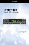
Aviation
0.1
AFM-SUPPLEMENT
AVE 22
AIRPLANE FLIGHT MANUAL
AQUILA AT01
LIST OF REVISIONS AND AMENDMENTS
Revision
Reason for Amendment/Revision
Affected
Pages
Date of
Issue
A.01
Initial Issue (minor change MB-AT01-00297)
all
2009 19.
March
0.2
LIST OF EFFECTIVE PAGES
Page
Revision
Date
AVE22-1 to
AVE20-9
A.01
19.03.2009
0.3
Page
Revision
Date
TABLE OF CONTENTS
Section 1
GENERAL
AVE22 - 3
Section 2
OPERATING LIMITATIONS
AVE22 - 3
Section 3
EMERGENCY PROCEDURES
AVE22 - 3
Section 4
NORMAL PROCEDURES
AVE22 - 4
Section 5
PERFORMANCE
AVE22 - 4
Section 6
WEIGHT AND BALANCE
AVE22 - 4
Section 7
SYSTEMS DESCRIPTION
AVE22 - 5
Section 8
HANDLING, SERVICE AND MAINTENANCE
AVE22 - 9
Document No.:
Issue:
Supersedes Issue:
Date:
Page:
FM-AT01-1010-322
A.01
--.--.----
19.03.2009
AVE22-2
Aviation
AIRPLANE FLIGHT MANUAL
AQUILA AT01
AFM-SUPPLEMENT
AVE 22
1. GENERAL
This Supplement provides the information necessary for the efficient operation of the
AQUILA AT01 when the Mode S Transponder GARRECHT VT-02 is installed. It
contains a general description of the Transponder, its basic operation and its integration
into the AQUILA AT01. For a detailed description of the Mode S Transponder
GARRECHT VT-02 and full operating instructions, refer to the effective issue of the
VT-02 User Manual , 02.0200.10E.
The information contained within this Supplement is to be used in conjunction with the
complete Airplane Flight Manual. Furthermore, the VT-02-User Manual should always
be carried on board of the aircraft during flight.
2. OPERATING LIMITATIONS
A connection of the VT-02 with a TCAS collision avoidance system is currently not
intended for the AQUILA AT01. The operating limitations of the basic Airplane Flight
Manual apply without any changes or restrictions.
3. EMERGENCY PROCEDURES
3.13.3
TO TRANSMIT A SIGNAL REPRESENTING LOSS OF ALL
COMMUNICATION (IN CONTROLLED AIRSPACE):
•
•
•
3.15.2
“Mode” Key:
Double shaft rotary encoder
outer knob
Inner knob of the double
shaft rotary encoder
Press until Mode “ALT” active.
Select 7600 operating code.
Push, activate 7600 operating code.
TO TRANSMIT AN EMERGENCY SIGNAL:
•
•
•
“Mode” Key:
Double shaft rotary encoder
outer knob
Inner knob of the double
shaft rotary encoder
Press until Mode “ALT” active.
Select 7700 operating code.
Activate 7700 operating code.
Document No.:
Issue:
Supersedes Issue:
Date:
Page:
FM-AT01-1010-322
A.01
--.--.----
19.03.2009
AVE22-3
AIRPLANE FLIGHT MANUAL
AQUILA AT01
Aviation
AFM-SUPPLEMENT
AVE 22
4. NORMAL PROCEDURES
NOTE
The expected coverage of the VT-02 is limited to the „line of sight“. Low altitude or
aircraft antenna shielding by the aircraft itself may result in reduced range. Range can
be improved by climbing to a higher altitude.
4.5.3 BEFORE TAXIING
1.
Avionic Master Switch
ON
The transponder will switch into the standby (SBY) mode.
The transponder is activated but will not respond to any interrogations from the
ATC Secondary Surveillance Radar.
4.5.5 BEFORE TAKE-OFF
1.
Transponder Mode Selection Key
ALT
In this mode the transponder will respond in Mode A, Mode C and Mode S
operation (identification and altitude) to interrogations from ATC and TCAS
equipped aircrafts.
NOTE
Pressing the Mode Selection Key “ON” activates only Mode A-operation of the
Transponder. The Transponder will respond to interrogations with the identification code
only. The replies do not include altitude information.
4.5.12 AFTER LANDING
1.
Transponder Mode Selection Key
SBY
5. PERFORMANCE
No change to the basic Airplane Flight Manual.
6. WEIGHT AND BALANCE
The change of the empty weight and corresponding centre of gravity after the
installation or removal of the Garrecht VT-02 Mode S Transponder has to be
Document No.:
Issue:
Supersedes Issue:
Date:
Page:
FM-AT01-1010-322
A.01
--.--.----
19.03.2009
AVE22-4
Aviation
AIRPLANE FLIGHT MANUAL
AQUILA AT01
AFM-SUPPLEMENT
AVE 22
determined and recorded in accordance with section 6 of the basic Airplane Flight
Manual.
7. SYSTEMS DESCRIPTION
GENERAL
The Garrecht VT-02 panel mounted Non-Diversity Mode S Transponder is a radio
transmitter and receiver that operates on radar frequencies, receiving ground radar or
TCAS interrogations at 1030 MHz and transmitting a coded response of pulses to
ground-based radar on a frequency of 1090 MHz. The VT-02 is equipped with IDENT
capability that activates the Special Position Identification (SPI) pulse for 18 seconds.
Mode S transmit/receive capability also requires 1090 MHz transmitting and 1030 MHz
receiving for Mode S functions.
In addition to displaying the selected transponder code, reply symbol and mode of
operation, the VT-02 screen also displays pressure altitude.
The VT-02 transponder is powered on by pressing the “I/O” key. After power on, a startup page will be displayed while the unit performs a self-test. To activate the
Transponder, the ALT/BAT-Master Switch as well as the Avionics Master Switch has to
be in the ON position.
GARRECHT VT-02 FRONT VIEW
TRANSPONDER MODE SELECTION KEYS
Display:
SBY
Selects the standby mode. When in standby mode, the transponder will not
reply to any interrogations.
Document No.:
Issue:
Supersedes Issue:
Date:
Page:
FM-AT01-1010-322
A.01
--.--.----
19.03.2009
AVE22-5
Aviation
AIRPLANE FLIGHT MANUAL
AQUILA AT01
AFM-SUPPLEMENT
AVE 22
ON
Selects MODE A operation of the transponder. In this mode, the transponder
replies to interrogations, as indicated by the Reply Symbol (‘R’). Replies do not
include altitude information.
ALT
Selects MODE A, MODE C and MODE S operation of the transponder. In ALT
mode, the transponder replies to identification and altitude interrogations, as
indicated by the Reply Symbol (‘R’). Replies to altitude interrogations include
the standard pressure altitude received from the internal altitude source
(Altitude Encoder), which is not adjusted for barometric pressure.
Any time the function ON or ALT is selected, the transponder becomes an active part of
the Air Traffic Control Radar Beacon System (ATCRBS). The transponder also
responds to interrogations from TCAS equipped airplanes.
CODE SELECTION
Code selection is done with the double shaft rotary encoder providing 4096 active
identification codes.
Rotating the outer knob of the double shaft encoder selects the position of the code to
be modified. A blinking cursor is indicating the selected position. Use the inner knob to
modify the value at the selected position. When all changes are done, press the inner
button to activate the modified standby code.
NOTE
The identification code should be entered carefully, irrespective if assigned by
ATC, or using a standard transponder code.
Important Codes:
1200 - VFR code for any altitude in the US (Refer to ICAO standards)
2000 - VFR code commonly used in Europe (Refer to ICAO standards)
7000 - VFR code commonly used in Europe (Refer to ICAO standards)
7600 - Loss of communications
7700 - Emergency
Document No.:
Issue:
Supersedes Issue:
Date:
Page:
FM-AT01-1010-322
A.01
--.--.----
19.03.2009
AVE22-6
Aviation
AIRPLANE FLIGHT MANUAL
AQUILA AT01
AFM-SUPPLEMENT
AVE 22
KEYS FOR OTHER VT-02 FUNCTIONS
I/O
To switch on the system, press key “I/O” shortly. After the start, the
unit performs the built in test and shows the operating mode. For
switching off, press key “I/O” for at least 3 seconds. Release the key,
when the LCD becomes blank.
IDENT
IDENT key pressed activates the Special Position Identification (SPI)
Pulse for 18 seconds, identifying your transponder return from others
on the air traffic controller’s screen. The word ‘IDENT’ will appear in the
upper left corner of the display while the IDENT mode is active.
FID
Pressing the flight ID key invokes the menu to setup the flight ID. The
Flight ID is transmitted with every Mode-S interrogation.
NOTE
The flight id may be changed if required. Usually the FID is the callsign
of your aircraft unless field 7 of the flight plan contains other data.
Before each flight check always your flight-id has been set correctly.
VFRFunction
To simplify operation, the VT-02 provides a pre-programmable VFR
code, which can be invoked by pressing the inner knob of the rotary
encoder longer than 2sec.
The previous active reply code will then be moved to the bottom line
(inactive area) and overwrites the existing active value there.
If the pre-programmed reply code is identical with the reply code in the
bottom line, active and standby reply code will just be interchanged.
FUNCTION DISPLAY
In the upper left corner of the LCD screen the current pressure altitude (related to
1013,25 hPa) will be shown as Flight Level (FL).
Replies are indicated by a blinking “R” in the lower left corner of the LCD screen. The
current mode is shown in the centre of the bottom line of the screen. The current
Transponder identification (Squawk) is indicated in the upper right corner of the LCD
screen. The standby Transponder identification is indicated below. The activated mode
will be shown centered in the lower row.
Document No.:
Issue:
Supersedes Issue:
Date:
Page:
FM-AT01-1010-322
A.01
--.--.----
19.03.2009
AVE22-7
Aviation
AIRPLANE FLIGHT MANUAL
AQUILA AT01
AFM-SUPPLEMENT
AVE 22
FAILURE ANNUNCIATION
In case of failure, the system shows a “W” on the LCD screen. Additionally, a frequently
repeated audio signal occurs. Both can be terminated by pressing the “I/O” key shortly.
In case of detecting a fatal failure, the system will be switched into Standby (SBY)
mode. All system operating will be terminated to prevent damages to system
components. In this case, the system screen will show ”FAIL” instead of active and
standby reply code. No transponder data will be transfered.
VT-02 MODE S TRANSPONDER FEATURES
MODE S DATA TRANSMISSION
In addition to 4096 codes and pressure altitude, the VT-02 is capable of transmitting
airplane registration number or flight ID, transponder capability and maximum speed
range.
INTEGRATION INTO THE AQUILA AT01
The electrical circuits of the Mode S Transponder Garrecht VT-02 are connected to the
Avionic Bus of the on-board electrical power supply and protected by a 3 A circuit
breaker which enables the complete disconnection of the Transponder unit from electric
power. The circuit breaker is labelled with a placard denoted “Transponder” and is
installed in the right section of the instrument panel among the other circuit breakers.
Besides of the transponder unit, which is installed in the avionic rack in the midsection
of the instrument panel, a transponder antenna and “Altitude Encoder” is part of the
Transponder system.
The “Altitude Encoder” is connected to the on-board Static Pressure System and is
integrated in the VT-02-transponder. The transponder antenna is installed on the lower
surface of the cockpit structure below the co-pilot’s seat.
For a detailed description of the integration of the Transponder unit into the aircraft and
its connection to the on-board electrical system as well as its installation into the
AQUILA AT01, refer to the effective revision of the Maintenance Manual of the AQUILA
AT01, document no. MM-AT01-1020-100.
Document No.:
Issue:
Supersedes Issue:
Date:
Page:
FM-AT01-1010-322
A.01
--.--.----
19.03.2009
AVE22-8
Aviation
AIRPLANE FLIGHT MANUAL
AQUILA AT01
AFM-SUPPLEMENT
AVE 22
8. HANDLING, SERVICE AND MAINTENANCE
In order to increase the service life of the VT-02 Mode S Transponder, it should always
be deactivated during engine start-up and shut-down since electrical surges during the
start-up may cause damage to the unit.
Document No.:
Issue:
Supersedes Issue:
Date:
Page:
FM-AT01-1010-322
A.01
--.--.----
19.03.2009
AVE22-9