1
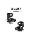
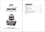
Magnum 1500
user manual
DIMENSIONS
All dimensions are in millimeters
Ø13
305
290
170
145
445
©2005-2007 Martin Professional A/S, Denmark. All rights reserved. No part of this manual
may be reproduced, in any form or by any means, without permission in writing from Martin
Professional A/S. Information subject to change without notice. Martin Professional A/S and
all affiliated companies disclaim liability for any injury, damage, direct or indirect loss, consequential or economic loss or any other loss occasioned by the use of, inability to use or reliance on the information contained in this manual.
P/N 35000160, Rev. D
C ONTENTS
Introduction . . . . . . . . . . . . . . . . . . . . . . . . . . . . . . . . . . . . . . . . . . . 5
Features . . . . . . . . . . . . . . . . . . . . . . . . . . . . . . . . . . . . . . . . . . . . 5
Magnum 1500 overview . . . . . . . . . . . . . . . . . . . . . . . . . . . . . . . . 6
Safety information . . . . . . . . . . . . . . . . . . . . . . . . . . . . . . . . . . . . 7
Unpacking . . . . . . . . . . . . . . . . . . . . . . . . . . . . . . . . . . . . . . . . . . 9
Installation . . . . . . . . . . . . . . . . . . . . . . . . . . . . . . . . . . . . . . . . . . . 10
Physical installation . . . . . . . . . . . . . . . . . . . . . . . . . . . . . . . . . . 10
AC power . . . . . . . . . . . . . . . . . . . . . . . . . . . . . . . . . . . . . . . . . . 13
Installing control hardware . . . . . . . . . . . . . . . . . . . . . . . . . . . . . 14
Operation . . . . . . . . . . . . . . . . . . . . . . . . . . . . . . . . . . . . . . . . . . . . 16
Checking fluid level . . . . . . . . . . . . . . . . . . . . . . . . . . . . . . . . . . 17
Filling the fluid bottle . . . . . . . . . . . . . . . . . . . . . . . . . . . . . . . . . 17
Priming the pump . . . . . . . . . . . . . . . . . . . . . . . . . . . . . . . . . . . . 18
Remote control operation . . . . . . . . . . . . . . . . . . . . . . . . . . . . . . 19
Resetting the thermal cutout . . . . . . . . . . . . . . . . . . . . . . . . . . . 19
Service and maintenance . . . . . . . . . . . . . . . . . . . . . . . . . . . . . . . 21
Replacing the main fuse . . . . . . . . . . . . . . . . . . . . . . . . . . . . . . 21
Uploading new software . . . . . . . . . . . . . . . . . . . . . . . . . . . . . . . 23
Troubleshooting . . . . . . . . . . . . . . . . . . . . . . . . . . . . . . . . . . . . . . 24
Service codes . . . . . . . . . . . . . . . . . . . . . . . . . . . . . . . . . . . . . . . . 25
Optional ducting adapter . . . . . . . . . . . . . . . . . . . . . . . . . . . . . . . 26
Installing a ducting adapter . . . . . . . . . . . . . . . . . . . . . . . . . . . . 26
Magnum 1500 DMX interface module . . . . . . . . . . . . . . . . . . . . . 27
DMX installation . . . . . . . . . . . . . . . . . . . . . . . . . . . . . . . . . . . . . 27
DMX controller operation . . . . . . . . . . . . . . . . . . . . . . . . . . . . . . 33
Magnum 1500 specifications . . . . . . . . . . . . . . . . . . . . . . . . . . . . 34
Disposing of this product
Martin® products are supplied in compliance with Directive 2002/96/EC
of the European Parliament and of the Council of the European Union
on WEEE (Waste Electrical and Electronic Equipment), as amended by
Directive 2003/108/EC, where applicable.
Help preserve the environment! Ensure that this product is recycled at
the end of its life. Your supplier can give details of local arrangements
for the disposal of Martin products.
I NTRODUCTION
Thank you for selecting the Magnum 1500.
The Magnum 1500 is a compact and efficient fog generator for semiprofessional use. It uses a water-based fluid with an aluminum and
copper heat exchanger to create a white fog for entertainment and
theatrical use. The Magnum 1500 can be controlled using the remote
control unit supplied with the product. It can also be controlled via DMX by
adding a module available as a separate accessory.
The most recent version of this manual is available in the Support area of
the Martin website at: http://www.martin.com
Features
• Onboard 2.3 liter (0.6 US gal. / 0.5 imperial gal.) fluid container.
• Remote control with instant fog output or timer-controlled output with
variable run times and fog volume.
• Multiple remote control linking (allows up to 4 Magnum 1500s to be
controlled via one remote control unit).
• DMX control (independent or grouped multiple control on DMX link) with
optional DMX interface.
• 5 meter (16.4 ft.) remote cable.
• Copper and aluminum heat exchanger.
• High pressure pump.
• Efficient insulation.
• Fail-safe thermal cut-out protection.
Introduction
5
Magnum 1500 overview
2
1
10
9
8
7
6
5
3
4
Timer
5
4
6
3
7
1
9
2
12
10
Off
Timer
Fog
11
8
Ready
Heat
4
5
6
7
3
13
2
8
1
9
0
10
Level
6
14
OVERVIEW
1. Safety attachment eye-bolt
2. Mounting bracket
3. Main on/off switch
4. AC power input (EU model illustrated)
5. Fluid bottle release thumbscrews
6. Remote control out
7. Service port
8. Remote control in
9. Fog fluid level check window
10. Fog fluid bottle
11. Timer dial
12. Status indicator LEDs
13. Fog output level dial
14. Instant fog button
Magnum 1500 user manual
Safety information
Warning!
This product is not for household use. It presents risks of
lethal or severe injury due to electric shock, burns, falls and
breathing problems.
Read this manual before powering or installing the machine, follow the
safety precautions listed below and observe all warnings in this manual
and printed on the machine. If you have questions about how to operate
the machine safely, please contact a Martin distributor for assistance or
call the Martin 24-hour service hotline on +45 70 200 201.
Refer any service operation not described in this manual to a qualified
technician.
Preventing electric shocks
• Always ground (earth) the machine electrically.
• Use only a source of AC power that complies with local building and
electrical codes, and that has both overload and ground-fault (earthfault) protection.
• Check the voltage is correct for use with the machine. The voltage
setting is printed on the machine’s serial label.
• Disconnect the machine from AC power before refilling the fluid tank,
resetting the thermal protection cutout, removing covers or servicing.
• Disconnect the machine from AC power when not in use.
• Do not expose this machine to wet outdoor conditions – the machine is
not waterproof.
• Do not spill fluid over the machine. If fluid is spilled, disconnect the
machine from AC power and clean with a damp cloth. If fluid is spilled
onto electronic parts, contact an approved Martin dealer for advice.
• Do not remove the covers or attempt to repair a faulty machine.
• Refer all service to an authorized Martin service dealer.
• Do not operate the machine if the power supply cord is damaged. A
damaged power supply cord must be replaced with a new item,
available from your Martin dealer.
• Do not operate the machine with damaged or missing parts.
• Moisture and electricity do not mix. Do not aim fog output at electrical
connections or devices.
Introduction
7
Preventing burns and fire
• Allow the machine to cool for at least 20 minutes before handling or
opening – the machine becomes hot during use.
• Use only genuine Martin or JEM fluid in the machine.
• Never attempt to bypass the thermostatic switch or fuses. Always
replace defective fuses with ones of the specified type and rating.
• Ensure that the air flow around the machine is free and unobstructed.
• Provide a minimum clearance of 0.1 meters (4 inches) around the
machine.
• Do not touch the output nozzle during or after use; it may stay hot for
several hours.
• Do not operate the machine if the ambient temperature (Ta) exceeds 40°
C (104° F).
• Keep the nozzle at least 0.6 meters (24 inches) away from people and
objects.
• Do not install the machine with the nozzle pointing more than 30° up or
down from horizontal.
Preventing in juries d ue to falls
• Work from a stable platform and block access below the work area
whenever installing, servicing or removing the machine.
• Do not hang the machine directly over people’s heads.
• When suspending the machine above ground level, verify that the
structure can hold at least 10 times the weight of all installed devices.
• Verify that all external covers and rigging hardware are securely
fastened and use an approved means of secondary attachment such as
a safety cable.
• Fog and smoke machines can cause condensation. Do not point the
output at high traffic areas with smooth floors. Floors and surfaces may
become slippery. Check these frequently and wipe dry as necessary to
avoid any danger of slipping.
Preventing breat hing problems
• Always use fog and smoke machines in well-ventilated areas.
Excessive use could affect sufferers of asthma or other respiratory
conditions.
• Never point the output directly at a person’s face or at face height.
8
Magnum 1500 user manual
Unpacking
The packing material is carefully designed to protect the machine during
shipment - always use it to transport the machine.
The Magnum 1500 is supplied with:
• Remote control unit with 5 meter (16.5 ft) cable (RJ45 connector)
• Power cable
• User manual
The Magnum 1500 is supplied with the fluid bottle empty to avoid spillage
during shipment. The fluid bottle must be filled before using for the first
time (see “Filling the fluid bottle” on page 17).
Your Martin/JEM dealer can supply suitable fluid. Use only one of the
following fluid types:
• JEM/Martin Pro Smoke Super
• JEM/Martin Regular DJ (DJ mix)
Warning!
Using any other type of fluid can cause a health hazard and
cause damage to the machine that is not covered by the
product warranty.
Introduction
9
I NSTALLATION
Physical installation
The Magnum 1500 may be either suspended from a suitable support by
means of its adjustable mounting bracket or placed on a flat level surface.
Do not install the machine by any other means, as this can cause
overheating or malfunction.
Warning!
To allow adequate cooling, the Magnum 1500 must be located
at least 0.1 meters (4 in.) from any surface.
The Magnum 1500 must be located well away from flammable
materials.
The Magnum 1500’s surface temperature can reach 50°C (122°
F) and the nozzle can reach 200°C (392° F). The machine must
be positioned well out of reach of the public in a location
where accidental contact is impossible.
Do not install the Magnum 1500 at an angle of more than 30°
up or down from horizontal.
To avoid fluid leakage, the fluid bottle filler cap must always point upwards.
If necessary, the fluid bottle can be repositioned (see “Repositioning the
fluid bottle” on page 12).
Suspending from a support
Warning!
Block access below the work area and work from a stable
platform when installing.
Always use a secure means of secondary attachment that can
hold at least 10 times the weight of the machine.
1. If using a rigging clamp (not included), verify that the clamp is
undamaged and can bear at least 10 times the machine’s weight. Bolt
the clamp securely to the machine’s mounting bracket with a grade 8.8
(minimum) M12 bolt and lock nut, or as recommended by the clamp
10
Magnum 1500 user manual
manufacturer, through the 13 mm hole in the center of the mounting
bracket.
2. If fastening the machine directly to a mounting surface using the
adjustable mounting bracket, verify that all fasteners used and the
mounting surface can bear at least 10 times the machine’s weight. The
mounting bracket may be fastened to a surface using the 13 mm hole
in the mounting bracket.
3. Verify that the structure used to support the machine can support at
least 10 times the total weight of all installed fixtures, clamps, cables,
auxiliary equipment, etc.
4. Install a safety wire that can hold at least 10 times the weight of the
machine through/over the support and through the eye-bolt on the
housing below the mounting bracket (see illustration).
Safety wire attachment
Do not simply attach the safety wire to the mounting bracket, as this
will leave the machine unsecured.
5. Loosen the swivel locks and position the machine at any angle within
30° of horizontal. Turn the swivel locks clockwise to tighten. Check that
the machine is securely clamped in position.
Placing on a hor izontal su rface
If preferred, the Magnum 1500 can be installed on a level horizontal
surface, resting either on its rubber feet or on its mounting bracket. The
mounting bracket can be used to support the machine at an angle. If the
machine is to be placed on a horizontal surface:
• Ensure that the surface is level, stable and capable of supporting at
least ten times the weight of the machine.
• Attach the machine securely so that it cannot slide or fall off the surface.
Installation
11
• Eliminate any risk of accidental contact.
• Do not aim the machine at face height.
• Keep the nozzle at least 60 centimeters (24 inches) away from people
and objects.
Repositioning the fluid bottle
Resting the Magnum 1500 on its mounting bracket means operating it
upside-down. This does not affect operation, but to avoid leaks the fluid
bottle must also be repositioned so that the filler cap remains at the top.
To reposition the fluid bottle:
1. Open the fluid bottle
compartment by twisting
the two thumbscrews a
quarter-turn in towards the
centre of the machine and
pulling the cover off the
machine.
Fluid bottle compartment cover
thumbscrews
2. Slide the fluid bottle out of
the compartment.
3. Turn the Magnum 1500
over so that the mounting
bracket sits underneath it.
Slide the fluid bottle back
into its compartment with
the filler cap pointing
upwards, being careful not
to trap or kink the fluid
hose.
4. Replace the compartment
cover and re-tighten the
thumbscrews.
12
Fluid bottle removal/replacement
Magnum 1500 user manual
AC power
The Magnum 1500 is available in two models:
• US model (120 V, 60Hz for 105-115 VAC power supplies)
• EU model (230 V, 50Hz for 220-245 VAC power supplies)
The Magnum 1500 is supplied set up to match local voltage and
frequency settings. The factory default setting is shown on the serial
number label.
Warning!
For protection from fire and electric shock, the Magnum 1500
must be grounded (earthed). The power supply must have
overload and ground-fault (earth-fault) protection.
Check that power cables are undamaged and rated for the
current requirements of all connected devices before use.
Check the power supply setting before applying power.
Installing a plug on t he power cable
The power cable must be fitted with a grounding-type cord cap (earthedtype mains plug) that fits your power distribution system. Consult a
qualified electrician if you have any doubts about proper installation.
Following the cord cap manufacturer’s instructions, connect the yellow
and green wire to ground (earth), the brown wire to live, and the blue wire
to neutral. The table below shows some pin identification schemes:
Wire
Pin
Marking
Screw color
brown
live
“L”
yellow or brass
blue
neutral
“N”
silver
yellow/green
ground
green
Table 1: Cord cap wiring
Installation
13
Installing control hardware
The Magnum 1500 can be operated using:
• the remote control unit supplied with the machine, or
• a DMX controller using an interface that is available as an accessory
from your Martin dealer (P/N 91612000). Installing DMX control
hardware is covered in “DMX installation” on page 27 of this manual.
Remote control unit installation
To install the remote control unit:
1. Power the machine off.
2. Plug the RJ-45 connector on the remote control cable into the IN socket
on the connections plate (see illustration).
Remote control IN
Remote Control
Out
In
Remote control OUT
3. When you power the machine on again, check that the HEAT indicator
on the remote control is lit to show that the machine is warming up.
Multiple linking with a remote control unit
The Magnum 1500’s multiple linking feature allows more than one
machine to be controlled using the remote control. If machines are linked,
all machines receive the same instructions from the remote control and
behave identically. Up to four Magnum 1500s can be linked to the remote
control.
For multiple link operation, machines must be linked using shielded data
cable with at least one twisted pair that is designed for RS-485
14
Magnum 1500 user manual
applications. The cable must be fitted with RJ-45 connectors. Your Martin
dealer can supply suitable high-quality cable in various lengths.
Important! Make sure multiple link cables are connected in a daisy-chain,
output to input: if an output is linked to an output, damage
can occur which is not covered by the product warranty.
To link Magnum 1500s:
1. Power off all machines.
2. Connect the remote control unit to the IN socket on the first Magnum
1500 on the link.
3. Lead a suitable cable from the OUT socket on the first Magnum 1500
to IN on the next Magnum 1500. If more machines are to be operated
together, continue linking them, connecting output to input. Up to 4
machines can be connected to one remote control in this way.
4. Apply power to the machines and allow them to warm up. All machines
will now respond to commands sent from the remote control.
Installation
15
O PERATION
The Magnum 1500 can be operated using the remote control unit supplied
with the machine or by means of a DMX controller using a DMX interface
module (P/N 91612000) that is available separately as an accessory from
your Martin dealer. Extra information about DMX operation is covered in
“DMX controller operation” on page 33 of this manual.
Before powering on, check that:
• The Magnum 1500 is correctly and safely installed.
• The fluid bottle is full (see “Filling the fluid bottle” on page 17).
• The pump has been primed if the machine is new or has not been used
for some time (see “Priming the pump” on page 18).
For the Magnum 1500 to work, the remote control must be connected, or
the machine must be linked to an active control device (a DMX controller
or another Magnum 1500 on a multiple link).
Power on at the Magnum 1500 on/off switch. The HEAT indicator LED on
the remote control will light and the LED on the machine close to the
remote control sockets will light red to indicate pre-heating. The machine
should be ready for operation in less than eight minutes.
When the Magnum 1500 reaches operating temperature, the READY
indicator LED on the remote control will light and the LED on the Magnum
1500 close to the remote control sockets will change from red to orange.
The machine is now ready for use.
The LED on the Magnum 1500 may change between orange and green
periodically. This is normal. Orange indicates that the heating element is
active, green indicates that the heating element is inactive. The HEAT
indicator LED on the remote control will also light when the heating
element is active. The LED lights red when output is interrupted during
pre-heating.
Heating element activity is reduced to almost zero if the Magnum 1500
runs low on fluid. If the LEDs show that the heating element is almost
never active, power the machine off and check the fluid level.
16
Magnum 1500 user manual
Checking fluid level
Important! Check the fluid level regularly. Running the machine without
fluid will eventually cause damage to the pump which is not
covered by the product warranty.
Check fluid level regularly. If the machine is horizontal, the level in the
fluid bottle can be checked via the window on the fluid bottle compartment
cover. If the machine is at an angle, the cover must be opened and the
bottle removed to check the fluid level.
Filling the fluid bottle
Warning!
Always disconnect the machine from power before working
with the fluid system. The fluid bottle must be removed from
the machine for filling.
Use only Martin or JEM fog fluid of the following types:
• Regular DJ Fluid (DJ mix)
• Pro Smoke Fluid (ZR mix)
To fill the fluid bottle:
1. Disconnect the machine
from the power supply.
2. Remove the fluid bottle
compartment cover by
twisting the two
thumbscrews a quarterturn in towards the centre
of the machine and pulling
the cover off the machine.
Operation
17
3. Slide the fluid bottle out of
the compartment and
remove the cap with
attached fluid suction hose
from the bottle.
4. Fill the bottle with Martin or
JEM Pro Smoke Fluid (ZR
mix) or Regular DJ Fluid
(DJ mix) only.
5. Check that the filter on the
end of the fluid suction
hose is clean and replace
the cap tightly, ensuring
that the hose reaches the
bottom of the bottle.
6. Slide the fluid bottle back into its compartment, being careful not to trap
or kink the fluid hose.
7. Replace the compartment cover before reapplying power.
Priming the pump
The pump must be primed when the Magnum 1500 is used for the first
time, or if it has not been used for an extended period.
To prime the pump:
1. Check that the fluid bottle is full. Power the machine on and allow it to
reach operating temperature.
2. If using the remote control, set the TIMER on the remote control to
zero, set LEVEL to maximum and press the FOG button for 10 - 15
seconds.
3. If using DMX, set the machine to maximum fog output for 10 - 15
seconds.
18
Magnum 1500 user manual
Remote control operation
The remote control supplied with the Magnum 1500 gives feedback on
the status of the machine. It also allows you to create instant fog or set a
timer to create fog at intervals. Duration and volume of fog production can
be varied during timer operation.
• Use the TIMER knob to set fog
output run times from zero to 10
(maximum).
• Use the LEVEL knob to set the
volume of fog output from zero to
10 (maximum).
Timer
2
• The TIMER indicator lights when
the timer function is active.
Timer
• The HEAT indicator lights when
the heating element is active. It
should light continuously during
pre-heating, light occasionally
during operation and light
continuously during re-heating.
6
3
7
1
9
8
10
Off
Fog
• The READY indicator lights when
the Magnum 1500 is ready to
produce fog.
5
4
• If you set the TIMER knob to 0,
you can produce instant fog by
pressing the FOG button.
Ready
Heat
4
5
6
3
7
1
9
2
8
0
10
Level
Note that the Magnum 1500 is not designed to give continuous output at
the highest levels. If you set the output level to 10 (maximum), output will
be interrupted after approximately 50 seconds while the machine reheats. Re-heating takes less than 2 minutes. The level at which output is
continuous will vary depending on ambient and fluid temperatures, but
output levels up to at least 5 are normally continuous.
Resetting the thermal cutout
The Magnum 1500 is fitted with a thermal cutout to protect against
overheating. If for any reason the heating element temperature exceeds
normal operating level, the thermal cutout shuts down the power.
Operation
19
If this occurs, you will need to manually reset the thermal cutout. To do
this:
1. Isolate the machine from power by disconnecting the power cable and
allow the machine to cool for at least 20 minutes.
2. If the machine is resting on its rubber feet, remove the fluid
compartment cover, remove the fluid bottle and turn the machine over
so that it is resting on its mounting bracket.
3. Remove the four T20 Torx screws in the rubber feet and slide the
baseplate away from the nozzle end of the machine to give access to
the reset switch cover.
4. Remove the four T20 Torx screws from the reset switch cover and lift
the cover off the machine..
5. Press the plastic reset switch to reset the thermal protection cutout.
6. Replace all covers and screws before reapplying power.
If the thermal cutout operates repeatedly, contact your Martin dealer for
service.
20
Magnum 1500 user manual
SERVICE AND MAINTENANCE
Any service procedure not described here should be referred to a
qualified technician.
Warning!
Disconnect the machine from the power supply and allow to
cool for at least 20 minutes before handling. Be extremely
careful of the nozzle, which can remain hot for several hours
after the exterior of the machine has cooled.
Replacing the main fuse
The Magnum 1500 uses a time-delay fuse for protection against current
overload. An indication that the fuse may have blown is that the indicator
LEDS do not light if power is applied when the machine is correctly
connected to power and to either the remote control or a valid DMX
signal.
Never bypass the fuse or replace it with one of another size or rating.
To replace the main fuse:
1. Disconnect the machine from AC power and allow to cool.
2. Remove the three T25 Torx screws from the rubber protection molding
around the control interface module, pull off the rubber molding and,
being careful not to strain any wires, gently pull the interface module
away from the housing.
Service and maintenance
21
3. Remove the two outer T25
Torx screws from the rubber
protector molding at the
opposite end of the
machine, as illustrated, to
release the side cover on
that side of the machine.
4. Slide the side cover
completely off the machine to
give access to the control
circuit board.
5. The main fuse is located in a fuseholder on the control circuit board.
Gently pull the circuit board out a few centimeters to give access to the
fuseholder.
22
Magnum 1500 user manual
6. Pull the fuseholder cover off the base and remove the fuse from its clip.
It may improve access if you temporarily disconnect the spade
connector underneath the fuse holder.
7. Replace the fuse with one of the same type. The fuse rating is listed on
the serial number label and in “Magnum 1500 specifications” on page
34 of this manual.
8. Replace the fuseholder cover and any connectors.
9. Reassembly is the reverse of the disassembly procedure. Be careful
not to trap any wires when replacing covers. Do not reapply power until
all covers and screws are in place and secure.
If the fuse blows repeatedly, disconnect the machine from the power
supply and from control equipment and contact your Martin/JEM dealer.
Uploading new software
The Magnum 1500’s software can be reloaded or upgraded via the
service port. The heater must be re-calibrated if new software is installed.
Pump output can only be calibrated via software updates. Martin/JEM
service agents can carry out software updates for you.
Service and maintenance
23
TROUBLESHOOTING
Problem
Probable cause(s)
Suggested remedy
Heater not at operating
temperature
Allow time to warm up,
wait for READY LED on
remote control to light or
LED on machine to light
orange or green
Fluid below minimum
level
Refill
Airlock in pump
Prime pump
No power
Check power supply,
on/off switch and
connections
Control device not
connected
Check connections
Fog disperses too
quickly
Wrong grade of fluid
used for the application
Consult your Martin
dealer
Fuse blows repeatedly
Electrical malfunction
Refer to service
technician
Incorrect DMX address
Check DIP-switch
settings
Machine not ready
Allow time to warm up,
wait for LED on machine
to change from red to
orange or green
No DMX termination
Fit termination plug to
last device on DMX link
Airlock in pump
Prime pump
LEDs light, but no fog
output when machine is
fired using Fog or Timer
switch
No light from LEDs on
remote control or
connections module
LED on machine lights,
but no fog output when
machine is fired using
DMX
24
Magnum 1500 user manual
SERVICE CODES
If an error occurs during operation, the READY indicator LED on the
remote control and the LED above the service port close to the remote
control sockets both flash service codes that can be useful
troubleshooting aids.
Timer
5
4
6
7
3
2
8
1
9
10
Off
Fog
Timer
Ready
Heat
4
5
6
7
3
2
8
1
9
0
10
Level
If the Magnum 1500 flashes a service code, reset the machine by
powering off and on again. If the code persists, refer to your Martin dealer.
Service code
Message
One short blink every second
(approx.)
Overheating error or calibration
error
LEDs flash constantly
Calibration mode
Two short blinks every second
(approx.)
Calibration completed
Service codes
25
O PTIONAL DUCTING ADAPTER
Fog/smoke ducting gives flexibility in directing fog output. It can also allow
you to install the Magnum 1500 in a safe location with convenient access
for refilling, service, etc.
The Magnum 1500 can be connected to standard 4-inch (102 mm)
fog/smoke ducting using an adapter. Your Martin dealer can supply this
adapter as an accessory pack (P/N 92625008) that also contains 5 m
(16.4 ft.) of ducting.
Installing a ducting adapter
Warning!
Airflow is necessary at the entrance to the ducting. Never
block the air gap between the Magnum 1500 and the ducting
adapter.
To install the optional ducting adapter:
1. Working at the nozzle end of the machine, remove the two T20 Torx
screws that hold the rubber feet in place on the bottom of the machine,
and remove the two screws in the same place on the top of the
machine.
2. Place the ducting adapter over the nozzle so that the adapter mounting
holes line up with the holes in the housing, and replace the screws and
rubber feet.
26
Magnum 1500 user manual
MAGNUM 1500 DMX INTERFACE MODULE
The Magnum 1500 can be controlled using a DMX controller on a serial
data link if a DMX interface module is installed. This module is available
separately as an optional accessory (DMX Interface Module, Magnum
1500, P/N 91612000).
Up to 32 devices can be controlled via DMX on one serial data link. The
link must be daisy-chained in one single line, maximum 500 meters (1640
ft.) long. More devices can be added and the link can be extended beyond
500 meters or branched using an optically isolated splitter/amplifier such
as the Martin RS-485 Opto-Splitter (P/N 90758060).
DMX installation
To use a DMX controller with the Magnum 1500, you must remove the
remote control module that is fitted as standard and fit a DMX module in
its place.
Installing a DMX module
To install a DMX control module:
1. Disconnect the power supply cable and allow the machine to cool for at
least 20 minutes.
2. Remove the three T25 Torx screws on the remote control connections
module and remove the black rubber protection molding.
Magnum 1500 DMX interface module
27
3. Being careful to avoid straining any wires, pull the module gently
outwards and to one side. Note the position of the module’s wiring
connector, with the wires facing away from the locking tab on the circuit
board connector, and disconnect it from the 6-pin plug on the circuit
board inside the housing. Then remove the module completely.
Remove 6-pin remote
control connector
Insert 3-pin DMX
interface connector
Locking tab
4. The DMX interface module has a 3-pin female wiring connector. This
must be connected to the 3-pin male connector on the circuit board –
not the 6-pin connector used by the remote control module (see
illustration).
5. Hold the DMX module up to the housing and push the DMX interface
connector in so that its wires face away from the locking tab on the
circuit board connector. The locking ridge molded into the end of the
DMX interface connector must face towards the locking tab on the
circuit board connector. The wiring connector is an easy sliding fit. If
you need to force it, you may be trying to insert it the wrong way round.
28
Magnum 1500 user manual
6. Line up the edge of the
circuit board on the DMX
adapter module so that it
can slide into the groove in
the screw hole in the
housing and gently push
the DMX adapter into
place, being careful not to
trap any wires.
7. Replace the black rubber
molding and the three Torx
screws.
DMX cable connection
A reliable data link requires suitable cable. Standard microphone cable
cannot transmit DMX data reliably over long runs. For best results, use
shielded cable with at least one twisted pair specifically designed for RS485 applications. Your Martin dealer can supply suitable high quality cable
in various lengths.
The Magnum 1500’s XLR data sockets are wired with pin 1 to ground, pin
2 to signal - (cold), and pin 3 to signal + (hot). This is the standard pin
assignment for DMX devices.
One or more adaptor cables may be required to connect the Magnum
1500 to the controller and/or other types of fixture, because some devices
may have 5-pin XLR connectors and others may have reversed signal
polarity (pin 2 hot and pin 3 cold). The required connector polarity is
normally labelled on devices and specified in user manuals.
5-pin to 3-pin
Adaptor
3-pin to 5-pin
Adaptor
Male
Female
Male
Female
Male
Female
1
2
3
4
5
1
2
3
1
2
3
1
2
3
4
5
1
2
3
1
2
3
P/N 11820005
3-pin to 3-pin
Phase-Reversing
Adaptor
P/N 11820004
P/N 11820006
DMX connection pins and polarity
Magnum 1500 DMX interface module
29
To connect a 5-pin XLR output to the Magnum 1500, use a 5-pin male to
3-pin female XLR adaptor cable (P/N 11820005). To connect the Magnum
1500 to a 5-pin XLR input, use a 3-pin male to 5-pin female adaptor cable
(P/N 1820004). To connect to devices with reversed polarity, use a phasereversing adaptor (P/N 1820006)
To connect a DMX data link:
1. Power off all devices.
2. Using suitable data cable, connect the controller’s DMX output to the
first device’s DMX input.
3. Connect the DMX output of the first device to the DMX input of the next
device.
4. Continue connecting devices output to input.
5. Terminate the link by inserting a male termination plug (available from
your Martin dealer: P/N 91613017) into the DMX output of the last
device. A termination plug is simply an XLR connector with a 120 Ohm,
0.25 W resistor soldered across pins 2 and 3.
S p e c ifyin g D MX c o n t rol addresses
The Magnum 1500 uses a single DMX control channel to receive
instructions from the controller. This control channel is the Magnum 1500’s
DMX address. The DMX address must be set on the Magnum 1500 for
instructions to be received successfully on this channel from the controller.
To control devices individually, each must have its own unique DMX
address. To control devices as a group, they can all be given the same
DMX address. They will then receive the same instructions and should
behave identically. Setting up identical devices with the same DMX
address can also be a good tool for troubleshooting unexpected behavior.
A Magnum 1500’s DMX address can be set to any channel from 1 to 511
using DIP-switches 1 - 9 on the DMX module.
To set the DMX address:
1. Choose an available address for the Magnum 1500.
2. Look up the DIP-switch settings for this address using the Martin
Address Calculator at
http://www.martin.dk/service/utilities/AddrCalc/index.asp or look for the
address in the DIP-switch settings table on page 32. For example, to
30
Magnum 1500 user manual
set the DMX address to 101, you need to set DIP-switch pins 1, 3, 6
and 7 to ON, as shown in the illustration below:
3. Power off the controller and all the machines you want to connect to
the DMX link.
4. For each machine, set the DMX address by setting the DIP-switch pins
1 through 9 to the ON (1) or OFF (0) position as listed in the table on
the next page. As an example, channel 101 is highlighted in the table.
Magnum 1500 DMX interface module
31
DMX address DIP- switch settings
Find the DMX address you want to set in the following table. Read the
settings for pins 1 - 5 to the left and read the settings for pins 6 - 9 above
the address. “0” means OFF and “1” means ON. Pin 10 is always OFF for
DMX operation.
For example, to set a DMX address to 101, set pins 1, 3, 6 and 7 to ON,
and the other pins to OFF.
DIP-Switch Setting
#1
0
1
0
1
0
1
0
1
0
1
0
1
0
1
0
1
0
1
0
1
0
1
0
1
0
1
0
1
0
1
0
1
32
0 = OFF
1 = ON
#2 #3 #4
0
0
0
0
0
0
1
0
0
1
0
0
0
1
0
0
1
0
1
1
0
1
1
0
0
0
1
0
0
1
1
0
1
1
0
1
0
1
1
0
1
1
1
1
1
1
1
1
0
0
0
0
0
0
1
0
0
1
0
0
0
1
0
0
1
0
1
1
0
1
1
0
0
0
1
0
0
1
1
0
1
1
0
1
0
1
1
0
1
1
1
1
1
1
1
1
#5
0
0
0
0
0
0
0
0
0
0
0
0
0
0
0
0
1
1
1
1
1
1
1
1
1
1
1
1
1
1
1
1
#9
#8
#7
#6
0
0
0
0
0
0
0
1
0
0
1
0
0
0
1
1
0
1
0
0
0
1
0
1
0
1
1
0
0
1
1
1
1
0
0
0
1
0
0
1
1
0
1
0
1
0
1
1
1
1
0
0
1
1
0
1
1
1
1
0
1
1
1
1
1
2
3
4
5
6
7
8
9
10
11
12
13
14
15
16
17
18
19
20
21
22
23
24
25
26
27
28
29
30
31
32
33
34
35
36
37
38
39
40
41
42
43
44
45
46
47
48
49
50
51
52
53
54
55
56
57
58
59
60
61
62
63
64
65
66
67
68
69
70
71
72
73
74
75
76
77
78
79
80
81
82
83
84
85
86
87
88
89
90
91
92
93
94
95
96
97
98
99
100
101
102
103
104
105
106
107
108
109
110
111
112
113
114
115
116
117
118
119
120
121
122
123
124
125
126
127
128
129
130
131
132
133
134
135
136
137
138
139
140
141
142
143
144
145
146
147
148
149
150
151
152
153
154
155
156
157
158
159
160
161
162
163
164
165
166
167
168
169
170
171
172
173
174
175
176
177
178
179
180
181
182
183
184
185
186
187
188
189
190
191
192
193
194
195
196
197
198
199
200
201
202
203
204
205
206
207
208
209
210
211
212
213
214
215
216
217
218
219
220
221
222
223
224
225
226
227
228
229
230
231
232
233
234
235
236
237
238
239
240
241
242
243
244
245
246
247
248
249
250
251
252
253
254
255
256
257
258
259
260
261
262
263
264
265
266
267
268
269
270
271
272
273
274
275
276
277
278
279
280
281
282
283
284
285
286
287
288
289
290
291
292
293
294
295
296
297
298
299
300
301
302
303
304
305
306
307
308
309
310
311
312
313
314
315
316
317
318
319
320
321
322
323
324
325
326
327
328
329
330
331
332
333
334
335
336
337
338
339
340
341
342
343
344
345
346
347
348
349
350
351
352
353
354
355
356
357
358
359
360
361
362
363
364
365
366
367
368
369
370
371
372
373
374
375
376
377
378
379
380
381
382
383
384
385
386
387
388
389
390
391
392
393
394
395
396
397
398
399
400
401
402
403
404
405
406
407
408
409
410
411
412
413
414
415
416
417
418
419
420
421
422
423
424
425
426
427
428
429
430
431
432
433
434
435
436
437
438
439
440
441
442
443
444
445
446
447
448
449
450
451
452
453
454
455
456
457
458
459
460
461
462
463
464
465
466
467
468
469
470
471
472
473
474
475
476
477
478
479
480
481
482
483
484
485
486
487
488
489
490
491
492
493
494
495
496
497
498
499
500
501
502
503
504
505
506
507
508
509
510
511
Magnum 1500 user manual
DMX controller operation
When the Magnum 1500 is powered on, the LED on the DMX module
next to the DIP-switches lights to indicate that a valid DMX signal is being
received, and the machine starts to warm up. The Magnum 1500 is ready
for operation after approximately 10 minutes.
Set the level on the Magnum 1500’s DMX control channel to zero to cut
fog output to zero. Increase the level on the machine’s DMX control
channel to increase the level of fog output.
D MX c o n tr o l c h a n n e l l e v e l s
Level
Percentage
Effect
0-27
28-255
0-10%
11-100%
No fog output
Fog output increases in 24 increments
Magnum 1500 DMX interface module
33
MAGNUM 1500 SPECIFICATIONS
Physical
Size (L x W x H) . . . . . . . . . . . . . . . . . 445 x 204 x 178 mm (17.5 x 8.0 x 7.0 in.)
Height with bracket attached . . . . . . . . . . . . . . . . . . . . . . . . . . . 375 mm (14.8 in.)
Dry weight . . . . . . . . . . . . . . . . . . . . . . . . . . . . . . . . . . . . . . . . . 11.1 kg (24.5 lbs)
Construction
Housing . . . . . . . . . . . . . . . . . . . . . . . . . . . . . . . . . . . . . . . . . . . . .Steel/aluminum
Installation
Minimum clearance in front of output nozzle. . . . . . . . . . . . . . . . . . . 60 cm (2 ft.)
Minimum clearance around machine . . . . . . . . . . . . . . . . . . . . . . . . 0.1 m (4 in.)
Orientation. . . . . . . . . . . . . . . . . . . . . . . . . . . . . . . .Maximum 30° from horizontal
Fluid system
Fluid pump . . . . . . . . . . . . . . . . . . . . . . . . . . . . . Oscillating piston high pressure
On-board fluid capacity . . . . . . . . . . . . . . . 2.3 liters (4.0 Imp. pints/4.9 US pints)
Maximum fluid consumption:
. . . . . . . . . . . . . . . . . . . . . . 80 ml (0.14 Imp. pints/0.17 US pints) per minute
. . . . . . . 64 ml (0.11 Imp. pints/ 0.14 US pints) per max. run time (48 secs).
Thermal
Maximum ambient temperature (Ta) . . . . . . . . . . . . . . . . . . . . . . . . 40°C (104°F)
Exterior surface temperature under steady state condition . . . . . . 50°C (122°F)
Nozzle temperature. . . . . . . . . . . . . . . . . . . . . . . . . . . . . . . . up to 200°C (395°F)
Time required to cool before service . . . . . . . . . . . . . . . . . Minimum 20 minutes
Control and programming
Control options:
. . . . . . . . . . . . . . . . . . . . . . . . . . . . . . . . . . . . Remote control unit (supplied)
. . . . . . . . . . . . . . . . . . . . . . . . . . . DMX with optional DMX interface module
Control protocol . . . . . . . . . . . . . . . . . . . . . . . . . . . . . . . USITT DMX-512 (1990)
DMX channels . . . . . . . . . . . . . . . . . . . . . . . . . . . . . . . . . . . . . . . . . . . . . . . . . . 1
DMX addressing . . . . . . . . . . . . . . . . . . . . . . . . . . . . . . . . . . . . . . . . . DIP-switch
Connections
Remote control (standard) . . . . . . . . . . . . . . . . . . . . . . . . . . . . . . . . . . . . . RJ-45
DMX (option) . . . . . . 3-pin locking XLR, pin 1 shield, pin 2 cold (-), pin 3 hot (+)
PC/uploader . . . . . . . . . . . . . . . . . . . . . . . . . . . . . . . . . . . . . . . . . . . . . serial port
34
Magnum 1500 user manual
Maximum power and current (+/- 5%)
EU model
@ 220 V, 50 Hz . . . . . . . . . . . . . . . . . . . . . . . . . . . . . . . . . . . . . . . 1140 W, 5.3 A
@ 230 V, 50 Hz . . . . . . . . . . . . . . . . . . . . . . . . . . . . . . . . . . . . . . . 1240 W, 5.5 A
@ 240 V, 50 Hz . . . . . . . . . . . . . . . . . . . . . . . . . . . . . . . . . . . . . . . 1350 W, 5.7 A
US model
@ 110 V, 60 Hz . . . . . . . . . . . . . . . . . . . . . . . . . . . . . . . . . . . . . . . . 880 W, 8.0 A
@ 115 V, 60 Hz . . . . . . . . . . . . . . . . . . . . . . . . . . . . . . . . . . . . . . . . 960 W, 8.4 A
@ 120 V, 60 Hz . . . . . . . . . . . . . . . . . . . . . . . . . . . . . . . . . . . . . . . 1040 W, 8.7 A
Fuse
Main fuse (EU model) . . . . . . . . . . . . . . . . . . . . . . . . . . . 6.3 AT (P/N 05020020)
Main fuse (US model) . . . . . . . . . . . . . . . . . . . . . . . . . . . . 10 AT (P/N 05020025)
Included items (EU model)
3 m (9.8 ft) IEC power cable 3x1.0mm2 with Schuko male connector
3 m (9.8 ft) IEC power cable 3x1.0mm2 with no male connector
User manual. . . . . . . . . . . . . . . . . . . . . . . . . . . . . . . . . . . . . . . . . . P/N 35000160
Remote control with 5 m (16.4 ft) cable and RJ-45 connector. . . . P/N 92765028
Included items (US model)
2 m (6.5 ft) US power cable 18AWG with US male connector (UL approved)
User manual. . . . . . . . . . . . . . . . . . . . . . . . . . . . . . . . . . . . . . . . . . P/N 35000160
Remote control with 5 m (16.4 ft) cable and RJ-45 connector. . . . P/N 92765028
Accessories
Magnum 1500 DMX interface module . . . . . . . . . . . . . . . . . . . . . P/N 91612000
JEM/Martin fog fluid, Regular DJ . . . . . . . . . . . . . . . . . . . Various sizes available
JEM/Martin fog fluid, Pro Smoke Super (ZR Mix) . . . . . . Various sizes available
DMX termination plug (end of link), XLR male . . . . . . . . . . . . . . . P/N 91613017
5-pin male to 3-pin female XLR adaptor cable . . . . . . . . . . . . . . . P/N 11820005
Ducting system (includes adapter and
5m (16.4 ft.) of 4 in. (104mm) ducting . . . . . . . . . . . . . . . . . . . P/N 92625008
G-clamp . . . . . . . . . . . . . . . . . . . . . . . . . . . . . . . . . . . . . . . . . . . . P/N 91602003
Half-coupler clamp . . . . . . . . . . . . . . . . . . . . . . . . . . . . . . . . . . . . P/N 91602005
Ordering information
Magnum 1500 (230 V, 50 Hz EU model) . . . . . . . . . . . . . . . . . . . P/N 91120000
Magnum 1500 (110 V, 60 Hz US model) . . . . . . . . . . . . . . . . . . . . P/N 91120100
Martin Professional A/S • Olof Palmes Allé 18 • 8200 Aarhus N • Denmark
Tel: +45 8740 0000 • Internet: www.martin.com