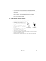
1
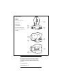
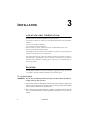
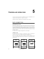
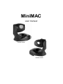
MiniMAC
user manual
MiniMAC Wash
MiniMAC Profile
1
data connection
2
base fan
3
head fan
4
AC input & main fuse
5
cover locks
6
lamp access
7
control panel
8
eye bolt for safety cable
9
Omega clamp attachment
bracket
©1999 - 2000 Martin Professional A/S, Denmark.
All rights reserved. No part of this manual may be
reproduced, in any form or by any means, without
permission in writing from Martin Professional A/S,
Denmark.
Printed in Denmark.
P/N 35000084, Rev. D
INTRODUCTION . . . . . . . . . . . . . . . . . . . . . . . . . . . . . . . . . . . . . . . 4
AC POWER . . . . . . . . . . . . . . . . . . . . . . . . . . . . . . . . . . . . . . . . . . 6
INSTALLATION . . . . . . . . . . . . . . . . . . . . . . . . . . . . . . . . . . . . . . . . 8
CONTROL PANEL . . . . . . . . . . . . . . . . . . . . . . . . . . . . . . . . . . . . . 10
CONTROLLER OPERATION . . . . . . . . . . . . . . . . . . . . . . . . . . . . . . 18
AUTOMATIC STAND-ALONE . . . . . . . . . . . . . . . . . . . . . . . . . . . . . 21
PROGRAMMED STAND-ALONE . . . . . . . . . . . . . . . . . . . . . . . . . . . 24
LAMP . . . . . . . . . . . . . . . . . . . . . . . . . . . . . . . . . . . . . . . . . . . . . 28
GOBOS . . . . . . . . . . . . . . . . . . . . . . . . . . . . . . . . . . . . . . . . . . . . 30
WASH FIELD ANGLE . . . . . . . . . . . . . . . . . . . . . . . . . . . . . . . . . . 32
BASIC SERVICE . . . . . . . . . . . . . . . . . . . . . . . . . . . . . . . . . . . . . . 33
TROUBLESHOOTING. . . . . . . . . . . . . . . . . . . . . . . . . . . . . . . . . . . 37
DMX PROTOCOL . . . . . . . . . . . . . . . . . . . . . . . . . . . . . . . . . . . . . 38
SPECIFICATIONS . . . . . . . . . . . . . . . . . . . . . . . . . . . . . . . . . . . . . 41
3
1
INTRODUCTION
Thank you for selecting the Martin MiniMAC Profile or MiniMAC Wash. Both of
these automated luminaires provide 12 dichroic color filters, high-speed mechanical
shutter, 540° of pan by 270° of tilt, 3-digit LED control panel, DMX, MC-1, standalone, and master/slave control options; and switch-selectable power supply
settings. The MiniMAC Profile provides a 17° hard-focused beam, manually
adjustable focus, and 7 interchangeable rotating gobos. The MiniMAC Wash
provides a soft-edged, user-selectable 23° or 40° beam.
SAFETY INFORMATION
Warning!
This product is for professional use only. It is not for household
use.
This product presents risks of lethal or severe injury due to fire and heat, electric
shock, ultraviolet radiation, lamp explosion, and falls. Read this manual before
powering or installing the fixture, follow the safety precautions listed below and
observe all warnings in this manual and on the fixture. If you have questions about
how to operate the fixture safely, please contact your Martin dealer or call the
Martin 24-hour service hotline at +45 70 200 201.
To prot ect yoursel f and ot hers fr om elect ric shock
• Disconnect the fixture from AC power before removing or installing the lamp,
fuses, or any part, and when not in use.
• Always ground (earth) the fixture electrically.
• Use only a source of AC power that complies with local building and electrical
codes and has both overload and ground-fault protection.
• Do not expose the fixture to rain or moisture.
• Refer all service to a Martin service technician.
To prot ect yoursel f and ot hers fr om UV radiat ion and lamp
explosion
• Never operate the fixture with missing or damaged lenses and/or covers.
4
Introduction
• When replacing the lamp, allow the fixture to cool for at least 5 minutes before
opening the fixture or removing the lamp. Protect your hands and eyes with gloves
and safety glasses.
• Do not stare directly into the light. Never look at an exposed lamp while it is lit.
• Replace the lamp if it becomes defective or worn out.
To protect yourself and other s f rom burns and f ire
• Never attempt to bypass the thermostatic switch or fuses. Always replace defective
fuses with ones of the specified type and rating.
• Keep all combustible materials (for example fabric, wood, paper) at least 0.3 meters
(12 inches) away from the fixture. Keep flammable materials well away from the
fixture.
• Do not illuminate surfaces within 0.3 meters (12 inches) of the fixture.
• Provide a minimum clearance of 0.1 meters (4 inches) around fans and air vents.
• Never place filters or other materials over the lens.
• The exterior of the fixture can reach temperatures up to 60° C (140° F). Allow the
fixture to cool before handling.
• Do not modify the fixture or install other than genuine Martin parts.
• Do not operate the fixture if the ambient temperature (Ta) exceeds 40° C (104° F).
To protect yourself and other s f rom injury due to f all s
• When suspending the fixture above ground level, verify that the structure can hold
at least 10 times the weight of all installed devices.
• Verify that all external covers and rigging hardware are securely fastened and use an
approved means of secondary attachment such as a safety cable.
• Block access below the work area whenever installing or removing the fixture.
UNPACKING
The packing material is carefully designed to protect the fixture during shipment always use it to transport the fixture.
The MiniMAC comes with:
•
•
•
•
•
•
Martin Metal Halide 150 lamp
3 m, 3-pin IEC mains cable
5 m, black, 3-pin XLR data cable
Attachment bracket for mounting clamp
Eye bolt for safety cable
User manual
Introduction
5
2
AC POWER
The MiniMAC has switch-selectable settings to configure the power supply for
local conditions. The factory-default setting is indicated on the serial number label.
Always use the setting that is closest to the local AC supply.
Warning!
For protection from electric shock, the fixture must be grounded
(earthed). The power supply shall have overload and groundfault protection.
Important! Install fuse and verify that power supply settings match local
AC supply before use.
To change the volt age set ting
1 Disconnect the fixture from power.
2 Remove the 4 base cover bolts with a 4 mm Allen wrench. Move the cover out of the
way of the switches without disconnecting wires.
3 Set the 5-position switch (A) to the setting closest to the AC voltage. Use the higher
setting if the voltage is halfway between 2 settings. For example, use the 230 V
setting instead of the 210 V setting for operation with 220 V power.
4 Set the 2-position switch (B) to the AC frequency (50 / 60 Hz).
5 Replace the cover and apply a new power setting label to the serial number label.
6
AC power
To inst al l t he mai n fuse
Fuses are provided for 100 - 130 V and 200 - 250 V operation. Use only the fuse
specified for the operating voltage.
1 Locate the bag containing the fuse for your AC voltage. Insert the fuse in the fuse
holder. The holder may be packed with the other fuse.
2 Remove the label covering the mains input socket.
3 Insert the fuse holder in the empty slot in the mains input socket (C).
To inst al l a pl ug on t he power cable
The power cable must be fitted with a grounding-type cord cap that fits your power
distribution system. Consult an electrician if you have any doubts about proper
installation.
•
Following the cord cap manufacturer’s instructions, connect the yellow and green wire
to ground (earth), the brown wire to live, and the blue wire to neutral. The table below
shows some pin identification schemes.
Wire
Pin
Marking
Screw color
brown
live
“L”
yellow or brass
blue
neutral
“N”
silver
yellow/green
ground
green
Table 1: Cord cap connections
To apply power
Warning!
The power cables must be undamaged and rated for the
electrical requirements of all connected devices.
Important! Powering through a dimmer system can damage the fixture.
•
Connect the prepared cable to the mains input socket and the AC mains distribution
system. Do not connect the fixture to a dimmer system.
AC power
7
3
INSTALLATION
LOCATION AND ORIENTATION
For safe operation, install the MiniMAC in a location where
• it is at least 0.3 meters (12 inches) away from illuminated surfaces and combustible
materials.
• it is not easily touched or bumped.
• it is protected from rain and moisture.
• there is at least 0.1 meters (4 inches) clearance around the fans and air vents.
• there are no flammable materials nearby.
The MiniMAC may be installed in any orientation by means of a rigging clamp (not
included) or placed directly on a stage or floor.
The intense light can burn or melt parts within a distance of 0.3 meters (12 inches).
The MiniMAC is programmed to close its shutter if it illuminates its own base for
more than 10 seconds. When installing fixtures side-by-side, avoid illuminating one
fixture with another.
RIGGING
The MiniMAC includes a bracket for attaching a rigging clamp with 12 mm (1/2
in.) hardware. Clamps available from Martin are listed on page 42.
To rig t he f ixt ure
WARNING! Screw the included eye bolt securely into the base and fasten a
safety cable to the eye bolt.
1 Verify that the clamp is undamaged and can bear at least 10 times the weight of the
fixture. Verify that the structure can bear at least 10 times the weight of all installed
fixtures, clamps, cables, auxiliary equipment, etc.
2 Bolt a clamp to the included bracket with a grade 8.8 (minimum) M12 bolt and lock
nut, or as recommended by the clamp manufacturer, through the 13 mm hole in the
bracket.
8
Installation
3 Align the bracket with the keyholes in the base. Insert both locking pins into the holes
and turn both levers a full 1/4 turn clockwise to lock. The fasteners are locked only
when turned fully clockwise.
4 Screw the eye bolt securely into the base as shown below.
5 Block access below the work area.
6 Working from a stable platform, clamp the fixture to the structure.
7 Fasten a safety cable that can bear at least 10 times the weight of the fixture to the
structure and the eye bolt.
Installation
9
4
CONTROL PANEL
The control panel is used to set control modes, address, and personalities; to display
information readouts, to run tests, and to control the fixture manually.
All user options may be set remotely via the serial link using the Martin MPBB1
Uploader with version 1.4 or later software.
Address/
Info
Adr
Pro
PEr
P-t
P t
PIn
tIn
InF
tSt
UTl
Ctr
AdJ
SA
Hr
tSE
UPL
rst
rst
EnA
tot
rES
LOg
LOn
LOn
trg
LOF
LOF
rAt
SHU
SHU
Ctr
COL
COL
POS
LHr
PtS
tyP
Shaded items apply to Profile only.
tot
rES
StC
SHU
...
EFS
PCb
LOF
LSt
gob
gob
rES
tot
rES
rgo
rgo
PAn
P-t
PAn
tIL
SPd
ALO
COL
UEr
dIS
tIL
Int
Sto
FAC
gEt
gob
Stb
FAC
dEL
trg
FAd
run
10
Control panel
To navigat e t he cont rol menu
Error messages, if any, and mode information are displayed at the top of the menu
tree. If the fixture is in (1) DMX mode, the address is displayed; (2) Automatic
Stand-alone mode, S A is displayed; (3) Programmed Stand-alone mode, the scene
number is displayed. The top of the menu can be reached by pressing [menu]
repeatedly.
1 From the top of the control menu, press [menu] to enter the main menu.
2 Press [up] or [down] to scroll through menus and press [enter] to view submenus.
3 To activate a setting or function, press [enter].
4 To return to the previous menu or to escape without making a selection, press [menu].
[menu]
[enter]
[up]
[down]
To invert the di splay
•
Press [up] and [down] at the same time.
Control panel
11
Adj
adjustment menu
POS
position
Adr
address
Pro
protocol, profile
ALO
automatic lamp on
P-t
pan/tilt menu
Aut
auto-trigger
PtS
pan/tilt speed
COL
color
rAt
rate
Ctr
manual control, SA control
rEC
receive (SA slave)
dEL
delete
rES
DMX reset
dIS
display
rgo
gobo rotation
EnA
enable
rnd
random
FAC
factory settings
rst
reset fixture
FAd
fade time
SA
stand-alone menu
FrE
Fresnel (MiniMAC Wash)
SHU
shutter
FSt
fast
SLO
slow
get
get (retrieve scene)
Snd
sound, send (SA master)
gob
gobo selection
SPd
speed
Hr
hours
Stb
strobe
InF
information menu
StC
start code
Int
intensity (dimmer)
StE
settings error
Inu
inverse
Sto
store
LHr
lamp hours
SUr
sure?
LOF
lamp off
tIE
tilt error time-out
LOg
DMX log
tIF
tilt fine
LOn
lamp on
tIL
tilt
LSt
lamp strikes
tIn
inverse tilt
nor
normal (medium)
tot
total
P t
pan/tilt swap
trg
trigger, wait time
PAE
pan error time-out
tSE
test sequence
PAF
pan fine
tSt
test menu
PAn
pan
tyP
fixture type
PCb
printed circuit board
UEr
software version
PEr
personalities
UPL
upload
PIn
inverse pan
Utl
utilities menu
Table 2: Menu abbreviations
12
Control panel
DMX MODE SETTING
The MiniMAC has 4 control modes for operation with DMX512 controllers. The
modes mix tracking and vector control with 8 and 16-bit pan/tilt resolution in
different combinations to minimize channel requirements. Mode 1 provides basic
control and requires the fewest channels. Modes 2 and 3 provide some additional
control options. Mode 4 provides the full set of control options.
TRACKING VERSUS VECTOR CONTROL
With tracking control (all modes) the speed at which an effect changes from one
position to another (fades) is determined by programming a fade time between 2
scenes using a cross-fader.
With vector control (modes 3 and 4), speed is programmed on separate speed
channels. This provides a way to program fades on controllers without cross-faders.
With some controllers, vector control provides smoother movement than tracking
control, particularly at slow speeds.
The speed channel must be set to “tracking speed” when using a cross-fader
(tracking control) to program fades.
The speed channels also provide a “blackout speed” that causes the shutter to close
while the effect is moving in order to make the transition invisible.
8-BIT VERSUS 16-BIT PAN/TILT RESOLUTION
8-bit pan/tilt resolution (modes 1 and 3) divides the pan and tilt ranges into 1 - 2°
increments. 16-bit resolution (modes 2 and 4) divides pan into 0.013° steps and tilt
into 0.007° steps for finer position control and smoother movement.
Mode
Control
Resolution
MiniMAC Wash MiniMAC Profile
1
Tracking
8-bit
4 channels
6 channels
2
Tracking
16-bit
6 channels
8 channels
3
Tracking/Vector
8-bit
6 channels
8 channels
4
Tracking/Vector
16-bit
8 channels
10 channels
Table 3: DMX mode summary
To select DMX mode
1 Scroll to Pr o in the main menu, press [enter], and scroll to the desired mode.
2 Press [enter] to activate the setting and return to the main menu.
Control panel
13
ADDRESS SELECTION
The control address, also known as the start channel, is the first channel used to
receive instructions from the controller. The total number of channels used depends
on the control mode.
Be sure to allow adequate channels when setting the control address. If control
channels for one fixture overlap control channels for another fixture, then one of the
fixtures will receive the wrong commands. To find the highest usable address
channel, subtract the number of channels required from the last controller channel
and add 1.
Two MiniMACs of the same type, and operating in the same control mode, may
share the same address if they are to respond identically. They will receive the same
commands and individual control will be impossible.
To set t he cont rol address
1 Scroll to Adr in the main menu and press [enter]. The current address is displayed.
2 Scroll to the address that is assigned to the fixture on the controller. Press [enter] to
activate the address setting.
PERSONALITIES
The following settings are available to modify fixture behavior.
Pan/tilt swap: Map pan to the tilt channel and tilt to the pan channel to provide
more intuitive control of fixtures mounted sideways.
Inverse pan: Flip pan movement to right-to-left instead of left-to-right.
Inverse tilt: Flip tilt movement to down-to-up instead of up-to-down.
Pan/tilt speed: Optimize motor control for speed or smoothness.
Profile/Wash: For service use only - initializes software for fixture type.
DMX lamp-off: Disable the lamp-off command unless color 12 (Blue 108) is
selected and, on the Profile, gobo 7 (Sunburst 507) is selected.
DMX reset: Disable the reset command unless color 12 (Blue 108) is selected and,
on the Profile, gobo 7 (Sunburst 507) is selected.
Automatic lamp-on: Strike lamps automatically within 90 seconds of applying
power to the fixture. Timing is staggered to prevent excessive current draw.
Display: Turn off the display 2 minutes after the last key press or leave it on.
Intensity: Enable shutter fade function.
14
Control panel
To select a personalit y set ti ng
1 Scroll to
P Er
in the main menu, press [enter], scroll to the desired personality, and
press [enter].
2 Scroll to the desired option and press [enter].
To restore def ault personalit y set tings
•
Scroll to PE r in the main menu, press [enter], and scroll to FAC . Press [enter]
twice to confirm and execute the command.
Personality
Path
Pan/tilt swap
P -t/ P t
Inverse pan
P -t/ PIn
Inverse tilt
P -t/ TIn
Pan/tilt speed
P tS
Profile/Wash
t YP
DMX lamp off
L OF
DMX reset
r ES
Automatic lamp
on
A LO
Display
d IS
Intensity
Option
Effect (Default setting bold)
ON
Map pan to tilt channel and vice versa.
OF F
ON
Select normal pan and tilt control.
OF F
ON
Select normal pan (left Æ right).
OF F
Select normal tilt (up Æ down).
FS t
SL O
Pr o
Fr E
ON
Optimize movement for speed.
OF F
Require confirmation of lamp-off.
ON
OF F
Enable reset without confirmation.
ON
Strike lamp automatically within 90 seconds.
OF F
Strike lamp from controller.
ON
Keep display lit.
OF F
Turn display off 2 minutes after key press.
ON
Enable shutter fade.
OF F
Disable shutter fade.
Reverse pan control (right Æ left).
Reverse tilt control (down Æ up).
Optimize movement for smoothness.
Initialize MiniMAC Profile.
Initialize MiniMAC Wash.
Enable lamp-off without confirmation.
Require confirmation of reset command
I nt
Table 4: Personalities
Control panel
15
READOUTS
The MiniMAC provides readouts to track usage, maintenance intervals, lamp life,
and software version. Values from 1000 to 9999 are automatically scrolled and
counters reset to 0 when they reach 10,000.
Readout
Path
In f/Hr
Usage
Option
Displays
tot
rES
Total hours with power on.
Hours with power on since counter was reset.
Recommended for tracking service intervals.
tot
Inf /LH r rES
Total hours with lamp on.
Lamp usage
tot
Inf /LS t rES
Total number of lamp strikes.
Lamp strikes
Software version
U Er
-
Hours with lamp on since counter was reset.
Recommended for tracking lamp life.
Lamp strikes since counter was reset. Helps
evaluate lamp life.
Version number of installed software.
Table 5: Readouts
To display or reset a readout
1 Scroll to
I nf
in the main menu, press [enter] and scroll to the desired readout.
Press [enter] and scroll to the desired option. Press [enter] to display the information.
2 (Optional) To reset a counter, press [up] until the readout displays 0 .
TEST PROGRAMS
Test sequence: This provides an easy way to test all effects without a controller.
Effects return to their home position at the end of the sequence before the test
repeats. To run the test, navigate to tSt / tS E / r un and press [enter]. To stop
the test, press [menu].
DMX log: Displays the start code and the DMX value received for each effect. This
is useful for troubleshooting set-up errors. For example, if the fixture is
programmed for red but projects blue, check the DMX log to find the value received
for color. If the value is for red (see the DMX protocol on page 38) then there is a
problem with the fixture. If the value is for blue, then the problem is with the
programming, set-up, or link.
PCb: For service use only. Executing this test with motors connected may cause
damage to the circuit board.
16
Control panel
To t est DMX control val ues
1 Program a set of commands for the fixture.
2 Scroll to tSt in the main menu, press [enter] and scroll to LOg . Press [enter].
3 Press [enter] to display the start code. The start code must be 0. Press [menu].
4 Scroll through the effects and press [enter] to display the DMX values received.
Compare the values with the DMX protocol.
UPLOAD MODE
Software upload mode is normally engaged automatically. Use this option only if
automatic upload fails. See “Installing software” on page 34.
MANUAL CONTROL
The manual control menu (C tr ) provides limited manual operation and is used to
program and execute scenes as described under “Programmed Stand-alone” on page
24. The lamp strikes automatically when you enter the menu.
• To reset the fixture, select rS T.
• To turn the lamp on or off, select LOn or LOF.
See Table 7 on page 25 for additional options.
ADJUSTMENT CONTROL
The adjustment menu (A dJ ) provides manual control for service use.
AUTOMATIC STAND-ALONE CONTROL
The MiniMAC can be operated without a controller in Automatic Stand-alone
mode; see page 21.
Control panel
17
5
CONTROLLER OPERATION
This section describes operation with DMX controllers. The MiniMAC is also
compatible with the Martin MC-1 and MC-X controllers.
Controller operation is disabled when a stand-alone mode is enabled.
DATA CONNECTION
RECOMMENDED CABLE
Reliable data communication begins with the right cable. Most microphone cable
does not transmit digital data reliably over long runs. For best results, use shielded,
twisted-pair cable designed for RS-485 applications with low capacitance and a
characteristic impedance of 85 to 150 ohms. The minimum wire size is 0.2 mm (24
AWG) for runs up to 300 meters (1000 ft.) and 0.322 mm (26 AWG) for runs up
500 meters (1640 ft.).
Your Martin dealer can supply the right cable in various lengths.
CONNECTIONS
The XLR data sockets are wired pin 1 to ground, pin 2 to signal - (cold), and pin 3
to signal + (hot). This is the standard pin assignment for DMX devices.
One or more adaptor cables may be required to connect the MiniMAC to the
controller and other lights if they have 5-pin connectors or reversed signal polarity
on pins 2 and 3.
5-pin to 3-pin
Adaptor
3-pin to 3-pin
Phase-Reversing
Adaptor
Male
Female
Male
Female
Male
Female
1
2
3
4
5
1
2
3
1
2
3
1
2
3
4
5
1
2
3
1
2
3
P/N 11820005
18
3-pin to 5-pin
Adaptor
P/N 11820004
Controller operation
P/N 11820006
To connect f or cont rol ler operat ion
1 Connect a data cable to the controller’s data output. If controller has a 5-pin output,
use a 5-pin male to 3-pin female adaptor cable (P/N 11820005). Lead the cable from
the controller to the first fixture and plug it into the data input.
2 Connect the output of the fixture closest to the controller
to the input of the next fixture. If connecting to a fixture
Male
Termination Plug
with reversed-polarity (pin 3 cold), inser t a phasereversing cable between the two fixtures.
3 Continue connecting fixtures output to input. Up to 32
devices may be connected on a serial link.
4 Terminate the link by inserting a male termination plug
Male XLR
1
2
3
120
(P/N 91613017) into the data output of the last fixture. A
termination plug is simply an XLR connector with a 120
ohm, 0.25 W resistor soldered across pins 2 and 3.
P/N 91613017
CONTROLLABLE EFFECTS
LAMP POWER
Lamp power can be switched on and off from the controller. When set-up for
controller operation, and with the automatic lamp-on personality set to off, the lamp
remains off until a lamp-on command is sent.
Note: A peak of electric current many times the operating current is drawn briefly
when striking a lamp. Striking many discharge lamps at once may cause a voltage
drop that prevents lamps from striking or trips circuit breakers. When striking
multiple fixtures, space lamp-on commands at 5 second intervals.
The lamp must be allowed to cool for several minutes after turning it off before it
can be turned back on. To prevent accidental lamp-off commands, this command
can be partially disabled from the control panel: see page 14. If a hot lamp does not
strike, send the lamp off command and wait several minutes before trying again.
RESET
All effects can be reset to their index positions from the controller. To prevent
accidental resets, the command can be partially disabled from the control panel: see
page 14.
SHUTTER
The mechanical shutter opens, closes, and strobes at variable and random rates up to
11.4 Hz. It also provides an optional low-resolution dimmer function that can be
enabled by toggling the intensity personality setting (PE r / I nt ) to ON .
Controller operation
19
The shutter closes automatically after 10 seconds if the light beam is projected on
the base to prevent heat damage. The shutter opens instantly when the beam is
moved.
STAND-ALONE MODE
Automatic stand-alone operation may be activated from the controller.
COLOR
The color wheel provides continuous-scroll for split-color effects and stepped-scroll
for full-color positions. The wheel rotates continuously at variable speed and
provides a random color function.
GOBOS
The MiniMAC Profile provides 7 interchangeable gobos that shake, swing, and
rotate at variable speed. The wheel also provides a random gobo function.
PAN AND TILT
The head pans 540° and tilts 270°. If knocked or jarred out of position, pan and tilt
are reset automatically when the head reaches one of its limits.
20
Controller operation
6
AUTOMATIC STAND- ALONE
The MiniMAC provides two stand-alone modes: automatic and programmed. In
Automatic Stand-alone mode, the action is sound activated, using a built-in
microphone, or triggered by a timer. The pan/tilt range and speed are adjustable and
multiple fixtures may be synchronized in master/slave configuration. Table 6 lists
the options and menu settings for customizing operation.
Several MiniMACs may be connected together for synchronous Automatic Standalone operation. They are connected together and one, the master, sends control
instructions to the slaves. Up to 32 fixtures - both Profiles and Washes - can be
operated this way.
To operat e a singl e f ixt ure
SA in the main menu, press [enter], scroll to Ct r , press [enter], scroll to
Sin , and press [enter].
1 Scroll to
2 Scroll to En A , press [enter], scroll to O n or A ut , and press [enter].
3 Modify behavior with the options in Table 6. (If the fixture does not respond as
expected, verify that Programmed Stand-alone mode is disabled, i.e., that
Ctr /ru n
is set to OFF.)
4 Disconnect the fixture from power to stop operation.
5 To disable stand-alone operation, set En A to O FF.
To operat e mul tiple f ixt ures
Important! Set only 1 fixture as master: errors and damage can occur if
there is more than 1 device sending control signals.
1 Select any one fixture to be the master. On this fixture only, scroll to
SA
in the main
menu, press [enter], scroll to Ct r , press [enter], scroll to Snd , and press [enter].
2 On all slave fixtures, scroll to
SA
in the main menu, press [enter], scroll to
Ct r ,
press [enter], scroll to rE C , and press [enter].
Automatic Stand-alone
21
3 Plug a data cable into the OUT socket of the first fixture
and the IN socket of the next fixture. Repeat as required
to connect up to 32 MiniMACs (Profiles and Washes).
4 Insert a female termination plug (P/N 91613018) into the
IN socket of the first fixture. Insert a male termination plug
(P/N 91613017) into the OUT socket of the last fixture. A
termination plug is an XLR connector with a 120 ohm,
Female
Termination Plug
Female XLR
1
2
3
120
0.25 W resistor soldered across pins 2 and 3.
E nA , press [enter], scroll to On
A ut , and press [enter]. (If a fixture does not respond
5 On all fixtures, scroll to
or
P/N 91613018
as expected, verify that Programmed Stand-alone mode
is disabled, i.e., that C tr /run is set to O FF.)
6 Set the trigger and pan/tilt options using the control panel on the master fixture. Set
the color and gobo options on the slave fixtures. See Table 6. Note: The inverse pan
and inverse tilt personalities may also be used to modify behavior. See Table 4.
7 To stop operation, simply disconnect the fixture from power. To disable stand-alone
operation, set En A to O FF.
22
Automatic Stand-alone
Setting
Option
Effect (Default setting bold)
ON
Enable stand-alone operation
OF F
Disable stand-alone operation
Au t
Enable stand-alone operation
automatically if there is no DMX signal
for 5 seconds.
Sn d
Sound trigger
Au t
0 .5 - 10
Timed trigger
Si n
Set-up a single fixture
Sn d
Set-up a master fixture
rE C
0 ..255
Set-up a slave fixture
POS /PA N
/HI
0 ..255
Set other end of pan range
Low tilt position
POS /tI L
/Lo
0 ..255
Set one end of tilt range
High tilt position
POS /tI L
/HI
0 ..255
Set other end of tilt range
FS t
Select fast movement
no r
Select medium speed movement
SL O
Select slow movement
no r
Slave color same as master
In u
Slave color opposite master
rn d
Random slave color
no r
Slave gobo same as master
In u
Slave gobo opposite master
rn d
Random slave gobo
ON
Enable strobe function
OF F
Disable strobe function
-
Restore factory default stand-alone
settings
SA enable
SA trigger
SA trigger rate
SA mode Path
all
EnA
single,
master
trg
single,
master
rAt
single
SA control mode
master
Ctr
slave
POS /PA N
/Lo
Low pan position
High pan position
single,
master
Pan/tilt speed
Slave color
Slave gobo
Strobe
Defaults
single,
master
slave
slave
SPd
COL
Gob
single,
master
Stb
all
FAC
Set timed trigger pulse from 0.5 to 10
seconds
Set one end of pan range
Table 6: Stand-alone parameters
Automatic Stand-alone
23
7
PROGRAMMED STAND-ALONE
In Programmed Stand-alone mode the MiniMAC executes up to 7 scenes created by
the operator and stored in the fixture’s memory. Scenes are programmed from the
control panel or MPBB, and executed from the control panel or an MC-X
Controller.
Multiple Profiles and Washes may be connected for operation in which each fixture
either (1) mimics the master fixture, (2) executes its own scenes in synchronization
with the others, or (3), using the MC-X controller, executes its own scenes with its
own fade and wait times.
To connect mult iple fixtures
See also “Data connection” on page 18.
1 Plug a data cable into the OUT socket of the first fixture and the IN socket of the next
fixture. Repeat as required to connect up to 32 MiniMAC Profiles and Washes.
2 Insert a male termination plug (P/N 91613017) into the OUT socket of the last fixture.
If you are not using an MC-X, insert a female termination plug (P/N 91613018) into
the IN socket of the first fixture.
To program a single or mast er fixture rout ine
1 Select Ct r #from the main menu and press [enter].
2 One-by-one, select effects from the
Ct r
menu, press [enter], scroll to the desired
effect setting, and press [enter]. See Table 7.
3 To save a scene, scroll to Sto and press [enter]. Select any scene from P
1
to P
7
and press [enter]. A dash in the display indicates that a scene has already been
saved in the location: it will be overwritten when you press [enter].
4 Program additional scenes as desired.
5 To retrieve a scene for viewing, editing, or to use as the starting point for a new scene,
select
GEt
from the
Ctr
menu, press [enter], select the desired scene number
and press [enter]. Press [menu] to return to the
Ctr
menu. Note: unprogrammed
scenes do not appear in the G Et menu.
6 To delete scenes, select
scene to delete or select
dEL
AL L
from the
Ctr
menu and press [enter]. Select the
to delete all scenes. Unprogrammed scenes do not
appear in the menu. Press [enter] to delete or press [menu] to escape.
24
Programmed Stand-alone
Item
Shutter
Color
Gobo selection
Gobo rotation
Fixtures Menu
Profile &
Wash
Profile &
Wash
Profile
Profile
Option
Effect
Opn
Shutter open
CLO
Shutter closed
FSt
Fast strobe
nor
Medium strobe
SLO
Slow strobe
rnd
Random strobe
FOP
Fade to open (max. fade time = 4 s.)
FCL
Fade to closed (max. fade time = 4 s.)
Opn
No color (open white)
S 1 . .S 13
Split color 1..split color 13
C 1. .C 12
Color 1..color 12
FSt
Fast rotation
nor
Medium rotation
SLO
Slow rotation
rnd
Random color
Opn
No gobo (open white)
g 1. .g 7
Gobo 1 - 7
StA
No rotation (static)
r 1. .r 16
Clockwise rotation,
speed 1 (slowest)... speed 16 (fastest)
L 1. .L 16
Counterclockwise rotation,
speed 1 (slowest)...speed 16 (fastest)
S 1. .S 6
Gobo shake,
speed 1 (slowest)...speed 6 (fastest)
S HU
C OL
g Ob
r gO
Pan
Profile &
Wash
P An
0..2 55
Pan position, left to right
Tilt
Profile &
Wash
t IL
0..2 55
Tilt position, up to down
Store scene
Profile &
Wash
S to
P 1. .P 7
Store scene 1 to 7. Dash in display
(P-1 ) indicates saved scene.
Retrieve scene
Profile &
Wash
g Et
P 1. .P 7
Retrieve scene 1 to 7
Profile &
Wash
P 1. .P 7
Delete selected scene
Delete scene
d EL
ALL
Delete all scenes
Table 7: Programmed Stand-alone commands
Programmed Stand-alone
25
Item
Wait time
Fade time
Run
Fixtures Menu
Profile &
Wash
Profile &
Wash
Profile &
Wash
Option
Effect
0 .0 ... 1 20
Time, in seconds, that scenes hold
still. Setting applies to all scenes. If
wait time is 0, then fade time must be
greater than 0!
S LA
Slave (fixture runs master’s scenes
and timing)
S Yn
Synchronize (fixture runs own scenes
using master’s timing)
0 .0 ... 6 0
Transitions time, in seconds, between
2 scenes. Does not apply to colors and
gobos. The maximum shutter fade is 4
seconds regardless of setting. If fade
time is 0, then wait time must be
greater than 0!
O FF
Disable Programmed S/A mode.
Required for DMX or Automatic S/A
mode!
S in
Set S/A mode on a single fixture.
S nd
Set S/A mode on a master fixture
(send commands)
r Ec
Set S/A mode on a slave or
synchronized fixture (receive
commands). Note:
slave = r Ec + t rg /SLA
sync. = rEc + trg /SY n
tr g
FA d
ru n
Table 7: Programmed Stand-alone commands
To set f ade and wai t t imes
Important! Do not set both fade and wait to 0.
1 Select Ct r #from the main menu and press [enter].
2 Select tr g from the Ctr menu and press [enter].
- To set a single or master fixture, select a wait time from 0.0 to 120 seconds.
- To set a slave fixture, select SL A.
- To set a synchronized fixture, select SYn .
Press [enter].
3 Select FAd from the
Ctr
menu and press [enter]. Select a fade time from 0 to 60
seconds and press [enter].
26
Programmed Stand-alone
To execut e the rout ine f rom t he cont rol panel
1 Select r un from the Ctr menu and press [enter].
- To set a single fixture, select S in.
- To set a master fixture, select S nd.
- To set a slave or a synchronized fixture, select rE c .
Press [enter].
2 Press [menu] to exit the Ct r menu. Execution begins.
3 To disable execution, select Ct r > run > OFF and press [enter].
To execut e scenes wit h an MC- X Cont roller
1 Connect the MC-X controller to the MiniMAC’s data input. If multiple MiniMACs are
connected, plug the controller into the first fixture in the link.
2 On each fixture, set fade and wait times as described above. Set
OFF
Ct r
>
run
to
and press [enter].
3 To trigger individual scenes, press the Preset buttons on the MC-X.
The fixture or fixtures fade to the selected scene and then hold until another button
is pressed. If a fixture does not have a scene programmed at the selected number, it
executes the last-received DMX commands since the fixture was powered up. If the
fixture has not received DMX commands, it goes to its default (blackout) position.
4 To have each fixture run it’s routine, press [Auto].
Programmed Stand-alone
27
8
LAMP
COMPATIBLE LAMPS
The MiniMAC is designed to use either the Martin Metal Halide 150, included, or
the Osram HTI 150 discharge lamp.
Important! Installing any other lamp may damage the fixture.
Lamp
Efficiency
Color Temp.
Average Life
MMH 150
67 lm/W
5000K
2000 hr.
HTI 150
67 lm/W
6500K
750 hr.
Table 8: Lamp specifications
To replace the lamp
WARNING! Wear safety glasses and allow the lamp to cool for at least 5
minutes before opening the head.
1 Disconnect the fixture from power and allow it to cool.
2 Pry/pull open the lamp access cover from the ribbed end.
3 Remove the 3 outside screws (A) with a Pozidriv #1 screwdriver and remove the lamp
socket assembly.
4 Remove the old lamp from the socket.
28
Lamp
5 Holding the new lamp by its ceramic base (do not touch the glass), align the small pin
with the small hole and insert the lamp squarely into the socket. Make sure that the 4
small projections on the base contact the socket.
6 If your fingers touched the glass bulb, clean it with a clean, lint-free cloth wetted with
alcohol.
7 Insert the lamp assembly and replace the screws (A).
8 Reset the lamp hour and lamp strike counters as described on page 16.
To al ign the lamp
The lamp is pre-aligned at the factory. Realignment when changing the lamp may
improve performance.
1 Strike the lamp and shine the light on a flat surface.
2 Center the hot-spot (the brightest part of the beam) with small turns of the adjustment
screws (B) using a Pozidriv #2 screwdriver. If there is no hot-spot, adjust the reflector
until the light is even.
3 To reduce a hot-spot, turn all 3 screws clockwise (B) 1/4-turn at a time until the light is
evenly distributed.
4 If the light is brighter around the edge than it is in the center, or if light output is low,
the lamp is too far back in the reflector. Tur n the adjustment screws (B )
counterclockwise 1/4-turn at a time until the light is bright and evenly distributed.
5 If you have trouble aligning the lamp, remove the lamp and check that it is seated
squarely in the socket.
Lamp
29
9
GOBOS
The MiniMAC Profile uses gobos as specified
on page 42. The positions of the standard
gobos, as seen from front, are shown to right
and the correct orientation for different gobo
types is shown below. When in doubt, install
gobos with the more reflective side towards
the lamp.
To change gobos
1 Turn off the lamp and allow it to cool for at least
5 minutes. Disconnect the fixture from power.
2 Unlock the head cover fasteners by turning them a quarter-turn counterclockwise. Pry
open the lamp access cover from the ribbed end and remove the head cover.
3 Tilt the head up. Turn the gobo wheel as required to
access the gobo. Squeeze the ends of the gobo spring
together and remove it. Tilt the head down and catch the
gobo as it falls out.
4 Tilt the head back up and drop the replacement gobo in
the holder. Squeeze the spring together and carefully
place it over the gobo.
To focus gobos
•
Project a gobo on a surface 2 meters or more away from the fixture. Turn the front
lens as required to focus the pattern.
30
Gobos
Uncoated side towards stage
When an object is held up to the
coated side there is no space between
the object and its reflection. The back
edge of the gobo cannot be seen
when looking through the coated side.
When an object is held up to the
uncoated side there is a space between
the object and its reflection. The back
edge of the gobo can be seen when
looking through the uncoated side.
Smooth side towards lamp
Textured side towards stage
Reflective side towards lamp
Black side towards stage
True image towards lamp
Reversed image towards stage
Image/text gobos
Metal gobos
Textured glass gobos
Coated glass gobos
Coated side towards lamp
Gobo orientation
Gobos
31
WASH FIELD ANGLE
10
The MiniMAC Wash optical system is factory-configured to provide a field angle of
40°, where the edge of the field is taken to be the circle where intensity is 10 percent
of the center intensity. The field angle can be reduced to 23° by removing the lens
and bracket located behind the Fresnel lens.
To confi gure for 2 3° field angle
Reverse this procedure to reconfigure for 40°.
1 Disconnect the fixture from power and remove the top cover (see page 33).
2 Remove the screws from the positions shown below-left with a Pozidriv No. 1
screwdriver.
3 Remove the lens and lens bracket and store safely.
4 Replace the screws as shown. Replace the top cover.
Remove screws
32
Remove lens and bracket
Wash field angle
Replace screws
11
BASIC SERVICE
The MiniMAC requires simple routine maintenance. The schedule depends heavily
on the operating environment; please consult a Martin service technician for
recommendations.
Refer all service not described here to a qualified Martin technician.
Important! Excessive dust, grease, and smoke fluid buildup degrades
performance and causes overheating and damage to the fixture
that is not covered by the warranty.
Warning!
Disconnect the fixture from power before removing any cover.
To open t he head
1 Turn off the lamp and allow it to cool for at least 5 minutes. Disconnect the fixture from
power.
2 Unlock the head cover fasteners by turning them a quarter-turn counterclockwise.
3 Open the lamp access cover by pulling from the ribbed end.
4 Pull off the top head cover.
5 When replacing the cover, turn the fasteners a half to a quarter turn clockwise until
they click. Do not overtighten.
CLEANING
To cl ean opt ical components
Use care when cleaning optical components. The surface of the color filters is
fragile and small scratches may be visible.
1 Disconnect the fixture from power and allow the components to cool completely.
Remove the head cover.
2 Blow or vacuum away loose dust. Remove residues from lenses and filters with a soft
cloth or cotton swabs wetted with isopropyl alcohol. Regular glass cleaner may also
be used, but no residues may remain.
Basic service
33
3 Rinse with distilled water. Mixing the water with a small amount of wetting agent such
as Kodak Photoflo will help prevent streaking and spotting.
4 Dry with a clean, soft and lint-free cloth or blow dry with compressed air.
To clean t he f an and air vents
To maintain adequate cooling, dust must be cleaned from the fan and air vents
periodically.
•
Remove dust and dirt from the fans and vent grills using a soft brush, cotton swab,
vacuum, or compressed air.
INSTALLING SOFTWARE
Updates of the MiniMAC control software are released when features are added and
improved. The latest version is available for download from the Service and Support
area of the Martin Professional web site at http://www.martin.dk. Software is
installed using a Martin uploader such as the MPBB1 with version 1.4 or later
software.
To inst all sof tware, normal met hod
Important! The data link must be terminated as described on page 19.
1 Download the latest control software from the Martin Professional web site at
http://www.martin.dk. Install the software in a Martin MPBB1 uploader.
2 Connect the uploader to the fixture as you would a controller. Apply power to the
uploader and the fixtures.
U PLd from the uploader menu and
d M X and press [enter]. Wait. The software has been installed
when the MPBB1 displays d ONE and the fixtures reset. Turn off and disconnect the
3 After the fixture has finished resetting, select
press [enter]. Select
MPBB1.
4 If a check-sum error (CS E ) occurs and/or the fixture does not reset, data was
interrupted or corrupted during transmission. Reattempt the upload using backup
method I.
To inst all sof tware, backup method I
Follow this procedure exactly as described to install software if a normal upload
attempt is unsuccessful and a check-sum error (C SE ) occurs.
1 Disconnect the fixture from power: it must be off at least 10 seconds. Do not apply
power to the fixture until the uploader is connected and ready.
34
Basic service
2 Connect the uploader to the fixture as you would a controller. Terminate the link.
UP Ld from the uploader menu and press [enter]. Select
press [enter] yet.
3 Select
4 Apply power to the fixture. The control panel displays
C SE ,
boo t . Do not
then
bS L ,
then
b.
When b is displayed, wait 5 seconds and then press [enter] on the MPBB1.
5 Wait. The software has been installed when the MPBB1 displays
dON E
and the
fixture resets. Disconnect the uploader.
To inst al l sof tware, backup met hod II
Use this procedure to install software only if all else fails.
on the main circuit board to the boot setting
as shown.
PL107
2 Use tweezers to move the jumper on PL107
PL107
1 Disconnect the fixture from the data link and power.
3 Select UP Ld from the uploader menu and
press [enter]. Select
b o o t . Do not press
[enter] yet.
4 Connect the uploader to the fixture as you
normal setting
boot setting
would a controller. Terminate the link.
5 Apply power to the fixture and wait 5 seconds.
6 Press [enter] on the MPBB1. Wait. The software has been installed when the MPBB1
displays dONE and the fixture resets.
7 Disconnect the fixture from power and move the jumper back to the normal setting.
Basic service
35
REPLACING FUSES
The MiniMAC has 3 fuses. The main fuse is in the mains input socket. The
secondary fuses are on the printed circuit board.
Warning!
Never replace fuses with ones of a different rating!
To replace the main f use
1 Unplug the mains cable from the input socket. Pry open the fuse holder and remove
the fuse.
2 Replace the fuse with one of the same type. The fuse rating is listed on serial number
label and in the specifications.
To replace secondary f uses
1 Disconnect the fixture from power.
2 Remove the 4 base cover bolts with a 4 mm Allen wrench. Move the cover without
disconnecting wires.
3 Pry out the defective fuse and replace it with one of the same rating.
4 Replace the cover before applying power.
36
Basic service
12
TROUBLESHOOTING
Problem
No response from fixture.
Probable cause(s)
Remedy
No power to fixture.
Check power cables.
Primary fuse blown.
Replace fuse.
Secondary fuse blown.
Replace fuse.
Controller not connected.
Connect controller.
Incorrect addressing of the
fixtures.
Check address and mode
settings on fixture and
controller.
Controller pin-out does not
match fixture pin-out (signal
reversed).
Insert a swapper cable in data
input.
Stand-alone mode enabled.
Verify that DMX address is
displayed at top of menu. If
not, disable stand-alone
mode.
Bad data link connection.
Inspect cables and correct
poor connections and/or
broken cables.
Data link not terminated.
Insert termination plug in
output of last fixture.
Defective fixture or 2 devices
transmitting on link.
Bypass fixtures one at a time
until normal operation is
regained: unplug both
connectors and connect them
directly together.
Fixture resets but does not
respond correctly to controller.
Fixture does not reset.
An effect requires adjustment. Contact service technician.
No light.
Lamp missing or blown.
Disconnect fixture and replace
lamp.
Allow fixture to cool.
Lamp cuts out intermittently or Fixture is too hot.
burns out too quickly.
Incorrect power supply setting. Check setting.
StE
(memory error)
message displayed
The user settings cannot be
read from memory.
Contact service technician.
Pan reset switch malfunction.
Contact service technician.
(tilt error time-out)
message displayed
Tilt reset switch malfunction.
Contact service technician.
CSE (check-sum error)
message displayed
Unsuccessful software upload. See “Installing software”.
PAE
(pan error time-out)
message displayed
TIE
Troubleshooting
37
A
DMX PROTOCOL
MiniMAC Wash MiniMAC Profile
1
2
3
1
2
38
4
1
2
3
1
2
4
Value
Percent
Function
0 - 19
20 - 38
0-7
7 - 14
Shutter, Strobe, Reset, Lamp On/Off
With shutter fade disabled (default)
Shutter closed
Shutter open
0 - 38
0 - 14
With shutter fade enabled
Dimmer, closed to open
39 - 49
50 - 112
113 - 127
128 - 137
138 - 147
148 - 157
158 - 167
168 - 177
178 - 187
188 - 207
208 - 217
218 - 227
228 - 237
238 - 247
248 - 255
15 - 19
19 - 44
44 - 50
50 - 53
54 - 57
58 - 61
62 - 65
66 - 69
70 - 73
74 - 81
81 - 85
85 - 87
89 - 93
93 - 97
97 - 100
Shutter open
Strobe, fast to slow
Shutter open
Random strobe, fast
Random strobe, medium
Random strobe, slow
Shutter open
Stand-alone w/ music trigger
Stand-alone w/ auto trigger
Shutter open
* If disabled, confirm with
*Reset
color 12 (Wash), or color 12
Shutter open and gobo 7 (Profile).
Lamp on
Shutter open
*Lamp off: hold for 5 seconds
0 - 150
0
12
24
36
48
60
72
84
96
108
120
132
144
0 - 59
0
4
9
14
18
23
28
33
37
42
47
52
56
Color
Continuous scroll
White
Color 1 (CTC 5500>3400)
Color 2 (Pink 312)
Color 3 (Red 301)
Color 4 (Green 206)
Color 5 (Cyan 104)
Color 6 (Yellow 603)
Color 7 (Magenta 507)
Color 8 (Blue 101)
Color 9 (Green 208)
Color 10 (Purple 502)
Color 11 (Orange 306)
Color 12 (Blue 108)
DMX protocol
MiniMAC Wash MiniMAC Profile
1
2
3
2
-
4
1
2
3
2
4
Value
151 - 159
160 - 163
164 - 167
168 - 171
172 - 175
176 - 179
180 - 183
184 - 187
188 - 191
192 - 195
196 - 199
200 - 203
204 - 207
Percent
59 - 62
63 - 64
64 - 65
66 - 67
67 - 68
69 - 70
70 - 72
72 - 73
74 - 75
75 - 76
77 - 78
78 - 79
80 - 81
Function
Color
Stepped scroll
Color 12 (Blue 108)
Color 11 (Orange 306)
Color 10 (Purple 502)
Color 9 (Green 208)
Color 8 (Blue 101)
Color 7 (Magenta 507)
Color 6 (Yellow 603)
Color 5 (Cyan 104)
Color 4 (Green 206)
Color 3 (Red 301)
Color 2 (Pink 312)
Color 1 (CTC 5500>3400)
White
208 - 245 81 - 96
Continuous rotation
CW, fast to slow
246 - 248 96 - 97
249 - 251 98
252 - 255 99 - 100
Random color
Fast
Medium
Slow
0 - 20
21 - 35
36 - 50
51 - 65
66 - 80
81 - 95
96 - 110
111 - 125
0-7
8 - 13
14 - 19
20 - 25
26 - 31
31 - 37
37 - 43
43 - 49
Gobo Selection and Shake
Gobo selection
Open
Fibroid texture glass
Radial dashes
Stardust 2
Atomic 2
Highways 2
Decentered beam
Sunburst 507
126 - 145
146 - 165
166 - 185
186 - 205
206 - 225
226 - 245
49 - 57
57 - 65
65 - 72
73 - 80
81 - 88
89 - 96
Gobo shake, slow to fast
Decentered beam
Highways 2
Atomic 2
Stardust 2
Radial dashes
Fibroid texture glass
3
246 - 248 96 - 97
249 - 251 98
252 - 255 99 - 100
DMX protocol
Random gobo
Fast
Medium
Slow
39
MiniMAC Wash MiniMAC Profile
1
2
3
4
1
2
-
4
0-100
Pan
Left to right (128 = neutral)
0 - 255
0-100
Pan fine (LSB)
Left to right
0 - 255
0-100
Tilt
Up to down (128 = neutral)
0 - 255
0-100
Tilt fine (LSB)
Up to down
0-2
3 - 245
246 - 248
249 - 251
252 - 255
0
1 - 96
96 - 97
98
99 - 100
Pan/Tilt Speed
Tracking mode
Fast to slow
Tracking, Pt S=S LO
Tracking, Pt S=F St
Blackout while moving
0-2
0
10
3 - 251
1 - 96
252 - 255 97 - 100
Effects Speed
Tracking mode
Fast to slow
Blackout while moving
-
4
-
6
-
6
4
5
4
5
6
7
6
7
-
6
-
6
-
8
-
8
-
-
6
7
8
-
-
-
-
7
8
Gobo Rotation and Swing
(select gobo on ch. 3)
No rotation
CW rotation, slow to fast
CCW rotation, fast to slow
No rotation
0 - 255
5
5
0
1 - 46
46 - 91
91 - 94
Function
Gobo swing, slow to fast
4
-
Percent
240 - 255 94 - 100
-
-
Value
0-2
3 - 117
118 - 232
233 - 239
4
3
40
3
9
DMX protocol
B
S PECIFICATIONS
PHYSICAL
Length: . . . . . . . . . . . . . . . . . . . . . . . . . . . . . . . . . . . . . . . . . . . . . . . . . . . 390 mm (15.4 in)
Width: . . . . . . . . . . . . . . . . . . . . . . . . . . . . . . . . . . . . . . . . . . . . . . . . . . . . 316 mm (12.4 in)
Height: . . . . . . . . . . . . . . . . . . . . . . . . . . . . . . . . . . . . . . . . . . . . . . . . . . . 415 mm (16.3 in)
Weight, MiniMAC Profile: . . . . . . . . . . . . . . . . . . . . . . . . . . . . . . . . . . . . .11.8 kg (26.0 lbs)
Weight, MiniMAC Wash: . . . . . . . . . . . . . . . . . . . . . . . . . . . . . . . . . . . . . .11.6 kg (25.5 lbs)
SOURCE
Martin Metal Halide 150 (included): . . . . . . . . . . . . . . . 150 W, 67 Lm/W, 2000 hr., 5000K
Osram HTI 150 (optional): . . . . . . . . . . . . . . . . . . . . . . . . 150 W, 67 Lm/W, 750 hr., 6500K
OPTICS, MINIMAC PROFILE
Focused beam angle: . . . . . . . . . . . . . . . . . . . . . . . . . . . . . . . . . . . . . . . . . . . . . . . . . . . . 17°
Focus: . . . . . . . . . . . . . . . . . . . . . . . . . . . . . . . . . . . . . . . . . . . . . . . . . 2 m (6.5 ft.) to infinity
Outside gobo diameter: . . . . . . . . . . . . . . . . 22.5 mm + 0/- 0.3 mm (0.886 in +0/- 0.012 in)
Maximum gobo image diameter: . . . . . . . . . . . . . . . . . . . . . . . . . . . . . . 17.0 mm (0.669 in)
Maximum gobo thickness: . . . . . . . . . . . . . . . . . . . . . . . . . . . . . . . . . . . . 1.1 mm (0.043 in)
OPTICS, MINIMAC WASH
Standard field angle: . . . . . . . . . . . . . . . . . . . . . . . . . . . . . . . . . . . . . . . . . . . . . . . . . . . . . 40°
Optional field angle (40° lens removed): . . . . . . . . . . . . . . . . . . . . . . . . . . . . . . . . . . . . . 23°
Focus: . . . . . . . . . . . . . . . . . . . . . . . . . . . . . . . . . . . . . . . . . . . . . . . . . . . . . . . . . . . . . . .fixed
DATA COMMUNICATION
Hardware standard: . . . . . . . . . . . . . . . . . . . . . . . . . . . . . . . . . . . . . . . . . . . . . . . . . . .RS-485
Data I/O: . . . . . . . . . . . . . . . . .locking 3-pin XLR, pin 1 shield, pin 2 cold (-), pin 3 hot (+)
Recommended cable: . . .24 AWG (min.), low capacitance, 85-150 Ω shielded twisted pair
Specifications
41
INSTALLATION
Mounting points: . . . . . . . . . . . . . . . . . . . . . . . . . . . . . . . . . . . . . . . . 1 pair of 1/4-turn locks
Orientation: . . . . . . . . . . . . . . . . . . . . . . . . . . . . . . . . . . . . . . . . . . . . . . . . . . . . . . . . . . . any
Minimum distance to combustible materials: . . . . . . . . . . . . . . . . . . . . . . . . . . 0.3 m (12 in)
Minimum distance to illuminated surfaces: . . . . . . . . . . . . . . . . . . . . . . . . . . . 0.3 m (12 in)
Minimum clearance around fan and air vents: . . . . . . . . . . . . . . . . . . . . . . . . . . 0.1 m (4 in)
THERMAL
Maximum ambient temperature (Ta): . . . . . . . . . . . . . . . . . . . . . . . . . . . . . . 40° C (104° F)
Maximum surface temperature: . . . . . . . . . . . . . . . . . . . . . . . . . . . . . . . . . . . 60° C (140° F)
AC SUPPLY
AC input: . . . . . . . . . . . . . . . . . . . . . . . . . . . . . . . . . . . . . . . . . . . . . . 3-pin IEC male socket
Power supply options: . . . . . . . . . . . 100/120/210/230/250 V, 50/60 Hz (switch-selectable)
MAXIMUM POWER AND CURRENT
100 V, 50 or 60 Hz:
120 V, 50 or 60 Hz:
210 V, 50 or 60 Hz:
230 V, 50 or 60 Hz:
250 V, 50 or 60 Hz:
. . . . . . . . . . . . . . . . . . . . . . . . . . . . . . . . . . . . . . . . . . . . . .220 W, 2.7 A
. . . . . . . . . . . . . . . . . . . . . . . . . . . . . . . . . . . . . . . . . . . . . .210 W, 2.0 A
. . . . . . . . . . . . . . . . . . . . . . . . . . . . . . . . . . . . . . . . . . . . . .200 W, 1.3 A
. . . . . . . . . . . . . . . . . . . . . . . . . . . . . . . . . . . . . . . . . . . . . .200 W, 1.1 A
. . . . . . . . . . . . . . . . . . . . . . . . . . . . . . . . . . . . . . . . . . . . . .210 W, 1.0 A
FUSES
Primary fuse, 200 - 250 V: . . . . . . . . . . . . . . . . . . . . . . . . . . . . . . T 3.15 A, high I2t, 250 V
Primary fuse, 100 - 130 V: . . . . . . . . . . . . . . . . . . . . . . . . . . . . . . T 3.15 A, high I2t, 250 V
Fuse F401: . . . . . . . . . . . . . . . . . . . . . . . . . . . . . . . . . . . . . . . . . . . T 3.15 A, high I2t, 250 V
Fuse F402: . . . . . . . . . . . . . . . . . . . . . . . . . . . . . . . . . . . . . . . . . . . . . . . . . . . T 2.5 A, 250 V
CONSTRUCTION
Housing: . . . . . . . . . . . . . . . . . . . . . . . . . . . . . . . . .UV-resistant fiber-reinforced composite
Finish, black: . . . . . . . . . . . . . . . . . . . . . . . . . . . . . . . . . . . . . . . . . . . . . . . . . . integral color
Finish, titanium or white: . . . . . . . . . . . . . . . . . . . . . . . . . . . . . . . . . . polyurethane coating
Protection factor: . . . . . . . . . . . . . . . . . . . . . . . . . . . . . . . . . . . . . . . . . . . . . . . . . . . . . . IP 20
ACCESSORIES
G-clamp: . . . . . . . . . . . . . . . . . . . . . . . . . . . . . . . . . . . . . . . . . . . . . . . . . . . . .P/N 91602003
Half-coupler clamp: . . . . . . . . . . . . . . . . . . . . . . . . . . . . . . . . . . . . . . . . . . . . .P/N 91602005
Optional gobos: . . . . . . . . . . . . . . . . . . . . . . . . . . . . . . . . . . . . MAC 250 size, see catalogue
42
Specifications
Specifications
43