1
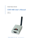
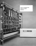
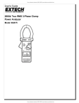
Programming and Using the Courier V.Everything Modem for
Remote Operation of DDF6000
A Technical Application Note from Doppler System
July 5, 1999
1.0 Introduction
Version 3.x of the DDF6000, running version 2.x of the BrgTrack software, allows one or more of
these direction finders to be controlled remotely over leased telephone lines. In the past, radio
modems were required for the purpose. To check which firmware version you are using, watch
the front panel display of the DDF6000 during power turn-on; to check the software version,
use the Help | About BrgTrack menu on the PC. If you are going to need an upgrade, see the
Software & Upgrade page on the web site, or seek help from your local distributor or from the
factory.
2.0 Configuration
A modem pair is required for each remote site. The "calling" modem is located at the central
control point where the PC running BrgTrack is located, and the "answering" modem is located
at the remote site. If only one remote site is needed, the PC's COM port will connect to the
sending modem using a 3-wire serial cable as shown in Figure 1. If multiple sites are to be
connected, the Serial Expander, DDF6077 should be used. See Figure 2. A Serial Expander will
interface a single PC COM port with up to three calling modems. If more than three sites are to
be connected, multiple Serial Expanders may be used. See Figure 3. (The number of sites that
may be connected using N Serial Expanders is equal to 2N + 1).
Figure 1
Figure 2
Figure 3
3.0 Courier V.Everything Modem
This modem is suitable for use as either the calling or answering modem with either leased
lines or standard dial up lines. The following discussion assumes the standard external version
of these modems. For more information on this modem, contact 3COM.
According to 3COM, the modems must be identical and have the same internal software. The
following procedure will check that the configuration is the same.
3COM also advises that the lines themselves should meet the following requirements:
The leased line should be an analog 2-wire full duplex line (3002
type D) with no conditioning. It must not be a 4-wire or digital
line. If the line is an actual dedicated line, its length should be 5
miles or less. If it is a true leased line with power provided by the
telephone central office, then there is no limit on the length.
Note that the cables and DIP switch settings used for modem setup are different from those
used during normal modem operation with the DDF6000.
4.0 Modem Setup
4.1 Modem to PC Cable
Note the serial connector used on your PC. It will be either a DE9 male or a DB25 male
connector. When setting up the modems, you should use a serial cable and/or adapter that
contains all of the RS232 handshake lines. If the PC has a 25 pin connector, use a standard DB25
male to DB25 female 25-conductor shielded cable. If the PC has a 9 pin connector, use a
standard DE9 male to DE9 female 9-conductor shielded cable with a DE9 female to DB25 male
adapter at the modem end.
4.2 PC Setup
Run the Windows 95 Hyper Terminal program (Start | Programs | Accessories |
HyperTerminal). Set the communications parameters from the Terminal Program Properties
menu which is accessed by selecting File | Properties. On the Tab called Phone Number, change
the Connect using box to read "Direct to COM n" where n is the COM port available on your PC.
Click on Configure and set the Port Settings for Bits per second = 2400, Data Bits = 8, Parity =
None, Stop bits = 1, and Flow control = Hardware. Check OK to return to the Terminal Program
Properties menu.
Select the tab marked Settings and select ASCII Setup. Deselect all the option boxes and click on
OK. Click on OK again to return to the Hyper Terminal program screen.
With the modem power off, set the DIP switches on the modem so that switches 3, 5, 8, and 10
are down (ON) and all other switches are up (OFF). Do this for all of the modems to be used.
When the modem power is turned on, this will load the factory default settings into the
modem.
Connect one of the modems to the PC using the cable described in section 4.1. Do not connect
the RJ11 telephone cable.
Turn the modem power on, wait a few seconds, then type AT<enter>. You should obtain the
response OK from the modem.
4.3 Check Modem Software Configuration
Select Transfer | Capture to Printer and type ATI7<enter>. The screen should fill with a listing of
the modem software configuration. Select Transfer | Capture to Printer again. This will cause
the information on the screen to be printed.
Turn off the modem, disconnect the RS232 cable, connect the second modem to this cable, and
turn it on. Repeat the above procedure to print out the software configuration.
Repeat for the other modems to be used in the DF network.
Compare the printed records. The same information should appear in the Option line, the Clock
Frequency, and the Supervisor Rev. If the records are different, you should update the software
in one or more of the modems so that all versions are identical. See the User manual and/or
contact 3COM for information on obtaining the latest software and installing it.
4.4 Calling Modem with Leased Line
Locate a modem that will be used at the PC (a calling unit). It is a good idea to mark this modem
to distinguish it from the answering modems. Connect it to the PC using the same setup
described in section 4.3. Verify that the program is communicating with the modem by typing
AT <enter> and seeing that the modem responds with OK.
Enter the following command line from the Hyper Terminal program:
AT&F0&M0&B1&N3&L1S7=10S44=2&W<enter>
The modem should respond with OK. If it does not, check the command line and enter it again.
Turn the modem power off, and set the DIP switches so that switches 1, 4 and 5 are down (ON)
and all other switches are up (OFF). The new settings will take effect when the modem is turned
back on.
Repeat for all additional calling modems.
4.5 Answering Modem with Leased Line
Locate a modem that will be used at the DF site (the answering unit). Connect it to the PC using
the same setup described in section 4.3. Verify that the program is communicating with the
modem by typing AT <enter> and seeing that the modem responds with OK.
Enter the following command using Hyper Terminal:
AT&F0&M0&B1&N3&L1S7=10S44=2&W<enter>
The modem should respond with OK. If it does not, check the command line and enter it again.
Turn the modem power off, and set the DIP switches so that switches 1 and 4 are down (ON)
and all other switches are up (OFF). The new settings will take effect when the modem is turned
back on.
Repeat for all additional answering (DF site) modems.
Note that the setup strings used in both calling and answering modems cause the modems to
communicate at 2400 baud at both the serial port and over the telephone line, error
checking/correction is disabled, and flow control is also disabled.
4.6 Calling Modem with Dialup Line
Locate a modem that will be used at the PC (a calling unit). Connect it to the PC using the same
setup described in section 4.3. Verify that the program is communicating with the modem by
typing AT <enter> and seeing that the modem responds with OK.
Enter the following command using Hyper Terminal:
AT&F0&M0&B1&N3S69=2&Z0=xxxxxxxDTS13=16&W<enter>
The modem will not answer with an OK to this setup string, but if you have made a mistake, it
will answer with ERROR.
In place of xxxxxxx enter the phone number of the remote site to be called by this modem.
Label the modem "Dials xxxxxxx".
It is strongly recommended that the modems be tested for operation before locating them to
remote sites as described in Section 5 below. You may want to program a temporary "local" dial
up number to perform these tests, then reprogram the calling modems to the permanent
phone number of the remote site.
Turn the modem power off, and set the DIP switches so that switches 1, 4 and 5 are down (ON)
and all other switches are up (OFF). The new settings will take effect when the modem is turned
back on.
Repeat for all additional calling modems.
4.7 Answering Modem with Dialup Line
Locate a modem that will be used at the DF site (the answering unit). Connect it to the PC using
the same setup described in section 4.3. Verify that the program is communicating with the
modem by typing AT <enter> and seeing that the modem responds with OK.
Enter the following command using Hyper Terminal:
AT&F0&M0&B1&N3&W<enter>.
The modem will answer with an OK.
Turn the modem power off, and set the DIP switches so that switches 1 and 4 are down (ON)
and all other switches are up (OFF). The new settings will take effect when the modem is turned
back on.
Repeat for all additional answering (DF site) modems.
Note that the setup strings used in both calling and answering modems cause the modems to
communicate at 2400 baud at both the serial port and over the telephone line, error
checking/correction is disabled, and flow control is also disabled.
5.0 Modem Operation
5.1 Calling Modem to PC Cable
You can use the same cable for modem operation as used above for modem programming.
However, all that is required is a 3 wire shielded cable that connects the calling modem to the
COM port on the PC.
Signal
PC DB25 (female) pin PC DE9 (female) pin Calling modem DB25 (male) pin
TXD
2
3
2
RXD
3
2
3
Ground 7
5
7
5.2 Answering Modem to DDF6000 Cable
A 3-wire shielded cable is required that connects the following signals on the answering modem
to J1 on the DDF6000.
Signal
Answering modem DB25 (male) pin DDF6000 J1 (female) pin
TXD
3
3
RXD
2
2
Ground 7
5
5.3 Testing the Modems
Connect a DDF6000 to an Answering Modem and connect a Calling Modem to the PC. If you
have set up the modems for leased line operation, connect the two modems together with a
length of telephone cable having RJ11 plugs, such as the short length supplied with the
modems. If you have set up the modems for dial up operation, connect them to two separate
phone lines with the answering modem connected to the one with the phone number
programmed into the sending modem. Use the RJ11 jacks marked "Jack" (closest to the RS232
connectors) on the modems. Turn the modems on. After a few seconds of handshaking the two
modems will connect. When this happens, the CD, OH, MR and CS lights on both modems will
be lit and the AA light will be lit on the answering modem.
Be sure that a plug is inserted in J4 on the DDF6000 to place it in the CIV mode. Turn on the
power to the direction finder with the plug installed. To test the network, you do not need to
have a receiver or direction finder antenna connected. You can place the direction finder in a
"self test" mode by selecting (from the front panel) Sweep = 0, Cal = ON, Sig = 9). The DF should
display a bearing. When you finish these tests, you can turn off the self test mode using the
same command sequence.
Execute BrgTrack on the PC. Check that the proper COM port has been selected (Setup | Serial
Port), then check that the DF address matches that of the DDF6000 connected. (The default
value is 1). Select Setup | Site, Enable one site, select Modify, and set the DF-id to the address
of the DDF6000. If a CIV receiver is connected to the DDF6000, check that its address also
matches that shown in the RX-id field. Select Locate on Map and be sure that the site location is
shown somewhere on the screen. If a CIV receiver is not connected to the DF, be sure that no
channels are enabled (Setup | Channels | Disable).
Now place BrgTrack in the RUN mode. The RD and SD lights on both modems should blink and
the BrgTrack screen should display a bearing.
To verify that the system will restart after a power failure, turn the DDF6000 Off. BrgTrack will
display an error message. Turn the DDF6000 back ON then click on "Yes" to restart BrgTrack's
polling sequence.
Turn off the power on the answering modem. BrgTrack will again display an error message and
after brief interval, the CD light on the calling modem will go off. Turn the power back on and
wait until the calling modem light returns to on. This may take anywhere from a few seconds
with a leased line connection to 15 or more seconds with a dial up line. Now click the "Yes"
button to restart BrgTrack.
Turn off the power on the calling modem, turn it back on, and wait for the CD light to indicate
that the modems have reestablished communication. Restart BrgTrack using the Yes button.
If you will be connecting to multiple sites, repeat the above tests using the next modem pair.
5.4 Testing Multiple Modem Connections
Before testing multiple modems and DF's you need to set the addresses of each DDF6000 to a
unique value using the RDFCMD program provided with the direction finders. Connect a
DDF6000 to the PC serial port (using a minimum 3-wire cable), execute RDFCMD, select the
proper COM port, select DF serial port J1, select CIV protocol, enter the current CIV address (1
unless you have already changed it), and enter anything for the receiver CIV address.
Enter command 0 (Bearing Data Rqst) and verify that the a response message is received. To
change the CIV address, enter command 4 from the Main menu to reach the RDF Address
Menu, enter the new CIV address, then hit the ESC key twice to exit the program.
If you will be using CIV receivers at each site, you need to also set unique addresses on these.
Refer to the ICOM receiver manual for instructions on setting the CIV addresses.
Connect the female connector on the serial data expander to the PC using the cable provided
with it (a six foot 3 conductor shielded DE9 male to DE9 female), and connect the calling
modems to the male connectors on the serial data expander.
With BrgTrack in its off mode, setup the CIV addresses for the direction finders and receivers at
each site to match those connected to the network.
Turn all the direction finders and modems on and wait until all the modems are communicating
properly as indicated by stable CD indications on the calling modems. Now click on Run in
BrgTrack. You should see bearings displayed at each site (assuming that all direction finders are
still in the self test mode).
6.0 Timing
The following timing diagrams are provided as an aid in case you experience difficulty with
communications after setting up the modems. Figure 4 shows the timing obtained using the
Courier V.Everything modem on a leased line. Figure 5 illustrates the timing that results when a
direct (local) connection is made between the PC and the DDF6000.
Figure 4
Figure 5
7.0 Final Installation
When all of the modems, direction finders, receivers, serial data expanders and the PC are
operating reliably in the same room, you are ready to locate the answering modems, direction
finders and receivers to the remote sites. Be sure to note the CIV addresses of the direction
finders and the receivers so that they are installed at the correct site location. Also, be sure not
to mix up the calling and answering modems. Remember to switch off the self test mode on the
direction finders.