1
Version 1.6
ArcSource Inground 24 MC Integral
Table of contents
1. Safety instructions ...................................................................................................................................................... 3
2. Fixture exterior view ................................................................................................................................................... 4
3. Installation .................................................................................................................................................................. 4
3.1 Mounting .............................................................................................................................................................. 4
3.2 Beam tilt adjustment ............................................................................................................................................ 7
3.3 Setting and control ............................................................................................................................................... 7
3.4 Wireless DMX operation ....................................................................................................................................... 9
4. ArcSource Inground 24 MC Integral - DMX protocols ..............................................................................................10
4.1 RGBW version .....................................................................................................................................................10
4.2 SW version ..........................................................................................................................................................11
4.3 Single colour version...........................................................................................................................................12
5. Control menu map ....................................................................................................................................................13
5.1 RGBW version .....................................................................................................................................................13
5.2 SW version ..........................................................................................................................................................16
5.3 Single colour version...........................................................................................................................................18
6. Fixture menu.............................................................................................................................................................21
6.1 Fixture Address ...................................................................................................................................................22
6.2 Fixture information .............................................................................................................................................22
6.3 Personality ..........................................................................................................................................................23
6.4 Manual mode......................................................................................................................................................23
6. 5 Test sequences...................................................................................................................................................24
6.6 Stand-alone setting.............................................................................................................................................24
6.7 Special functions .................................................................................................................................................25
7. RDM ..........................................................................................................................................................................26
8. Technical specifications ............................................................................................................................................28
10. Cleaning and maintenance .....................................................................................................................................30
2
ArcSource Inground 24 MC Integral
FOR YOUR OWN SAFETY, PLEASE READ THIS USER MANUAL CAREFULLY
BEFORE POWERING OR INSTALLING YOUR ArcSource Inground 24 MC Integral !
Save it for future reference.
This device has left our premises in absolutely perfect condition. In order to maintain this condition and to ensure a
safe operation, it is absolutely necessary for the user to follow the safety instructions and warning notes written in
this manual.
The manufacturer will not accept liability for any resulting damages caused by the non-observance of this manual
or any unauthorized modification to the device.
Please consider that damages caused by manual modifications to the device are not subject to warranty.
1. Safety instructions
DANGEROUS VOLTAGE CONSTITUTING A RISK OF ELECTRIC SHOCK IS PRESENT WITHIN THIS UNIT!
Make sure that the available voltage is not higher than stated on the fixture.
This fixture should be operated only from the type of power source indicated on the marking label. If you are not
sure of the type of power supplied, consult your authorized distributor or local power company.
Always disconnect the fixture from AC power before removing housing.
Do not install the unit near naked flames.
Refer servicing to qualified service personnel.
This fixture falls under protection class I. Therefore this fixture has to be connected to a mains socket outlet with
a protective earthing connection.
Do not connect this fixture to a dimmer pack.
LED light emission. Risk of eye injury.
Do not look straight at the fixture´s LEDs during operation. The intense light beam may damage your eyes.
Avoid brute force when installing the fixture.
The fixture was designed for outdoor use. This fixture must not be used for underwater installation.
When choosing the installation spot, please make sure that the fixture is not exposed to extreme heat or dust.
Avoid using the unit in locations subject to possible impacts.
Only operate the fixture after having checked that the housing is firmly closed and all screws are tightly fastened.
The fixture becomes hot during operation. Allow the fixture to cool approximately 20 minutes prior to manipulate
with it.
Operate the fixture only after having familiarized with its functions. Do not permit operation by persons not
qualified for operating the fixture. Most damages are the result of unprofessional operation!
Please consider that unauthorized modifications on the fixture are forbidden due to safety reasons!
Please use the original packaging if the fixture is to be transported.
3
ArcSource Inground 24 MC Integral
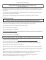
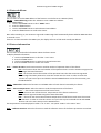
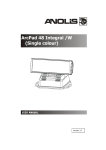
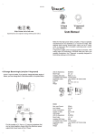
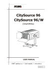
2. Fixture exterior view
1. Temporary cover
2. Installation sleeve
3. Aperture for cables
4. Flange
5. Body of the ArcSource Inground 24 MC Integral
6. Junction box
3. Installation
3.1 Mounting
Fixtures must be installed by a qualified electrician in accordance with all national
and local electrical and construction codes and regulation.
The ArcSource Inground 24 MC is controlled via DMX 512 serial digital signal. It is indispensable to use cables
that meet EIA RS-485 specifications to connect the fixture to the control console.
Warning!
If the ArcSource Inground 24 MC Integral will be exposed max. allowed static load, the subsoil of the installation
sleeve has to withstand load of 35kN.
4
ArcSource Inground 24 MC Integral
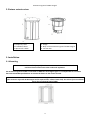
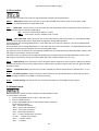
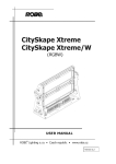
1. Prepare an adequate hole with a good drainage at its bottom, insert the installation sleeve (1) into the hole and
unscrew the temporary cover (2) from the installation sleeve.
2. Connect the power cable and DMX cable to the a junction box (3) of the ArcSource Inground 24 MC Integral (4).
The apertures (9) serve for passing of cables.
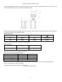
Power connection
L
N
EU
Braun
Blue
Green/yellow
US
Black
White
Green
This device falls under class one and must be grounded!
DMX connection
+
0
-
Data +
Data ground(shielding)
Data -
Base technical features of the ABB terminal blocks:
Type: DS 2,5/10.4L (4 springs mini blocks)
Parameter
IEC
UL/SCA
Rated voltage
800 V
600 V
Rated current
24 A
15 A
Wire size rated/gauge
2.5mm2/A2
12AWG
Wire stripping length
9.5 mm
Remove end caps from cable glands before passing cables into the junction box. Two reducing seal allows to
reduce a hole diameter of the cable glands.
Cable gland clamping range (ø min-max): 6-12 mm
5-9 mm (with reducing seal)
5
ArcSource Inground 24 MC Integral
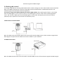
After connection needed cables, screw the cover of the junction box with four screw using a tightening torque of
8Nm. Check that all bushings and screws are firmly screwed.
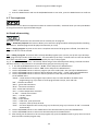
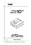
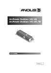
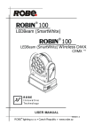
3. Insert the ArcSource Inground 24 MC Integral (4) into the installation sleeve (1) and adjust it to desired position.
Note: There is a projection (A) and the pad (D) on the sleeve housing and the notches (C) on the ArcSource
Inground 24 MC Integral in order to facilitate adjusting of the ArcSource Inground 24 MC Integral towards the
sleeve. The centre of the notches (C) on the ArcSource Inground 24 MC Integral also indicates the axis around
which the LED module tilts.
If units are installed in a row, keep the projection (A) on the sleeve housing on the same side at all units to keep the
same direction of tilting of LED module.
6
ArcSource Inground 24 MC Integral
4. Secure the ArcSource Inground 24 MC Integral in desired position by means of the four Allen screws M6x30mm
(5).
5. Insert top flange (6) on the ArcSource Inground 24 MC Integral and screw it on the sleeve (1) by means of the six
screws M6x35mm (7). The screws must be tightened securely and uniformly, tightening first one and then the one
diametrically opposite to it.
After connecting the ArcSource Inground 24 MC Integral to mains, set desired tilt of the LED module.
3.2 Beam tilt adjustment
The fixture beam can be tilted ±15° from a vertical axis by means of the item “tilt” in the fixture menu (SPECtilt).
Adjusted position of the LED module is permanent kept ,also after disconnected the fixture from mains. During the
tilt adjustment, a white beam will appear.
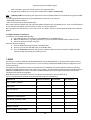
3.3 Fixture with asymmetric lenses
Differentiation of fixtures with asymmetric lenses and shape of light output.
7
ArcSource Inground 24 MC Integral
3.4 Setting and control
For setting DMX address, selecting DMX mode and for another settings you need either Robe Universal Interface
WTX or the RDM Communicator. Please see the Robe Universal Interface WTX or RDM Communicator user
manuals to get more information about this products.
For ArcSource Inground 24 MC equipped with wireless DMX module: after switching the fixture on, the fixture
waits for DMX signal on “wire” input for 30 sec. If no DMX signal is present, fixture starts switching between
“wire” and “wireless” DMX input until finds DMX signal on some input. During this process fixture´s effects
(channels) stay in positions set in the menu Init Positions (In.Po).
1.Robe Universal Interface WTX
Note: the Robe Universal Interface WTX can be also used for wireless DMX version of the ArcSource Inground 24
MC Integral, but special control software has to be installed on your notebook.
2. RDM Communicator
Note: the RDM Communicator cannot be used for wireless DMX version of the ArcSource Inground 24 MC Integral.
8
ArcSource Inground 24 MC Integral
3.5 Wireless DMX operation
The wireless version of the ArcSource Inground 24 MC Integral is equipped with the Lumen Radio CRMX module
and antenna for receiving DMX signal. CRMX module operates on the 2.4 GHz band.
To link the fixture with DMX transmitter.
The fixture can be only linked with the transmitter by running the link procedure at DMX transmitter .
After linking , the level of DMX signal ( 0-100 %) is displayed in the menu
item “SiGn.“ (SPEC-->rAdI.--> SiGn.)
Note: If DMX signal has been sending to fixture via cable (“wire DMX”) , the signal (cable) has to be
disconnected from the fixture before linking to DMX transmitter.
To unlink the fixture from DMX transmitter.
The fixture can be unlinked from transmiter via the menu item “ unLi.“ (SPEC-->rAdI.--> unLi.).
Direct visibility between a transmitter and the ArcSource Inground 24 MC Integral must be ensured.
The minimum angle between the ground with the ArcSource unit and transmitter´s antenna is 10°.
Distance between a DMX transmitter and the ArcSource unit depends on transmission range of used DMX
transmitter (we recommend to test behaviour of DMX transmitter with the ArcSource Inground
24 MC Integral before installation).
9
ArcSource Inground 24 MC Integral
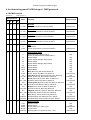
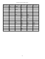
4. ArcSource Inground 24 MC Integral - DMX protocols
4.1 RGBW version
Version 1.0
Default mode: 3
Mode/Channel
1
2
3
4
-
1
1
1
-
1
2
3
-
-
2
3
4
-
-
Value
Function
0 - 255
Red LEDs
Red LEDs saturation control (0-100%)
proportional
0 - 255
Green LEDs
Green LEDs saturation control (0-100%)
proportional
0 - 255
Blue LEDs
Blue LEDs saturation control (0-100%)
proportional
0 - 255
White LEDs
White LEDs saturation control (0-100%)
proportional
0
1-255
CT0
No function
Colour temperature correction (0-100%)
proportional
2
3
4
5
6
Type of control
Virtual colour wheel
No function (for DMX mode 4)
White (R+G+B+W=full for DMX mode 1)
1-2
White 2700 K
3
White 2700 K (Halogen lamp mode)
4-5
White 3200 K
6
White 3200 K (Halogen lamp mode)
7-9
White 4200 K
10-12
White 5600 K
13-15
White 8000 K
16
Blue (Blue=full, Red+Green+White=0)
17-55
Red=0, Greenup,Blue =full, White=0
56
Light Blue (Red=0, Green=full, Blue =full, White=0)
57 - 95
Red=0, Green=full, Bluedown, White=0
96
Green (Red=0, Green=full, Blue =0, White=0)
97 – 134 Redup, Green=full, Blue=0, White=0
135
Yellow-green (Red=full, Green=full, Blue=0, White=0)
136 - 174 Red=full, Greendown, Blue=0, White=0
175
Red(Red=full, Green=0, Blue=0, White=0)
176 -214 Red=full, Green=0, Blueup, White=0
215
Magenta (Red=full, Green=0, Blue=full, White=0)
216 – 246 Reddown, Green=0, Blue=full, White=0
247
Blue (Red=0, Green=0, Blue=full, White=0)
248-251 Rainbow effect with fade time (fast slow)
252-255 Rainbow effect without fade time (fast slow)
step
step
step
step
step
step
step
step
proportional
step
proportional
step
proportional
step
proportional
step
proportional
step
proportional
step
proportional
proportional
Shutter/ Strobe
Shutter closed
Shutter open
Strobe-effect from slow to fast
Shutter open
Opening pulses in sequences slow--> fast
step
step
proportional
step
proportional
0
-
-
-
7
0-31
32-63
64-95
96-127
128-143
10
step
ArcSource Inground 24 MC Integral
2
-
-
-
-
144-159
160-191
192-223
224-255
Closing pulses in sequences fast --> slow
Shutter open
Random strobe-effects from slow to fast
Shutter open
proportional
step
proportional
step
0 - 255
Dimmer
Dimmer intensity from 0% to 100%
proportional
0 - 255
Dimmer fine
Fine dimmer intensity from low to high
8
9
Proportional
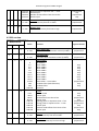
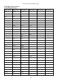
4.2 SW version
Version 1.0
Default mode: 1
Mode/Channel
1
2
3
1
-
1
2
-
-
-
1
-
2
Value
Function
0 - 255
Warm white LEDs
Warm white LEDs saturation control (0-100%)
proportional
0 - 255
Cool white LEDs
Cool white LEDs saturation control (0-100%)
proportional
0
1-2
3-4
5-6
7-8
9-10
11-12
13-14
15-16
17-247
248
249
250-255
Colour wheel
No function
White 2800 K
White 3200 K
White 3800 K
White 4200 K
White 4600 K
White 5000 K
White 5600 K
White 6300 K
Warm white --> Cool white
Rainbow effect (with fade time)
Rainbow effect
Reserved
0-31
32-63
64-95
96-127
128-143
144-159
160-191
192-223
224-255
Strobe
Shutter closed
Shutter open
Strobe-effect from slow to fast
Shutter open
Opening pulses in sequences slow--> fast
Closing pulses in sequences fast --> slow
Shutter open
Random strobe-effects from slow to fast
Shutter open
step
step
proportional
step
proportional
proportional
step
proportional
step
0 - 255
Dimmer
Dimmer intensity from 0% to 100%
proportional
0 - 255
Dimmer fine
Fine dimmer intensity from low to high
proportional
2
3
4
5
6
-
-
Type of control
11
step
step
step
step
step
step
Step
step
proportional
step
step
ArcSource Inground 24 MC Integral
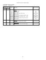
4.3 Single colour version
Version 1.0
Default mode: 1
Mode/Channel
Value
1
2
-
1
1
-
Type of control
0-31
32-63
64-95
96-127
128-143
144-159
160-191
192-223
224-255
Strobe
Shutter closed
Shutter open
Strobe-effect from slow to fast
Shutter open
Opening pulses in sequences slow--> fast
Closing pulses in sequences fast --> slow
Shutter open
Random strobe-effects from slow to fast
Shutter open
step
step
proportional
step
proportional
proportional
step
proportional
step
0 - 255
Dimmer
Dimmer intensity from 0% to 100%
proportional
0 - 255
Dimmer fine
Fine dimmer intensity from low to high
proportional
2
3
Function
12
ArcSource Inground 24 MC Integral
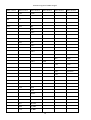
5. Control menu map
5.1 RGBW version
Default settings=Bold print
Menu Level 1
Menu Level 2
Menu Level 3
A001
dM.Ad.
001-512
InFo
Poti.
totL
Menu Level 4
rSEt
DM.In.
rEd
0-255
:
tEMP.
F.dim
0-255
Cur.t.
tEM.b.
Hi.tE.
tEM.L.
rSEt
VErS.
IC1
IC2
PErS
dM.Pr.
Mod.1
Mod.2
Mod.3
Mod.4
rAd.t.
OFF, 1-25.5 hrs
M. F.ti
0.1-25.5
rGb.C.
On, Off
tEM.U.
°C, °F
In.Po.
rEd1
0-255
:
F.dim
0-255
Stor.
dFSE
13
Menu Level 5
Menu Level 6
ArcSource Inground 24 MC Integral
Menu Level 1
Menu Level 2
Menu Level 3
Menu Level 4
Menu Level 5
Menu Level 6
MAn.M.
rEd
0-255
PrG.1
St.01
P.End
1-40
:
:
rEd
0-255
PrG.3
St.68
:
:
F.din
0-255
F.tin.
0-25,5 sec
S.tin.
0-25.5 sec
:
F.din
tESt
run
St.AL.
Auto
0-255
Off
tESt
PrG.1
:
PrG.3
PLAY
tESt
PrG.1
:
PrG.3
Edit
CoPY
SPEC.
rdML
rdMH
t.LEd
rGbU
SI.Co.
SM.Uh.
rAdI
SiGn.
unLi
I.bLi.
On, OFF
HOLd
On, Off
14
ArcSource Inground 24 MC Integral
Menu Level 1
Menu Level 2
Menu Level 3
F.FrE
On,OFF
Menu Level 4
Menu Level 5
Menu Level 6
tilt
Adj.
Man.M.
rEd
:
F.din
CaL.C.
rEd. C.
0-255
GrE.C.
0-255
bLu.C.
0-255
UhI.C.
0-255
SAUE
CAL.t.
2700
rEd.C.
0-255
3200
GrE.C.
0-255
4200
bLu.C.
0-255
5600
UhI.C.
0-255
8000
uPd.
15
ArcSource Inground 24 MC Integral
5.2 SW version
Default settings=Bold print
Menu Level 1
Menu Level 2
Menu Level 3
A001
dM.Ad.
001-512
InFo
Poti.
totL
Menu Level 4
rSEt
DM.In.
rEd
0-255
:
tEMP.
F.dim
0-255
Cur.t.
tEM.b.
Hi.tE.
tEM.L.
rSEt
VErS.
IC1
IC2
PErS
dM.Pr.
Mod.1
Mod.2
Mod.3
rAd.t.
OFF, 1-25.5hrs
M. F.Time
0.1-25.5
tEM.U.
°C, °F
In.Po.
UU
0-255
:
F.dim
0-255
Stor.
dFSE
MAn.M.
UU
0-255
:
F.din
0-255
16
Menu Level 5
Menu Level 6
ArcSource Inground 24 MC Integral
Menu Level 1
Menu Level 2
tESt
run
St.AL.
Auto
Menu Level 3
Menu Level 4
Menu Level 5
Menu Level 6
PrG.1
St.01
P.End
1-40
:
:
UU
0-255
PrG.3
St.68
:
:
F.din
0-255
F.tin.
0-25,5 sec
S.tin.
0-25.5 sec
Off
tESt
PrG.1
:
PrG.3
PLAY
tESt
PrG.1
:
PrG.3
Edit
CoPY
SPEC.
rdML
rdMH
t.LEd
rGbU
SI.Co.
SM.Uh.
rAdI
SiGn.
unLi
I.bLi.
On, OFF
HOLd
On, Off
F.FrE
On,OFF
tilt
uPd.
17
ArcSource Inground 24 MC Integral
5.3 Single colour version
Default settings=Bold print
Menu Level 1
Menu Level 2
Menu Level 3
A001
dM.Ad.
001-512
InFo
Poti.
totL
Menu Level 4
rSEt
DM.In.
Stro
0-255
:
tEMP.
F.din
0-255
Cur.t.
tEM.b.
Hi.tE.
tEM.L.
rSEt
VErS.
IC1
IC2
PErS
dM.Pr.
Mod.1
Mod.2
rAd.t.
OFF, 1-255 min.
M. F.Time
0.1-25.5
tEM.U.
°C, °F
In.Po.
Stro
0-255
:
F.dim
0-255
Stor.
dFSE
MAn.M.
Stro
0-255
:
18
Menu Level 5
Menu Level 6
ArcSource Inground 24 MC Integral
Menu Level 1
Menu Level 2
Menu Level 3
F.din
0-255
tESt
run
St.AL.
Auto
Menu Level 4
Menu Level 5
Menu Level 6
PrG.1
St.01
P.End
1-40
:
:
Stro
0-255
PrG.3
St.68
:
:
F.din
0-255
F.tin.
0-25,5 sec
S.tin.
0-25.5 sec
Off
tESt
PrG.1
:
PrG.3
PLAY
tESt
PrG.1
:
PrG.3
Edit
CoPY
SPEC.
rdML
rdMH
t.LEd
rGbU
SI.Co.
SM.Uh.
rAdI
SiGn.
unLi
I.bLi.
On, OFF
HOLd
On, Off
F.FrE
On,OFF
19
ArcSource Inground 24 MC Integral
Menu Level 1
Menu Level 2
Menu Level 3
Menu Level 4
tilt
uPd.
20
Menu Level 5
Menu Level 6
ArcSource Inground 24 MC Integral
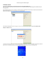
6. Fixture menu
To browse the fixture menu, use the Robe Universal Interface WTX (RUNIT VTX).
Note: connect the RUNIT WTX with the junction box via shielded twisted-pair cable designed for RS-485 and 5-pin
XLR-plug (male).
Run the RDM-network on your computer and click with the right button of the mouse on the fixture and select the
Remote LED display option from the menu list as shown below.
The Remote LED Display window will appear. Now you can fully control the fixture using the UP, Down, Enter,
Escape and Reset buttons.
To browse the fixture menu, use can also use the RDM communicator, connect the RDM communicator with the
junction box via shielded twisted-pair cable designed for RS-485 and 3-pin or 5-pin XLR-plug (male).
21
ArcSource Inground 24 MC Integral
6.1 Fixture Address
Use this menu to set the DMX address of the fixture or set the fixture as a Master (Slave).
dM.Ad. --- DMX addressing. Select this submenu to set a DMX start address.
To set a DMX address.
1. Use the UP/DOWN buttons to find “ A001“ menu.
2. Press the ENTER button.
3. Use the UP/DOWN buttons to select desired start address.
4. Press the ENTER button to confirm the choice.
Note: After switching on, the ArcSource Inground 24 MC Integral will automatically detect whether DMX 512 data
is received or not.
If there is no data received at the DMX input, the display will start to flash with actually set address.
6.2 Fixture information
Use this menu to read useful information about the fixture status.
To display desired information.
1. Use the UP/DOWN buttons to find the “ InFo“ menu.
2. Press the ENTER button.
3. Use the UP/DOWN buttons to select the required menu item.
4. Press the ENTER button to confirm the choice.
Po.ti. ---Power On Time. Use the menu item to read the number of operation hours of the fixture.
totL - the function shows the total number of the operation hours since the ArcSource Inground 24
MC Integral has been fabricated.
rESEt - the function shows the number of the operation hours that the ArcSource Inground
24 MC Integral has been powered on since the counter was last reset. In order to reset this
counter to 0 you have to press and hold the UP and DOWN buttons and at the same time press
the ENTER button.
DM.In.---DMX values. Select this function to read DMX values of each channel received by the fixture.
tEMP --- Fixture Temperatures. Select this menu to read the temperatures of the fixture:
Cur.t. --- the current temperature of the fixture inside.
Hi.tE. - the menu item shows the max. temperatures of the fixture inside since
the ArcSource Inground 24 MC Integral has been fabricated.
rSEt --- the menu item shows the maximum temperatures of the fixture inside since the counter
was last reset. In order to reset this counter to 0 you have to press and hold the UP and DOWN
buttons and at the same time press the ENTER button.
The temperatures can be displayed in either °C or °F units - see option “tEM.U“ in the menu “Pers“.
VErS. ---Software Versions. Select this function to read the software version of the fixture processors IC1 and IC2.
22
ArcSource Inground 24 MC Integral
6.3 Personality
Use this menu to modify the ArcSource Inground 24 MC Integral operating behaviour.
DM.Pr. --- DMX preset. Select this menu item to set a desired DMX mode. Please refer to the chapter "DMX
protocol" for detail description of each DMX mode.
rAd.t. --- Unlink time. Use this menu to set time after that the linked fixture will be unliked from the transmitter, if
the transmitter does not transmit DMX signal.
Off --- Fixture is unlinked after 100 hrs (+/-10%).
1-255. --- Time from 1-25.5 hrs. Default value is 1 hour.
M. F. ti --- Max. Fade time. Select this menu item to set a desired max. fade time (0-25.5 sec.). This adjusted fade
time influences fade of Red, Green, Blue,White and dimmer during DMX operation:
If time between two receiving DMX values is > than fade time set in the item “M Ftime“, the entire adjusted fade
time will be used.
If time between two receiving DMX values is < than fade time set in the item“M Ftime“, the adjusted fade time will
be reduced to fill entire time between the two receiving DMX values.
e.g “M Ftime“=2sec. and fixture has received Red=0 DMX, after 5 seconds will receive Red=255 DMX. It means, that
red will go to full intensity during 2 seconds.
“M Ftime“=8 sec. and fixture has received Red=0 DMX, after 5 seconds will receive Red=255 DMX. It means, that
red will go to full intensity during 5 seconds. (Max, fade time is reduced from 8 sec. to 5 sec.).
rGb.C. --- RGB counting. If this function is active, the white channel (channel 4) uses red, green and blue chanels in
proportional relation to ensure max. light output in a white colour ( if white channel =full, also red, green and blue
channels are full).
tEM.U. --- Temperature Unit. Use this menu in order to display the fixture temperatures in desired units: °C or °F.
In.Po. --- Init effect positions. Use this function to set all effects to the desired positions to which they will move
after switching the fixture on (if DMX is not being received).
dF.SE. --- Default Settings .The menu item sets all fixture parameters to the default (factory) values.
6.4 Manual mode
Use this menu for control the fixture without connected DMX console.
To control fixture channels.
1. Use the UP/DOWN buttons to find “ Man.M“ menu.
2. Press the ENTER button.
3. Use the UP/DOWN buttons to select desired effect (channel).
List of control channels:
“rEd” - red LEDs saturations
“GrEn“ - green LEDs saturations
“bLuE“ - blue LEDs saturations
“Uhi“ - white LEDs saturations
“CtC“ – a colour temperature correction
“C. UhE“ - a virtual colour wheel
“Stro.“ - a strobe, shutter
“dinr“ - a dimmer
23
ArcSource Inground 24 MC Integral
“F.din” - a fine dimmer
4. Press the ENTER button and use the UP/DOWN buttons to set value , press the ENTER button to confirm it.
5.
6. 5 Test sequences
Use this menu to run demo-test sequences without an external controller, which will show you some possibilities
of using the ArcSource Inground 24 MC Integral.
6.6 Stand-alone setting
The fixture is not connected to the controller but can execute pre-set program.
Auto. --- Automatic playback. This function allows you to select the program which will be played after switching
the fixture on. Selected program will be played continuously in a loop.
PLAY --- Playing program. By enter to this menu a complete overview of all programs is offered, from which the
program to be run can be selected.
Edit --- Editing a program. The fixture offers 3 freely editable programs (PrG.1, PrG.2, PrG.3) each up to 40 steps.
Every program step includes a fade time (F.tin.) - the time taken by the step´s channel status to reach the desired
level and a step time (S.tin.) - the total time occupied by the step in the program.
E.g. If “F.tin.“=5 second and “S.tin.“=20 second, effects will go to the desired position during 5 seconds and after
that they will stay in this position for 15 seconds before going to the next prog. step
1. 1. Use the UP/DOWN buttons to find “ St.AL.“ menu and press the ENTER button.
2. Use the UP/DOWN buttons to select “Edit“ menu and press the ENTER button.
3. Use the UP/DOWN buttons to select a program you want to edit (PrG.1-PrG.3 and press ENTER button.
4. Use the UP/DOWN buttons to select a desired program step ("St.01" - "St.40") and press ENTER button.
5. Use the UP/DOWN buttons to select a channel you want to edit and press the ENTER button.
List of editable items:
“P.End” - a total number of the program steps (value 1-40). This value should be set before start
programming (e.g. if you want to create program with 10 steps, set P.End=10).
“rEd” - red LEDs saturations
“GrEn“ - green LEDs saturations
“bLuE“ - blue LEDs saturations
“Uhi“ - white LEDs saturations
“CtC“ – a colour temperature correction
“C. UhE“ - a virtual colour wheel
“Stro.“ - a strobe, shutter
“dinr“ - a dimmer
“F.din” - a fine dimmer
“F.tin.“ - a fade time, (0-25.5) seconds
“S.tin.“ - step time, value (0-25.5) seconds
“CoPY“. – this item duplicates the current prog. step to the next prog. step. The item “P.End” is increased
automatically.
6. Use the UP/DOWN buttons to set a DMX value of the channel and then press the ENTER button.
7. Use the UP/DOWN buttons to select next channel and press the ENTER button.
8. After having set all channels in the current program step, press the MODE button to go by one menu level
back and select another program step.
24
ArcSource Inground 24 MC Integral
6.7 Special functions
rdML --- Code.This menu item shows the first part of the RDM identification code.
rdMH --- Code. This menu item shows the second part of the RDM identification code.
t.LEd --- Type of LEDs. The menu serves for setting control of the fixture according colour combination of LEDs.
rGbU --- RGBW version
Si.Co. --- Single colour version
SM.Uh. --- Smart white version
Note: Do Not change the factory setting!
rAdI --- Wireless DMX (only wireless DMX version). The menu serves for reading of the wireless operation status.
SiGn. --- Signal level. The menu item shows level of received signal in %. If the fixture is not linked to the
transmitter, “no.LI” is displayed.
unLi --- Wireless DMX unlink. The item serves for unlinking the fixture from transmitter.
I. bli. --- Initial blink. If this function is on, the fixture makes auto-calibration (each LED colour lit on 100% for short
time) after switching the fixture on.
HoLd --- If the function is on, the last received DMX values are held in case that DMX data receiving was
interrupted (e.g. disconnected DMX controller).
F. FrE ---Flicker free mode. If the function is on, the light flickering visible in cameras is corrected but colour
uniformity is worse.
tilt ---Tilt of the light beam. The menu item allows to set desired tilt of the light beam. During adjusting position
of the light beam, the white beam will appear.
Adj. - Adjustment. The menu allows the fine adjustment of colours.
Man.M.- Manual mode. Use the menu to set DMX values of fixture´s channels.
Cal. C. - A calibration o red, green, blue and white colours by means of an automatic calibration
with a factory equipment (RGBW version only).
Red C – red LEDs saturation (0-255)
Grn C – green LEDs saturation (0-255)
Blu C – blue LEDs saturation (0-255)
Uhi C – white LEDs saturation (0-255)
SAUE – saves adjusted values
Cal. t. – Selection of colour temperature for manual calibration: 2700K, 3200K, 4200K, 5600K,
8000K.
Manual colour calibration:
1. Connect the fixture to the mains, unlink DMX, go to the “Man. M.” menu and set the shutter,dimmer, red,
green, blue and white channel at 255DMX and let the fixture heat up.
2. Go to the “Man. M.” menu and set the C UhE at 1 DMX (2700K)
3. Go to the “Cal t.” menu, select “2700K” item and by means of the rEd. C. , GrE. C, blu. C. and Uhi. C. items
adjust the 2700K colour temperature as exactly as possible (∆u´v´= 0).
After calibration, press the “SAUE“ item to save adjusted values.
4. Go to the “Man. M.” menu and set the C UhE at 4 DMX (3200K).
5. Go to the “ Cal t. ” menu, select “3200K” item and by means of the rEd. C. , GrE. C, blu. C. and Uhi. C.
items adjust the 3200K colour temperature as exactly as possible (∆u´v´= 0).
25
ArcSource Inground 24 MC Integral
After calibration, press the “SAUE“ item to save adjusted values.
6. Repeat this procedure for rest of colour temperatures (4200K, 5600K,8000K).
uPd. --- Updating mode.The following are required in order to update software in the ArcSource Inground 24 MC
Integral:
- PC running Windows XP/Vista/7/8 /Linux/OSX with connection to the Internet
- ROBE RDM Uploader software
- Robe Universal Interface WTX (RUNIT WTX)
Note: Both software update and case software update should execute a qualified person. If you lack qualification,
do not attempt the update yourself and ask for help your Anolis distributor.
Note: programs 1-3 and all items in the menu "PErS" and “SPEC” will be set to their default values after software
update.
To update software in the fixture
I. Installation of the ROBE RDM Uploader.
1. The RDM Uploader is available from the ROBE web site at WWW.robe.cz.
2. Make a new directory ( e.g. Robe_Uploader) on your hard disk and download the software into it.
3. Install the software on your computer.
II.Fixture software updating.
1. Connect RUNIT WTX with the fixture via DMX cable.
2. Connect your PC with the USB input of the RUNIT WTX.
3. Run the ROBE RDM Uploader and perform software update of the fixture (see the RDM Uploader
manual). Avoid interrupting the update process.
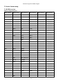
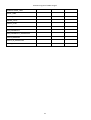
7. RDM
This fixture is ready for RDM operation.RDM (Remote Device Management) is a bi-directional communications
protocol for use in DMX512 control systems, it is the new open standard for DMX512 device configuration and
status monitoring.
The RDM protocol allows data packets to be inserted into a DMX512 data stream without adversely affecting
existing non-RDM equipment. By using a special „Start Code,“ and by complying with the timing specifications for
DMX512, the RDM protocol allows a console or dedicated RDM controller to send commands to and receive
messages from specific moving lights.
RDM allows explicit commands to be sent to a device and responses to be received from it.
The list of commands for ArcSource Inground 24 MC Integral is the following.
Parameter ID
Discovery command
DISC_UNIQUE_BRANCH
*
DISC_MUTE
*
DISC_UN_MUTE
*
SET command
GET command
DEVICE_INFO
*
SUPPORTED_PARAMETERS
*
SOFTWARE_VERSION_LABEL
*
DMX_START_ADDRESS
*
*
IDENTIFY_DEVICE
*
*
*
DEVICE_MODEL_DESCRIPTION
26
ArcSource Inground 24 MC Integral
*
MANUFACTURER_LABEL
*
DEVICE_LABEL
*
SENSOR_DEFINITION
*
SENSOR_VALUE
*
DISPLAY_LEVEL
*
DEVICE_RESET
*
DMX_PERSONALITY
*
*
*
DMX_PERSONALITY_DESCRIPTION
*
STATUS_MESSAGES
*
STATUS_ID_DESCRIPTION
*
DEVICE_HOURS
*
27
ArcSource Inground 24 MC Integral
8. Technical specifications
Power supply
• Electronic auto-ranging
• Input voltage: 100 – 277 V AC, 50-60 Hz
• Max. power consumption: 65W @ 230V (Power factor=0.83)
Optic & Effects
• Light source: 6 x LED multichip(RGBW, SW)
• Available beam angles: 7°, 24°, 34°, 42°x7° (standard), 7°x42°
• RGBW colour mixing
• Virtual colour wheel
• Adjustable strobe sequences
• Pre-set whites (2700K, 3200K, 4200K, 5600K, 8000K)
• typical Lumen maintenance: 70%@ 60,000 hours
Control
• USITT DMX 512, RDM
• DMX protocol modes: 4 (2,3,4,9 control channels)
• Operations modes: DMX, Stand-alone
• Manual control of all effects via RUNIT WTX or RDM Communicator
• 3 user editable programs each up to 40 steps.
Wireless DMX/RDM module (for wireless DMX version only: ArcSource Inground 24 MC Integral /W)
• Compliance with USITT DMX-512 (1986 & 1990) and 512-A
• Full DMX fidelity and frame integrity
• Auto sensing of DMX frame rate and frame size
• <5ms DMX latency
• Operational frequency range of 2402-2480 MHz
• Producer: LumenRadio
Strobe
• Strobe effect with variable speed (max. 20 flashes per second)
• Pre-programmed random strobe pulse-effects
Dimmer
• Smooth 16-bit dimming from 0 - 100 %
Temperatures
• Maximum surface temperature of the sleeve: +40°C
• Minimum surface temperature of the sleeve: -20°C
Overheating protection
• LED module and power source
Construction
• Housing: high pressure die cast aluminium-anodizing
• Transparent cover: tempered glass
• Flange: stainless steel 316L
• Installation sleeve: stainless steel 316L (Welded)
• silicone rubber gasket
Directionally adjustable mechanism
• Motorized tilt ±15°
28
ArcSource Inground 24 MC Integral
Weight
• 16.5 kg (8.2 kg sleeve, 8.3 kg ArcSource Inground 24 MC Integral)
Protection factor
• IP 67
Impact rating
• IK10
Static load resistance
• 35kN
Electric connection
• Junction box at bottom side of the ArcSource Inground 24 MC Integral
Included items
• 1 x ArcSource Inground 24 MC Integral
• 1 x Installation sleeve
• 1 x Installation parts (flange, screws)
• 1 x User manual
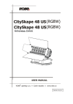
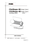
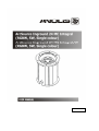
Dimensions (mm)
Sleeve with temporary cover
Sleeve + ArcSource Inground 24 MC Integral
29
ArcSource Inground 24 MC Integral
10. Cleaning and maintenance
DANGER !
Disconnect from the mains before starting any maintenance work.
Wash the transparent cover with a soft brush or sponge and a mild, non-abrasive washing detergent. Rinse it.
Maintenance and service operations are only to be carried out by a qualified person.
Should you need any spare parts, please use genuine parts.
Specifications are subject to change without notice
November 5, 2015
30
ArcSource Inground 24 MC Integral
31