1
Version 1.4
ArcPower 192 Outdoor US
Table of contents
1. Safety instructions ...................................................................................................................................................... 3
2. Fixture exterior view ................................................................................................................................................... 4
3. Installation .................................................................................................................................................................. 5
3.1 Mounting the fixture ............................................................................................................................................ 5
3.2 Connection to the mains ...................................................................................................................................... 5
3.3 Connection between LED modules and ArcPower 192 Outdoor US unit ............................................................. 6
3.4 Setting and control ............................................................................................................................................... 7
3.5 DMX 512 connection ............................................................................................................................................ 7
3.6Wireless DMX operation............................................................................................................................................ 8
4. ArcPower 192 Outdoor US - DMX protocol ................................................................................................................ 9
5. Control menu map ....................................................................................................................................................11
6. Fixture menu.............................................................................................................................................................13
6.1 Fixture Address ...................................................................................................................................................15
6.2 Fixture information .............................................................................................................................................15
6.3 Personality ..........................................................................................................................................................15
6.4 Manual mode......................................................................................................................................................16
6. 5 Test sequences...................................................................................................................................................17
6.6 Stand-alone setting.............................................................................................................................................17
6.7 Special functions .................................................................................................................................................18
7. Technical specifications ............................................................................................................................................21
8. Cleaning and maintenance .......................................................................................................................................23
2
ArcPower 192 Outdoor US
FOR YOUR OWN SAFETY, PLEASE READ THIS USER MANUAL CAREFULLY
BEFORE POWERING OR INSTALLING YOUR ArcPower 192 Outdoor US !
Save it for future reference.
This device has left our premises in absolutely perfect condition. In order to maintain this condition and to ensure a
safe operation, it is absolutely necessary for the user to follow the safety instructions and warning notes written in
this manual.
The manufacturer will not accept liability for any resulting damages caused by the non-observance of this manual
or any unauthorized modification to the device.
Please consider that damages caused by manual modifications to the device are not subject to warranty.
1. Safety instructions
DANGEROUS VOLTAGE CONSTITUTING A RISK OF ELECTRIC SHOCK IS PRESENT WITHIN THIS UNIT!
Make sure that the available voltage is not higher than stated on the rear panel of the fixture.
This fixture should be operated only from the type of power source indicated on the marking label. If you are not
sure of the type of power supplied, consult your authorized distributor or local power company.
Always disconnect the fixture from AC power before cleaning, removing or installing the fuses, or any part.
Do not overload wall outlets and extension cords as this can result in fire or electric shock.
Make sure that the power/data cord is never crimped or damaged by sharp edges. Check the fixture and the
power/data cord from time to time.
Do not install the unit near naked flames.
During the operation the housing ot the fixture becomes hot (up to 60°C). Do not cover the housing with any
materials (textile, plastic etc).
Refer servicing to qualified service personnel.
This fixture falls under protection class I. Therefore this fixture has to be connected to a mains socket outlet with
a protective earthing connection.
Do not connect this fixture to a dimmer pack.
Keep compustible materials at least 10 cm away from the fixture.
If the fixture has been exposed to drastic temperature fluctuation (e.g. after transportation), do not switch it on
immediately. The arising condensation water might damage your device. Leave the device switched off until it has
reached room temperature.
Avoid brute force when installing or operating the fixture.
The fixture was designed for outdoor use and it is intended for professional application only. It is not for
household use.
When choosing the installation spot, please make sure that the fixture is not exposed to extreme heat or dust.
3
ArcPower 192 Outdoor US
Avoid using the unit in locations subject to possible impacts.
The fixture body never must be covered with cloth or other materials.
Only operate the fixture after having checked that the housing is firmly closed and all screws are tightly fastened.
The fixture becomes very hot during operation. Allow the fixture to cool approximately 30 minutes prior to
manipulate with it.
Operate the fixture only after having familiarized with its functions. Do not permit operation by persons not
qualified for operating the fixture. Most damages are the result of unprofessional operation!
Do not attempt to dismantle or modify the unit.
Please consider that unauthorized modifications on the fixture are forbidden due to safety reasons!
Please use the original packaging if the fixture is to be transported.
If this device will be operated in any way different to the one described in this manual, the product may suffer
damages and the guarantee becomes void. Furthermore, any other operation may lead to dangers like shortcircuit, burns, electric shock etc.
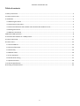
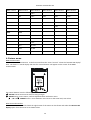
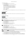
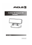
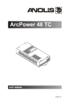
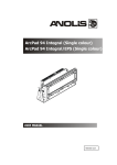
2. Fixture exterior view
Correct interconnection
of LED modules and
control unit has to be
kept . The Chogori
connectors are marked
by self-adhesive labels:
LED1- LED Zone 1
LED2- LED Zone 2
LED3- LED Zone 3
LED4- LED Zone 4
1. PSU
2. Power/data cable
3 Junction box
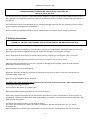
4. LED modules connection cables + Chogori connectors (females):
4
Pin
1
2
3
4
5
6
7
8
LED
RW+
WBB+
GG+
R+
ArcPower 192 Outdoor US
3. Installation
3.1 Mounting the fixture
Ensure that the structure (truss, wall) to which you are attaching
the unit is secure.
Fixture must be installed by a qualified electrician in accordance with all national and local electrical and
construction codes and regulation.
The ArcPower 192 Outdoor US can be arranged in any position orientation.
The housing of the control unit offers two mounting holes, each with a diameter of 13mm .
Caution: Overhead installation requires experience. Fixtures may cause severe injuries when crashing down! If you
have doubts concerning the safety of a possible installation, do not install the device and consult installation with
an expert.
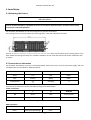
3.2 Connection to the mains
The ArcPower 192 Outdoor US uses a 5-cored power/data cable. The 3 cores serve for the power supply and next
2 shielded cores are intended for DMX connection:
Core
Connection
Core
Connection
Black
Live
Red
Data +
Blue
Neutral
White
Data -
Yellow/Green
GND
PE
Shielding
0
Connect the junction box to mains and DMX acording to the tables below
Power connection
L
N
GND/PE
EU
Braun
Blue
Green/yellow
US
Black
White
Green
This device falls under class one and must be grounded!
DMX connection
+
0
-
Data +
Data ground(shielding)
Data 5
ArcPower 192 Outdoor US
Junction box
ArcPower 192 Outdoor US
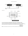
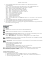
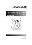
3.3 Connection between LED modules and ArcPower 192 Outdoor US unit
Four pairs of the cable serve for interconnection of the LED modules and the control unit. The Chogori
connectors are marked by self-adhesive labels (LED1, LED2,LED3,LED4) next to the connectors and the following
order of cable connections has to be kept to ensure correct operation of the driver: LED1-LED Zone 1
LED2-LED Zone 2
LED3-LED Zone 3
LED4-LED Zone 4
NOTE: max. length betwen LED module and control unit: 80m (at 350mA load), 20m (at 700mA load).
6
ArcPower 192 Outdoor US
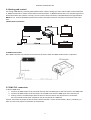
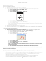
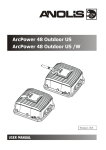
3.4 Setting and control
For setting DMX address, selecting DMX mode and for another settings you need either Robe Universal Interface
or RDM Communicator. Please see the Robe Universal Interface or RDM Communicator user manuals to get more
information about this products. The way, how to connect these interfaces to the DMX data link is figured below.
NOTE: Do not connect the RDM communicator and the The Robe Universal Interface to the fixture at the same
time.
1.Robe Universal Interface
2. RDM Communicator
Note: DMX controller has to be disconnected from the fixture when the RDM communicator is operated.
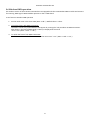
3.5 DMX 512 connection
To build a DMX chain
1. Connect the DMX output of the controller directly with the DMX input of the first fixture in the DMX chain.
2. Connect the DMX output of the first fixture in the DMX chain with the DMX input of the next fixture.
3. Always connect the DMX output with the input of the next fixture until all fixtures are connected.
Do not overload the link. Max. 32 fixtures may be connected on a DMX link.
Caution: Terminate the output of the last fixture with a 120 Ohm resistor wired betwen data (+) and data (-) in
order to ensure the proper transmission on the data link.
7
ArcPower 192 Outdoor US
3.6 Wireless DMX operation
The wireless version of the ArcPower 192 Outdoor US equipped with the Lumen Radio CRMX module and antenna
for receiving DMX signal. CRMX module operates on the 2.4 GHz band.
To set fixture to wireless DMX operation
1. Set the unlink time in the menu PErS (PErS-->rAd.t.). Default value is 1 hour.
2. To link the fixture with DMX transmitter.
The fixture can be only linked with the transmitter by running the link procedure at DMX transmitter .
After linking , the level of DMX signal ( 0-100 %) is displayed in the menu
item “r.InF.“ (SPEC-->rAdI.--> r.InF.)
3. To unlink the fixture from DMX transmitter.
The fixture can be unlinked from receiver via the menu item “ UnL.“ (SPEC-->rAdI.--> UnL.).
8
ArcPower 192 Outdoor US
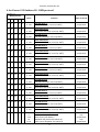
4. ArcPower 192 Outdoor US - DMX protocol
Version 1.0
Mode/channel
Value
1
2
3
4
5
1
1
1
1
1
2
3
4
5
6
7
8
9
-
2
3
4
5
6
7
8
9
2
3
4
5
6
7
8
9
10 10
11 11
12 12
10 13 13
11 14 14
12 15 15
-
16 16
-
17
2
3
1
2
3
1
2
3
1
2
3
-
Function
Type of control
0 - 255
Red LEDs-Zone 1
Red LEDs saturation control (0-100%)
proportional
0 - 255
Green LEDs-Zone 1
Green LEDs saturation control (0-100%)
proportional
0 - 255
Blue LEDs-Zone 1
Blue LEDs saturation control (0-100%)
proportional
0 - 255
White LEDs-Zone 1
White LEDs saturation control (0-100%)
proportional
0 - 255
Red LEDs-Zone 2
Red LEDs saturation control (0-100%)
proportional
0 - 255
Green LEDs-Zone 2
Green LEDs saturation control (0-100%)
proportional
0 - 255
Blue LEDs-Zone 2
Blue LEDs saturation control (0-100%)
proportional
0 - 255
White LEDs-Zone 2
White LEDs saturation control (0-100%)
proportional
0 - 255
Red LEDs-Zone 3
Red LEDs saturation control (0-100%)
proportional
0 - 255
Green LEDs-Zone 3
Green LEDs saturation control (0-100%)
proportional
0 - 255
Blue LEDs-Zone 3
Blue LEDs saturation control (0-100%)
proportional
0 - 255
White LEDs-Zone 3
White LEDs saturation control (0-100%)
proportional
0 - 255
Red LEDs-Zone 4
Red LEDs saturation control (0-100%)
proportional
0 - 255
Green LEDs-Zone 4
Green LEDs saturation control (0-100%)
proportional
0 - 255
Blue LEDs-Zone 4
Blue LEDs saturation control (0-100%)
proportional
0 - 255
White LEDs-Zone 4
White LEDs saturation control (0-100%)
proportional
0
1-15
16
17-55
Virtual colour wheel (all zones)
No function
White tones (coolwarm)
Blue (Blue=full, Red+Green+White=0)
Red=0, Greenup,Blue =full, White=0
step
proportional
step
proportional
2
3
4
1
2
3
4
1
2
3
4
1
2
3
4
-
9
ArcPower 192 Outdoor US
-
-
-
-
18
19
-
4
56
57 - 95
96
97 – 134
135
136 - 174
175
176 -214
215
216 - 254
255
Light Blue (Red=0, Green=full, Blue =full, White=0)
Red=0, Green=full, Bluedown, White=0
Green (Red=0, Green=full, Blue =0, White=0)
Redup, Green=full, Blue=0, White=0
Yellow (Red=full, Green=full, Blue=0, White=0)
Red=full, Greendown, Blue=0, White=0
Red(Red=full, Green=0, Blue=0, White=0)
Red=full, Green=0, Blueup, White=0
Magenta (Red=full, Green=0, Blue=full, White=0)
Reddown, Green=0, Blue=full, White=0
Blue (Red=0, Green=0, Blue=full, White=0)
step
proportional
step
proportional
step
proportional
step
proportional
step
proportional
step
0-31
32-63
64-95
96-127
128-143
144-159
160-191
192-223
224-255
Shutter/ Strobe (all zones)
Shutter closed
Shutter open
Strobe-effect from slow to fast
Shutter open
Opening pulses in sequences slow--> fast
Closing pulses in sequences fast --> slow
Shutter open
Random strobe-effects from slow to fast
Shutter open
step
step
proportional
step
proportional
proportional
step
proportional
step
0 - 255
Dimmer (all zones)
Dimmer intensity from 0% to 100%
proportional
-
5
10
ArcPower 192 Outdoor US
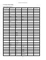
5. Control menu map
Default settings=Bold print
Menu Level 1
Menu Level 2
A001
001-512
InFo
Poti.
Menu Level 3
Menu Level 4
totL
rSEt
DM.In.
rEd1
0-255
:
dimr
tEMP.
0-255
Cur.t.
Hi.tE.
rSEt
VErS.
IC1
IC2
PErS
dM.Pr.
Mod.1
Mod.2
Mod.3
Mod.4
Mod.5
Mod.6
rAd.t.
0.1-25.5
1 (default)
M.F.ti.
0.1-25.5
tEM.U.
°C, °F
bALA
bAL1
On, Off
bAL2
On, Off
bAL3
On, Off
bAL4
On, Off
Stor.
C.bAL.
rEd1
0..200..255
11
Menu Level 5
Menu Level 6
ArcPower 192 Outdoor US
Menu Level 1
Menu Level 2
Menu Level 3
Menu Level 4
GrE1
0..........255
bLu1
0..237..255
:
rEd4
0..200..255
GrE4
0..........255
bLu4
0..237..255
Stor.
LOAd
Out1
0.35A ; 0.70A
Out2
0.35A ; 0.70A
Out3
0.35A ; 0.70A
Out4
0.35A ; 0.70A
Stor.
In.Po.
rEd1
0-255
:
dimr
0-255
Stor.
dFSE
Yes
No
MAn.M.
rEd1
0-255
:
dimr
0-255
Auto
Off
tESt
St.AL.
tESt
PrG.1
PrG.2
PLAY
tESt
PrG.1
12
Menu Level 5
Menu Level 6
ArcPower 192 Outdoor US
Menu Level 1
Menu Level 2
Menu Level 3
Menu Level 4
Menu Level 5
Menu Level 6
PrG.1
St.01
rEd1
0-255
:
:
:
:
PrG.2
St.68
S.tim.
0-25.5 sec
PrG.2
Edit
CoPY
SPEC.
rdML
rdMH
rAdI
r.InF.
r.UnL.
I.bLi
On, Off
Hold
On,Off
uPd.
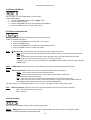
6. Fixture menu
RDM communicator:
Connect the RDM communicator to the fixture and from the menu “Control” select the “Remote LED display”
item. The fixture´s control display with the four control buttons will appear on the screen of the RDM
communicator.
The control buttons have the following functions:
- ESCAPE button-leaves menu without saving changes.
- ENTER button- enters menu, confirms adjusted values and leaves menu.
- UP and - DOWN buttons - move between menu items on the same level, sets values.
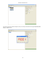
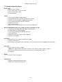
Robe Universal Interface:
Run the RDM-network and click with the right button of the mouse on the fixture and select the Remote LED
display option from the menu list as shown below.
13
ArcPower 192 Outdoor US
The Remote LED Display window will appear. Now you can fullly control the fixture using the UP, Down, Enter,
Escape and Reset buttons.
14
ArcPower 192 Outdoor US
6.1 Fixture Address
Use this menu to set the DMX address of the fixture.
To set a DMX address.
1. Use the UP/DOWN buttons to find “ A001“ menu.
2. Press the ENTER button.
3. Use the UP/DOWN buttons to select desired start address.
4. Press the ENTER button to confirm the choice.
6.2 Fixture information
Use this menu to read useful information about the fixture status.
To display desired information.
1. Use the UP/DOWN buttons to find the “ InFo“ menu.
2. Press the ENTER button.
3. Use the UP/DOWN buttons to select the required menu item.
4. Press the ENTER button to confirm the choice.
Po.ti. --- Power On Time. Use the menu item to read the number of operation hours.
totL - the function shows the total number of the operation hours since the PSU Xtreme has been
fabricated.
rESEt - the function shows the number of the operation hours that the PSU Xtreme has been
powered on since the counter was last reset. In order to reset this
counter to 0 you have to press and hold the UP and DOWN buttons and at the same time press the
ENTER button.
DM.In.--- DMX values. Select this function to read DMX values of each channel received by the fixture.
tEMP --- Fixture Temperatures. Select this menu to read the temperatures of the fixture:
Cur.t. --- the current temperature of the fixture inside.
Hi.tE. - the menu item shows the max. temperatures of the fixture inside since
the PSU Xtreme has been fabricated.
rSEt --- the menu item shows the maximum temperatures of the fixture inside since
the counter was last reset. In order to reset this counter to 0 you have to press and hold the UP
and DOWN buttons and at the same time press the ENTER button.
The temperatures can be displayed either in °C or °F units - see option “tEM.U“ in the menu “Pers“
VErS. ---Software Versions. Select this function to read the software versions of the fixture processors.
IC1 --- LED modules control processor
IC2 --- EEprom
6.3 Personality
Use this menu to modify the PSU Xtreme operating behaviour.
DM.Pr. --- DMX preset. Select this menu item to set a desired DMX mode. Please refer to the chapter "DMX
protocol" for detail description of each DMX mode.
15
ArcPower 192 Outdoor US
rAd.t. --- Unlink time. Use this menu to set time after that the linked fixture will be unliked from the transmitter, if
the transmitter does not transmit DMX signal.
OFF --- Fixture is permanently linked to the transmitter.
0.1-25.5 --- Time from 0.1-25.5 hrs. Default value is 1 hr.
M.F.ti. --- Max. Fade time. Select this menu item to set a desired max. fade time (0-25.5 sec.). This adjusted fade
time influences fade of RGB and dimmer during DMX operation:
If time between two receiving DMX values is > than fade time set in the item M.F.ti., the entire adjusted fade time
will be used.
If time between two receiving DMX values is < than fade time set in the item M.F.ti., the adjusted fade time will be
reduced to fill entire time between the two receiving DMX values.
e.g. M.F.ti.=2sec. and fixture has received Red=0 DMX, after 5 seconds will receive Red=255 DMX. It means, that
red will go to full intensity during 2 seconds.
M.F.ti.=8 sec. and fixture has received Red=0 DMX, after 5 seconds will receive Red=255 DMX. It means, that red
will go to full intensity during 5 seconds. (Max, fade time is reduced from 8 sec. to 5 sec.).
tEM.U. --- Temperature Unit. Use this menu in order to display the fixture temperatures in desired units: °C or °F.
bALA --- White colour balance Use this menu item to enable (On) or disable (Off) the white balance which is set in
the “White colour balance“ menu below. I f this function is set off, the will use maximum value (255) of saturation
for red, green and blue colour. This function has to be set on before adjusting a white balance. The white colour
balance can be switched on/off for each LED output independent.
C.bAL. --- White colour balance setting. The menu gives access to the setting of the white balance.
The white colour balance can be set for each LED output independent.
To set the white colour balance.
1. Use a DMX controller or the “ Man.C.“ menu to set all LEDs on max. saturation.
2. Use the UP/DOWN buttons to find the “ Pers.“ menu.
3. Press the ENTER button.
4. Use the UP/DOWN buttons to select the “C.bAL“menu.
5. Press the ENTER button and the “rEd1“ item will appear on the display.
6. Press the ENTER button and use the UP/DOWN buttons to set new max. value for the red LEDs.
7. Press the ENTER button to confirm the choice.
8. Use the UP/DOWN buttons to select next colour, the “GrE1“.
9. Repeat steps 6-7 for this channel.
10. Use the UP/DOWN buttons to select the last colour, the „bLu1“ and repeat steps 6-7 for this colour.
11. Repeat this procedure for all LED outputs
12. Use the UP/DOWN buttons to find the item “ Stor.“ and press the ENTER button to save adjusted values.
LoAd --- Load of LED outputs. The menu allows to choose desired current (350mA or 700mA) for each LED output.
Warning: Set the “Load“ item before connecting the LED modules to the driver.
Never connect 1Watt LEDs to the 700mA output otherwise these LEDs vill be destroyed.
In.Po. --- Init effect positions. Use this function to set all effects to the desired positions to which they will move
after switching the fixture on (if DMX is not being received).
dF.SE. --- Default Settings .The menu item sets all fixture parameters to the default (factory) values.
6.4 Manual mode
Use this menu for control the fixture without connected DMX console.
16
ArcPower 192 Outdoor US
To control fixture channels.
1. Use the UP/DOWN buttons to find “ Man.M“ menu.
2. Press the ENTER button.
3. Use the UP/DOWN buttons to select desired effect (channel).
List of control channels:
“rEd1” - “rEd4” - red LEDs saturations, LED modules 1 -4
“GrE1“ - “GrE4“ - green LEDs saturations, LED modules 1 -4
“bLu1“ - “bLu4“ - blue LEDs saturations, LED modules 1 -4
“Whi1“ - “Whi4“ white LEDs saturations, LED modules 1-4
“MACr“ - colour macros
“Stro.“ - a strobe, shutter
“dimr“ - a dimmer
4. Press the ENTER button and use the UP/DOWN buttons to set value , press the ENTER button to confirm it.
6. 5 Test sequences
Use this menu to run test sequences without an external controller, which will show you some possibilities of
using the PSU Xtreme.
6.6 Stand-alone setting
The fixtures on a data link are not connected to the controller but can execute pre-set programs which can be
different for every fixture.
Auto. --- Automatic playback. This function allows you to select the program which will be played after switching
the fixture on. Selected program will be played continuously in a loop.
1. Use the UP/DOWN buttons to find “ St.AL.“ menu.
2. Press the ENTER button.
3. Use the UP/DOWN buttons to select “ Auto“ item.
4. Press the ENTER button.
5. Use the UP/DOWN buttons to select desired program.
6. Press the ENTER button to confirm the choice.
PLAY --- Playing program. By enter to this menu a complete overview of all programs is offered, from which the
program to be run can be selected.
1. Use the UP/DOWN buttons to find “ St.AL.“ menu.
2. Press the ENTER button.
3. Use the UP/DOWN buttons to select desired program.
4. Press the ENTER button. The selected program runs in a loop.
Edit --- Editing a program. The fixture offers 2 freely editable programs (PrG.1,PrG.2) each up to 68 steps. Every
program step includes a fade time-the time taken by the step´s channel status to reach the desired level and a
step time-the total time occupied by the step in the program.
E.g. If “F.tim.“=5 second and “S.tim.“=20 second, effects will go to the desired position during 5 seconds and after
that they will stay in this position for 15 seconds before going to the next prog. step
1. 1. Use the UP/DOWN buttons to find “ St.AL.“ menu and press the ENTER button.
2. Use the UP/DOWN buttons to select “Edit“ menu and press the ENTER button.
3. Use the UP/DOWN buttons to select a program you want to edit (PrG.1,PrG.2 and press ENTER button.
4. Use the UP/DOWN buttons to select a desired program step ("St.01" - "St.68") and press ENTER button.
17
ArcPower 192 Outdoor US
5. Use the UP/DOWN buttons to select a channel you want to edit and press the ENTER button.
List of editable items:
“P.End” - a total number of the program steps (value 1-68). This value should be set before start
programming (e.g. if you want to create program with 10 steps, set P.End=10).
“rEd1” - “rEd4” – a red LEDs saturation(0-255), module 1-4
“GrE1“ - “GrE4“ –a green LEDs saturation (0-255) ), module 1-4
“bLu1“ - “bLu4“ – a blue LEDs saturation (0-255) ), module 1-4
“Whi1“ - “Whi4“ – a white LEDs saturation (0-255) ), module 1-4
“MACr“ - colour macros (0-255), both modules
“Stro.“ - a strobe, shutter (0-255), both modules
“dimr“ - a dimmer (0-255), both modules
“F.tim.“ - a fade time, (0-25.5) seconds
“S.tim.“ - step time, value (0-25.5) seconds
“COPY“. – this item duplicates the current prog. step to the next prog. step. The item “P.End” is increased
automatically.
6. Use the UP/DOWN buttons to set a DMX value of the channel and then press the ENTER button.
7. Use the UP/DOWN buttons to select next channel and press the ENTER button.
8. After having set all channels in the current program step, press the ESCAPE button to go by one menu level
back and select another program step.
6.7 Special functions
rdML --- Code.This menu item shows the first part of the RDM identification code.
rdMH --- Code. This menu item shows the second part of the RDM identification code.
rAdI --- Wireless DMX (only wireless DMX version). The menu serves for reading of the wireless operation status.
r.InF. --- Signal level. The menu item shows level of received signal in %.
r.UnL. --- Wireless DMX unlink. The item serves for unlinking the fixture from a DMX transmitter.
HoLd --- Holding DMX. If the function is on, the last received DMX values are held in case, that DMX data receiving
was interrupted (e.g. disconnected DMX controller).
uPd.M. --- Updating mode. The menu item allows you to update software in the fixture via either serial or USB port
of PC.
The following are required in order to update software:
- PC running Windows 95/98/2000/XP or Linux
- DMX Software Uploader
- Flash cable RS232/DMX No.13050624 (if you want to use a serial port of PC)
- Robe Universal Interface (if you want to use an USB port of PC)
Note1: Software update should execute a qualified person. If you lack qualification, do not attempt the update
yourself and ask for help your ROBE distributor.
Note 2: DMX address, programs 1,2 and all items in the menu "PErS" will be set to their default values.
To update software in the fixture:
I. Installation of the DMX Software Uploader.
1. DMX Software Uploader program is available from theAnolis web site at WWW.anolis.cz.
2. Make a new directory ( e.g. Anolis_Uploader) on your hard disk and download the software into it.
3. Unpack the program from the archive.
18
ArcPower 192 Outdoor US
II.Fixture software updating.
If you use the RDM Communicator:
1. Disconnect the fixture from other fixtures in a DMX link.
2. Connect the RDM communicator to the fixture and switch this fixture to the update mode :
1 Use the UP/DOWN buttons to find “SPEC.“ menu.
2 Press the ENTER button.
3 Use the UP/DOWN buttons to select “ uPd.“ item.
4 Press the ENTER button
5 Use the UP/DOWN buttons to select “ yES“ option
6 Press the ENTER button
Note: If you do not want to continue in software update, you have to switch off and on the fixture
to escape from this menu.
3. Disconnect the RDM communicator from the fixture.
4. Connect serial port of your PC with a DMX input of the fixture if you using the flash cable RS232/DMX.
If you use the Robe Universal Interface:
1. Disconnect the fixture from other fixtures in a DMX link.
2. Connect the Robe Universal Interface to the fixture and switch this fixture to the update mode :
1. Run the RDM-Network and select menu item “Remote LED Display”
2. Use the UP/DOWN buttons to find “SPEC.“ menu.
3. Press the ENTER button.
4. Use the UP/DOWN buttons to select “ uPd.“ item.
5. Press the ENTER button
6. Use the UP/DOWN buttons to select “ yES“ option
7. Press the ENTER button
Note: If you do not want to continue in software update, you have to switch off and on the fixture
to escape from this menu.
8. After switching the fixture to the update mode cancel the RDM-Network program.
Run the Software Uploader program. Select desired COM (select Robe Universal Interface if the USB port is used)
and then click on the Connect button.
Note: we recommend to cancel all running programs before starting the Software Uploader.
If the connection is OK, click on the Start Uploading button to start uploading. It will take everal minutes to
perform software update. If the option "Incremental Update" is not checked, all processors will be
updated (including processors with the same software version).
If you wish to update only the latest versions of processors, check the Incremental Update box.
Avoid interrupting the process. Update status is being displayed in the Info Box window.
19
ArcPower 192 Outdoor US
When the update is finished, the line with the text “The fixture is successfully updated‘will appear in this
window and the fixture will reset with the new software.
20
ArcPower 192 Outdoor US
7. Technical specifications
Power supply
• Electronic auto-ranging
• Input voltage: 100 - 277V AC, 50-60 Hz
• Power consumption: 600W
• Fuse: F12A/250V
Control
• Control: USITT DMX 512 (RDM support)
• DMX protocol modes: 5 (12,16,19,4,5) control channels
• Manual control of all effects via RDM communicator
• 2 user editable programs each up to 68 steps
• RGBW colour mixing
• Built-in colour macros
• White colour balance adjusting for each LED output separately
Wireless DMX/RDM module (only for Robin ArcPower 192 Outdoor US /W)
• Compliance with USITT DMX-512 (1986 & 1990) and 512-A
• Full DMX fidelity and frame integrity
• Auto sensing of DMX frame rate and frame size
• <5ms DMX latency
• Operational frequency range of 2402-2480 MHz
• Producer: LumenRadio
LED output
• Max.Output current: 350mA or 700 mA per colour
• Number of LED zones: 4
• Max. load per zone: 48LEDs (1W or 3W LEDs, max. 12 LEDs per colour) or 12 RGBW multichips (10W)
Connection
• LED modules connectors: Chogori
NOTE: max. length betwen LED module and control unit: 80m (at 350mA), 20m (at 700mA)
• Connection between control unit and junction box: 5-cored power/data cable
• junction box
Rigging
• Via slots in base of the driver
Temperatures
• Maximum ambient temperature: 40° C
• Maximum housing temperature: 60° C
21
ArcPower 192 Outdoor US
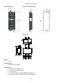
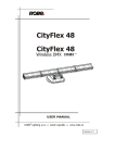
Dimensions (mm)
ArcPower 192 Outdoor US
Junction box
Weight
• 9 kg
Protection factor
• Suitable for wet location
Included items
• 1 x ArcPower 192 Outdoor US
• 1 x Junction box (P/N9971 4886)
• 1 x User manual
• 4 x Connector Chogori CGRBDU 08BMMA-SL8001(male)
• 1 x Gasket of cable grommet M20, PF ½ (P/N 1305 1388)
22
ArcPower 192 Outdoor US
8. Cleaning and maintenance
DANGER !
Disconnect from the mains before starting any cleaning or maintenance work
Rinse off loose dirt with a garden hose or low pressure water spray. Wash the housing with a soft brush or sponge
and a mild, non-abrasive washing detergent. Rinse it.
There are no serviceable parts inside the device.
Maintenance and service operations are only to be carried out by a qualified person.
Should you need any spare parts, please use genuine parts.
If the power supply cable of this device will be damaged (cable firmly connected with the device), it has to be
replaced by authorized distributors only in order to avoid hazards.
Specifications are subject to change without notice.
November 23, 2015
23