1
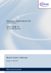
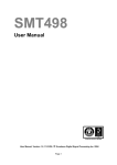
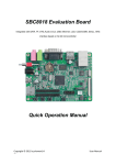
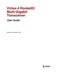
Sundance Multiprocessor Technology Limited
User Manual
Unit / Module Description:
What is this all about?
Unit / Module Number:
SMT362
Document Issue Number:
2.2
Issue Date:
29th April 2009
Original Author:
Graeme Parker
Form : QCF42
Date : 6 July 2006
User Manual
for
SMT362
Sundance Multiprocessor Technology Ltd, Chiltern House,
Waterside, Chesham, Bucks. HP5 1PS.
This document is the property of Sundance and may not be copied
nor communicated to a third party without prior written
permission.
© Sundance Multiprocessor Technology Limited 2006
User Manual SMT362
Last Edited: 29/04/2009 08:56
Revision History
Issue
Changes Made
Date
Initials
1.0
First release.
5/2/07
GKP
1.1
Update
20/6/07
GKP
Added CCS basic info.
2/8/07
GKP
1.2
Added default firmware links configuration
2/6/08
E.P
1.3
Added McBSP connectivity detail.
21/7/08
GKP
1.4
Added FPGA pin-out
22/7/08
GKP
2.0
Major update to include missing detail from the
technical specification.
3/10/08
GKP
2.1
Corrected PHY references.
17/12/08
GKP
2.2
Default for McBSP1 or GPIO is GPIO.
29/4/09
GKP
1.1.1
User Manual SMT362
Page 2 of 30
Last Edited: 29/04/2009 08:56
Table of Contents
1
Introduction.....................................................................................................................4
2
Related Documents ........................................................................................................5
3
Acronyms, Abbreviations and Definitions ...................................................................5
4
Functional Description...................................................................................................6
4.1
Block Diagram ............................................................................................................6
4.2
Module Description.....................................................................................................7
4.2.1 Mechanical Interface..............................................................................................7
4.2.2 Processor...............................................................................................................7
4.2.3 Flash ......................................................................................................................7
4.2.4 DSP Reset .............................................................................................................7
4.2.5 DSP Boot ...............................................................................................................9
4.2.6 Host Port Interface (HPI) .......................................................................................9
4.2.7 Virtex 4 FX FPGA ................................................................................................10
4.2.8 GPIO (General Purpose I/O) ...............................................................................13
4.2.9 LEDs ....................................................................................................................14
4.2.10 Ethernet ...............................................................................................................15
4.2.11 RapidIO and RSLs...............................................................................................17
4.2.12 McBSP & Timers .................................................................................................18
4.2.13 Power Supplies....................................................................................................18
5
Footprint........................................................................................................................19
5.1
Top View ..................................................................................................................19
5.2
Bottom View .............................................................................................................20
6
Support Packages ........................................................................................................21
6.1
Code Composer Studio ............................................................................................21
6.2
3L Diamond ..............................................................................................................21
7
Physical Properties ......................................................................................................22
8
FPGA Pin-out (ucf) .......................................................................................................23
9
Safety.............................................................................................................................30
10
EMC ..............................................................................................................................30
User Manual SMT362
Page 3 of 30
Last Edited: 29/04/2009 08:56
1
Introduction
The SMT362 is a dual processor module. Each TMS320C6455 processor runs at up to
1GHz. This provides a module performance of up to 16GIPS.
Each processor has independent access to 256Mbytes of DDR2 memory.
A single 4Mbyte flash memory device is directly connected to the primary DSP (DSP A). This
device contains the DSP boot code and FPGA (Virtex-4) configuration.
The secondary DSP (DSP B) boots from its Host Port Interface, which is directly connected
to DSP A.
The FPGA provides 6 TIM compatible comm. ports, 2 Sundance SHBs, up to 16 RSLs, and
other minor functions. The FPGA can be easily customised.
The SMT362 could be used in applications where the FPGA does the pre-processing, the
first DSP the ‘Input Signal Processing’, the second DSP does ‘Output Signal Processing’,
and the FPGA does the final post-processing.
User Manual SMT362
Page 4 of 30
Last Edited: 29/04/2009 08:56
2
Related Documents
TI TMS320C6455 material (http://focus.ti.com/docs/prod/folders/print/tms320c6455.html).
Sundance SHB specification. (ftp://ftp2.sundance.com/Pub/documentation/pdffiles/SHB_Technical_Specification_v1_0.pdf)
Sundance RSL specification. (http://www.sundance.com/docs/RSL - Technical Specification
Rev01 Iss03.pdf)
TI TIM specification & user’s guide. (ftp://ftp2.sundance.com/Pub/documentation/pdffiles/tim_spec_v1.01.pdf)
3
Acronyms, Abbreviations and Definitions
A list of acronyms etc (http://www.sundance.com/web/files/static.asp?pagename=acc).
User Manual SMT362
Last Edited: 29/04/2009 08:56
User Manual SMT362
Bottom TIM Connector
ComPorts 1, 2, 4 & 5
Host Port - 16-bit
Page 6 of 30
4xLED
32-bit
256M bytes DDR2
2x (64Mx16)
Block Diagram
C6455 1GHz
DSP B
2xLED
C6455 1GHz
DSP A
2xLED
4.1
EMIF
64-bit
256M bytes DDR2
2x (64Mx16)
Functional Description
4x LVTTL I/O Pins
McBSP
McBSP
8-bit data
JTAG Header
FPGA
Virtex4 XC4VFX60
FF1152 package
1.2V core
EMIF
64-bit
4M bytes
flash
32-bit
2x SHB
Connectors
3x RSL
Connectors
12 lanes
Top TIM Connector
ComPorts 0 & 3
4
Last Edited: 29/04/2009 08:56
4.2
4.2.1
Module Description
Mechanical Interface
This module conforms to the TIM standard for single width modules. It requires an additional
3.3V power supply (as present on all Sundance TIM carrier boards) that must be provided by
the two diagonally opposite mounting holes.
4.2.2
Processor
The module incorporates two TMS320C6455 DSPs.
A JTAG interface is provided to enable application debugging via a suitable JTAG controller
and software. The DSPs’ JTAG interfaces are chained and available only on the Top TIM
connector. Typically, the JTAG controller this will be an SMT107 or 310/Q and TI Code
Composer Studio. This is an invaluable interface that enables the application programmer to
quickly debug a ‘chain’ of processors in single or multi-processor situations.
The DSPs have two external memory interfaces. One connects directly to the DDR2 (2
devices of 128M bytes clocked at 250MHz:DDR2-500) and the other (EMIFA, clocked at
133MHz) is used to interface to the remaining peripherals.
Each DSP provides 4 chip selects (numbered 2-5) on its EMIFA interface. The function of
each is shown below;
Chip
select
Base Address
DSPA
DSPB
CE2
A0000000
FPGA
FPGA
CE3
B0000000
Flash
Unused
CE4
C0000000
HPI of DSPB
Unused
CE5
D0000000
FPGA configuration
Unused
(hex)
Separate to the EMIFA, the DSP provides an interface solely for the connection of DDR2
memory. This is addressed as shown here;
DDR2
4.2.3
E0000000
DDR2 SDRAM
DDR2 SDRAM
Flash
A 4Mbyte flash memory is provided with direct access by DSP A. This device contains boot
code for the DSP and the configuration data for the FPGA.
This device is directly connected to DSP A. This is an 8-bit wide device.
The flash is mapped with address bits 0 & 1 (byte addressing) connected to the top address
of the flash so a sector erase will need to erase 4 sectors at once. This is equivalent to
having a flash of 32 128Kwords sectors (instead of 128 32Kwords sectors). The flash is only
accessible byte-wise so it gives a total capacity of the flash of 4MB.
4.2.4
DSP Reset
The DSPs’ configuration is determined during the reset process. The state of the EMIF
address lines is examined, and this determines the on-chip peripheral status.
User Manual SMT362
Page 7 of 30
Last Edited: 29/04/2009 08:56
The following table details this;
EMIF
A
Comment
EMIF
A
Comment
0
Latched at reset. Not used on
the 362.
10
Pull-up with 1k0. Used to select
MAC with an RGMII interface.
1
Latched at reset. Not used on
the 362.
11
Pull-up via 1k0.
2
Latched at reset. Not used on
the 362.
12
UTOPIA
Internal
EMAC.
3
Pull-up via 1k0.
13
Internal pull-up selects
endian operation.
4
GP01 function. Connected to
CPLD via 1k0. A ‘0’ (default)
makes this an I/O pin. A ‘1’
enables the SYSCLK3 signal to
be output.
14
Internal pull-down selects 16 bit
HPI operation.
5
McBSP1 or GPIO selection.
Connected to the CPLD via 1k0.
A ‘1’ enables the McBSP
(default if GPIO).
15
Connected to CPLD via 1k0. A
‘0’ selects external clock for
EMIF. A ‘1’ selects SYSCLK3/8
as EMIF clock.
6
NC – PCI speed.
16
Internal pull-down. Set to ‘0’ for
DSPA. Set to ‘1’ for DSPB.
Together with EMIFA17-19, this
sets the boot mode.
7
NC – internal pull-down.
17
Internal pull-down.
8
NC – PCI auto-init.
18
Internal pull-down. Set to ‘1’ for
DSPA. Set to ‘0’ for DSPB.
9
Pull-up with 1k0. Used to select
MAC with an RGMII interface.
19
Internal pull-down.
or EMAC
pull-down
select.
selects
little
Boot mode is the 4-bit value from EMIFA[19:16]. This is 0100 for DSPA (ROM boot) and
0001 for DSPB (HPI boot).
User Manual SMT362
Page 8 of 30
Last Edited: 29/04/2009 08:56
4.2.5
DSP Boot
When the module is reset, both DSPs come out of their reset state. DSPA will begin
execution of code stored in the flash memory. DSPB is set to boot from host port, and will
thus wait until is has had its boot code loaded by DSPA. The DSPA boot code (factory
programmed by default) will load the FPGA configuration (again from flash), boot DSPB over
the EMIF to host port interface, perform any necessary initialisation and then enter a
ComPort boot sequence. The ComPort boot involves polling the ComPort status register(s)
and downloading code from the first active port.
DSPB, when booted, will simply enter the ComPort boot sequence after initialising any of its
internal devices.
4.2.6
Host Port Interface (HPI)
The HPI of DSPA is not connected, and DSPB’s is connected to the EMIF of DSPA.
User Manual SMT362
Page 9 of 30
Last Edited: 29/04/2009 08:56
4.2.7
Virtex 4 FX FPGA
This device, a Xilinx XC4VFX, is responsible for the provision of the two SHBs, 6 Com-Ports,
and the RSLs. On power-up, this device is un-configured (SRAM based FPGA technology).
During the DSP boot process, the FPGA is configured for normal operation.
4.2.7.1 FPGA Configuration
Before any functions of the FPGA can be used it must be configured. This is a
process undertaken by DSP A during its boot procedure. The FPGA is configured via
the slave serial mode with the DSP presenting the serial data on EMIF data bit 8.
First, the PROG pin must be asserted low, then high. The FPGA’s PROG pin is
connected directly to DSPA’s general purpose i/o pin 2 (GPIO).
Then data must be read from the flash (During the normal boot process, the
configuration data is read from flash. If the FPGA needs to be reconfigured during
application execution, then the configuration data maybe read from any source.) and
written to the FPGA.
This procedure is completely automatic during the module’s boot process.
Removing jumper JP2 will hold the FPGA in an unconfigured state. This could be
useful if an erroneous bit stream has been loaded into flash (EMIF data bus
corruption etc), which could result in the module not being accessible even using
Code Composer (JTAG).
4.2.7.2 FPGA Configuration via JTAG
The FPGA may also be configured using a Xilinx JTAG programming system
connected to header JP1. The pin-out of this header is given here;
User Manual SMT362
Signal
Pin
Pin
Signal
Power
1
4
TMS
Ground
2
5
TDI
TCK
3
6
TDO
Page 10 of 30
Last Edited: 29/04/2009 08:56
4.2.7.3 Com-Ports
Figure 1: Default firmware ComPort links..
4.2.7.4 SHB
The SMT362 has two SHB connectors, both of which are connected to DSPA to give
32-bit SDB interfaces.
SDB0 and SDB1 on DSPA are presented on the TIM's SHB connectors, SHBA and
SHBB respectively. SDB0 and SDB1 on DSP-B are not connected. SDB2 of DSPA
has a fixed internal connection to SDB2 of DSPB.
Figure 2: Default firmware SHB links. See the general firmware description.
User Manual SMT362
Page 11 of 30
Last Edited: 29/04/2009 08:56
4.2.7.5 PXI
An external PXI clock and 4 trigger signals are available on the user defined pins of
the TIM connectors. These can be used for a variety of purposes, including
synchronisation and triggering of data acquisitions, or for any user application specific
function.
User Manual SMT362
Page 12 of 30
Last Edited: 29/04/2009 08:56
4.2.8
GPIO (General Purpose I/O)
Two GPIO signals from each DSP are used to illuminate LEDs as shown here;
DSPA
DSPB
GPIO 14
D3
D5
GPIO 15
D2
D4
The LEDs are labelled on the board as ‘Dn’.
Four other GPIO signals from the FPGA are connected directly (un-buffered, 3.3V LVTTL
ONLY) to connector JP3. The pin-out and FPGA pad number is shown here;
Signal
Pin
Pin
Signal
3.3V
1
4
Pad D10
Ground
2
5
Pad H10
Pad C10
3
6
Pad G10
All of the DSP’s GPIO signals are described here;
GPIO
0
1
2
3
4
5
6
7
Function
GPIO
CLKR1 (to FPGA)
SYSCLK3
PROG
CLKX1 (to FPGA)
INT4 (to FPGA)
INT5 (to FPGA)
INT6 (to FPGA)
INT7 (to FPGA)
8
9
10
11
12
13
14
15
Function
DR1 (to FPGA)
DX1 (to FPGA)
FSR1 (to FPGA)
FSX1 (to FPGA)
Flash A20
Flash A21
LED1
LED2
The McBSP signals (CLKR1, CLKX1, DR1, DX1, FSR1 and FSX1) are all connected to the
FPGA. They are normally set to function as McBSP signals, but it is possible to enable these
as GPIO and hence a source of a further 6 interrupts to the DSP.
The above signals are independent between DSPs.
GPIO2, 12 and 13 are connected to the FPGA on DSPB (DSPB does not have access to a
flash memory and cannot configure the FPGA).
User Manual SMT362
Page 13 of 30
Last Edited: 29/04/2009 08:56
4.2.9
LEDs
Eleven LEDs are present on the SMT362. Their function and position are shown here;
LED
User Manual SMT362
Function
D1
FPGA DONE status
(illuminates when the
FPGA is configured)
D2
DSPA GP15
D3
DSPB GP14
D4
DSPB GP15
D5
DSPB GP14
D6
PHY LED0
D7
PHY LED1
D9
FPGA pad J9
D10
FPGA pad H9
D11
FPGA pad F9
D12
FPGA pad F10
Page 14 of 30
Last Edited: 29/04/2009 08:56
4.2.10 Ethernet
A Marvell 88E1116 PHY is connected to a 1.8V I/O bank of the FPGA. Each of the DSP
Ethernet PHY interfaces are also connected to the FPGA. This connectivity should allow
routing of data from either DSP to the RJ45 connector (optional).
On the SMT362 PCB, pin headers are provided to connect into the Ethernet system. We
recommend the use of the Halo HFJ11-1G01E ‘Fastjack’ connector.
Sundance can supply the SMT562E PC rear panel which includes the RJ45 connector and a
connecting cable (see picture on following page).
For non-gigabit applications, a twisted pair wired connection can be made from the RJ1
connector pins to a suitable panel mount socket.
User Manual SMT362
Page 15 of 30
Last Edited: 29/04/2009 08:56
SMT362 connected to the SMT562E for Gigabit Ethernet applications. Note the polarity of
each end of the cable.
Virtex 4FX
MAC
DSPA
M
A
C
MAC
MAC
MAC
LVTTL33
GMII
LVCMOS25
GMII
HSTL15
RGMII
LVCMOS25
RGMII
DSPB
M
A
C
Marvell
88E1111
LVTTL33
GMII
HSTL15
RGMII
The default configuration of connecting DSPB’s MAC directly to the 88E1116 PHY
through the Virtex 4 is shown in the diagram above. In this configuration, the Virtex 4
is essentially acting as a voltage translator.
User Manual SMT362
Page 16 of 30
Last Edited: 29/04/2009 08:56
4.2.11 RapidIO and RSLs
The FPGA provides 16 RocketIO serial interfaces. These are normally run at 2.5Gbps.
Each DSP has 4 SRIO interfaces. Again, these are normally run at 2.5Gbps.
All of these serial interfaces are knows in Sundance as RSL (Rocket Serial Link).
The RSL connectivity is shown here;
RSLA
Bottom
4 RSL
4 RSL
RSLB
Bottom
Virtex 4 FX
FPGA
RSLA
Top
4 RSL
2 RSL
DSPA
User Manual SMT362
2 RSL
2 RSL
Page 17 of 30
DSPB
Last Edited: 29/04/2009 08:56
4.2.12 McBSP & Timers
Each DSP has two McBSPs (multi-channel buffered serial port), 0 and 1.
McBSP1 from DSPA connected to McBSP1 on DSPB.
McBSP0 from each DSP is connected independently to the FPGA.
The full FPGA pin-out is given in the smt362_fpga_pinout.ucf file.
The following link covers the McBSP operation in detail:
http://focus.ti.com/lit/ug/spru580g/spru580g.pdf
Each DSP has two timers composed from two pins, TINP and TOUTP. All four of these pins
(for each DSP) are connected to the FPGA.
4.2.13 Power Supplies
This module must have 5V supplied through the TIM connectors. In addition, a 3.3V supply is
required and should be supplied through the TIM mounting holes. This is compatible with the
all Sundance TIM carrier boards.
Contained on the module are switching regulators for the ‘C6455s, DDR2 and FPGA.
The RocketIO voltage is provided through a linear regulator from 3.3V.
All supplies a guaranteed to meet the worst possible requirements of the FPGAs.
User Manual SMT362
Page 18 of 30
Last Edited: 29/04/2009 08:56
5
Footprint
5.1
Top View
User Manual SMT362
Last Edited: 29/04/2009 08:56
5.2
Bottom View
User Manual SMT362
Page 20 of 30
Last Edited: 29/04/2009 08:56
6
Support Packages
6.1
Code Composer Studio
The C6455 is supported under Texas Instrument’s Code Composer Studio
(http://focus.ti.com/dsp/docs/dspsupporto.tsp?sectionId=3&tabId=453) development tools.
For a single SMT362 system, the Code Composer Setup should show a system similar to
this;
Both Subpath ports should be set to the value 0x10.
6.2
3L Diamond
A Diamond processor type is defined. Please consult the relevant 3L documentation.
User Manual SMT362
Last Edited: 29/04/2009 08:56
7
Physical Properties
Dimensions
4.2”
2.5”
Weight
Supply Voltages
+5, +3.3V
Supply Current
+12V
0
+5V
+3.3V
-5V
0
-12V
0
MTBF
User Manual SMT362
Last Edited: 29/04/2009 08:56
8
FPGA Pin-out (ucf)
BOARDCLK
AG17
DSPB_EMIF_DATA<21>
AM8
CP0_DATA<0>
W6
DSPB_EMIF_DATA<22>
AB12
CP0_DATA<1>
W7
DSPB_EMIF_DATA<23>
AC12
CP0_DATA<2>
AA4
DSPB_EMIF_DATA<24>
AH7
CP0_DATA<3>
AA5
DSPB_EMIF_DATA<25>
AH8
CP0_DATA<4>
V7
DSPB_EMIF_DATA<26>
AA13
CP0_DATA<5>
V8
DSPB_EMIF_DATA<27>
AB13
CP0_DATA<6>
W4
DSPB_EMIF_DATA<28>
AJ7
CP0_DATA<7>
W5
DSPB_EMIF_DATA<29>
AK7
CP0_RDY
Y4
DSPB_EMIF_DATA<30>
AA11
CP0_REQ
Y7
DSPB_EMIF_DATA<31>
AB11
CP0_ACK
Y3
DSPB_EMIF_DATA<32>
AG5
CP0_STB
Y8
DSPB_EMIF_DATA<33>
AG6
CP1_DATA<0>
K8
DSPB_EMIF_DATA<34>
AL6
CP1_DATA<1>
K9
DSPB_EMIF_DATA<35>
AM6
CP1_DATA<2>
E12
DSPB_EMIF_DATA<36>
AD6
CP1_DATA<3>
E13
DSPB_EMIF_DATA<37>
AD7
CP1_DATA<4>
E6
DSPB_EMIF_DATA<38>
AG7
CP1_DATA<5>
E7
DSPB_EMIF_DATA<39>
AG8
CP1_DATA<6>
H12
DSPB_EMIF_DATA<40>
AL3
CP1_DATA<7>
J12
DSPB_EMIF_DATA<41>
AM3
CP1_RDY
H7
DSPB_EMIF_DATA<42>
AJ6
CP1_REQ
G7
DSPB_EMIF_DATA<43>
AK6
CP1_ACK
K11
DSPB_EMIF_DATA<44>
AH3
CP1_STB
L11
DSPB_EMIF_DATA<45>
AH4
CP2_DATA<0>
K7
DSPB_EMIF_DATA<46>
AE7
CP2_DATA<1>
J7
DSPB_EMIF_DATA<47>
AF8
CP2_DATA<2>
G11
DSPB_EMIF_DATA<48>
AF4
CP2_DATA<3>
G12
DSPB_EMIF_DATA<49>
AF5
CP2_DATA<4>
H8
DSPB_EMIF_DATA<50>
AK4
CP2_DATA<5>
G8
DSPB_EMIF_DATA<51>
AL4
CP2_DATA<6>
J10
DSPB_EMIF_DATA<52>
AB8
CP2_DATA<7>
J11
DSPB_EMIF_DATA<53>
AC7
User Manual SMT362
Page 23 of 30
Last Edited: 29/04/2009 08:56
CP2_RDY
F8
DSPB_EMIF_DATA<54>
AL5
CP2_REQ
E8
DSPB_EMIF_DATA<55>
AM5
CP2_ACK
C13
DSPB_EMIF_DATA<56>
AE3
CP2_STB
C12
DSPB_EMIF_DATA<57>
AE4
CP3_DATA<0>
W24
DSPB_EMIF_DATA<58>
AK3
CP3_DATA<1>
W25
DSPB_EMIF_DATA<59>
AJ4
CP3_DATA<2>
U30
DSPB_EMIF_DATA<60>
AD4
CP3_DATA<3>
V30
DSPB_EMIF_DATA<61>
AD5
CP3_DATA<4>
U31
DSPB_EMIF_DATA<62>
AE6
CP3_DATA<5>
U32
DSPB_EMIF_DATA<63>
AF6
CP3_DATA<6>
V28
DSPB_GPIO_12
AA8
CP3_DATA<7>
V29
DSPB_GPIO_13
AA9
CP3_RDY
W26
DSPB_GPIO_2
AC4
CP3_REQ
V32
DSPB_GPIO_CLKR1
Y9
CP3_ACK
Y26
DSPB_GPIO_CLKX1
W9
CP3_STB
W32
DSPB_GPIO_DR1
AF3
CP4_DATA<0>
C3
DSPB_GPIO_DX1
AG3
CP4_DATA<1>
C4
DSPB_GPIO_FSR1
Y6
CP4_DATA<2>
M11
DSPB_GPIO_FSX1
AA6
CP4_DATA<3>
M12
MCBSPBCLKS
AC5
CP4_DATA<4>
E3
DSPB_INTS<0>
AB6
CP4_DATA<5>
E4
DSPB_INTS<1>
AK19
CP4_DATA<6>
L13
DSPB_INTS<2>
AJ19
CP4_DATA<7>
M13
DSPB_INTS<3>
AJ20
CP4_RDY
D4
DSPB_INTS<4>
AJ21
CP4_REQ
D5
DSPB_TIMER0<0>
AB7
CP4_ACK
K13
DSPB_TIMER0<1>
AA3
CP4_STB
K12
DSPB_TIMER1<0>
AB3
CP5_DATA<0>
C5
DSPB_TIMER1<1>
AB5
CP5_DATA<1>
D6
DSPA_MDC
M23
CP5_DATA<2>
D15
DSPA_MDIO
N23
CP5_DATA<3>
D16
DSPA_RGMII_GREFCLK
J14
CP5_DATA<4>
G6
DSPA_RX_CTL
L25
CP5_DATA<5>
F6
DSPA_RXC
L15
CP5_DATA<6>
C14
DSPA_RXD<0>
N24
CP5_DATA<7>
C15
DSPA_RXD<1>
P24
User Manual SMT362
Page 24 of 30
Last Edited: 29/04/2009 08:56
CP5_RDY
D7
DSPA_RXD<2>
N22
CP5_REQ
C7
DSPA_RXD<3>
P22
CP5_ACK
E14
DSPA_TX_CTL
E28
CP5_STB
D14
DSPA_TXC
L21
DSPA_EMIF_ADDR<0>
AJ25
DSPA_TXD<0>
L24
DSPA_EMIF_ADDR<1>
AJ26
DSPA_TXD<1>
K24
DSPA_EMIF_ADDR<2>
AF24
DSPA_TXD<2>
F19
DSPA_EMIF_ADDR<3>
AF25
DSPA_TXD<3>
E19
DSPA_EMIF_ADDR<4>
AM26
DSPB_MDC
F28
DSPA_EMIF_ADDR<5>
AL26
DSPB_MDIO
G20
DSPA_EMIF_ADDR<6>
AH25
DSPB_RGMII_GREFCLK
J16
DSPA_EMIF_ADDR<7>
AG25
DSPB_RX_CTL
L26
DSPA_EMIF_ADDR<8>
AE24
DSPB_RXC
H17
DSPA_EMIF_ADDR<9>
AD24
DSPB_RXD<0>
F20
DSPA_EMIF_ADDR<10>
AG26
DSPB_RXD<1>
J20
DSPA_EMIF_ADDR<11>
AF26
DSPB_RXD<2>
H20
DSPA_EMIF_ADDR<12>
AM25
DSPB_RXD<3>
C27
DSPA_EMIF_ADDR<13>
AL25
DSPB_TX_CTL
D21
DSPA_EMIF_ADDR<14>
AJ27
DSPB_TXC
C28
DSPA_EMIF_ADDR<15>
AH27
DSPB_TXD<0>
K23
DSPA_EMIF_ADDR<16>
AH24
DSPB_TXD<1>
D27
DSPA_EMIF_ADDR<17>
AJ24
DSPB_TXD<2>
E27
DSPA_EMIF_ADDR<18>
AK26
DSPB_TXD<3>
E21
DSPA_EMIF_ADDR<19>
AK27
LED<0>
J9
DSPA_EMIF_BE<0>
AK24
LED<1>
H9
DSPA_EMIF_BE<1>
AL24
LED<2>
F9
DSPA_EMIF_BE<2>
AE26
LED<3>
F10
DSPA_EMIF_BE<3>
AE27
LED<4>
C10
DSPA_EMIF_BE<4>
AJ30
LED<5>
D10
DSPA_EMIF_BE<5>
AH30
LED<6>
H10
DSPA_EMIF_BE<6>
AG30
LED<7>
G10
DSPA_EMIF_BE<7>
AG31
PXI_CLK
AD21
DSPA_EMIF_CLK
AF20
PXI_TRIG1
E9
DSPA_EMIF_CTRL<0>
AE23
PXI_TRIG2
D9
DSPA_EMIF_CTRL<1>
AF23
PXI_TRIG3
E11
DSPA_EMIF_CTRL<2>
AF28
PXI_TRIG4
F11
User Manual SMT362
Page 25 of 30
Last Edited: 29/04/2009 08:56
DSPA_EMIF_CTRL<3>
AE28
RESET
AG18
DSPA_EMIF_CTRL<4>
AG23
DSPA_EMIF_CTRL<5>
AH23
RGMII_COMA
J22
DSPA_EMIF_CTRL<6>
AG27
RGMII_MDC
K26
DSPA_EMIF_CTRL<7>
AG28
RGMII_MDIO
G21
DSPA_EMIF_DATA<0>
AK22
RGMII_RESETB
F21
DSPA_EMIF_DATA<1>
AK23
RGMII_RX_CTL_0
D25
DSPA_EMIF_DATA<2>
AL28
RGMII_RXC_0
K18
DSPA_EMIF_DATA<3>
AK28
RGMII_RXD_0<0>
D26
DSPA_EMIF_DATA<4>
AL23
RGMII_RXD_0<1>
E26
DSPA_EMIF_DATA<5>
AM23
RGMII_RXD_0<2>
K21
DSPA_EMIF_DATA<6>
AM27
RGMII_RXD_0<3>
J21
DSPA_EMIF_DATA<7>
AM28
RGMII_TX_CTL_0
C24
DSPA_EMIF_DATA<8>
AD22
RGMII_TXC_0
D22
DSPA_EMIF_DATA<9>
AE22
RGMII_TXD_0<0>
G25
DSPA_EMIF_DATA<10>
AH28
RGMII_TXD_0<1>
H22
DSPA_EMIF_DATA<11>
AH29
RGMII_TXD_0<2>
G22
DSPA_EMIF_DATA<12>
AM21
RGMII_TXD_0<3>
H25
DSPA_EMIF_DATA<13>
AM22
DSPA_EMIF_DATA<14>
AK29
SHBA_ACK1
L28
DSPA_EMIF_DATA<15>
AJ29
SHBA_ACK4
L29
DSPA_EMIF_DATA<16>
AK21
SHBA_CLK0
P30
DSPA_EMIF_DATA<17>
AL21
SHBA_CLK3
P32
DSPA_EMIF_DATA<18>
AL29
SHBA_D0<0>
U27
DSPA_EMIF_DATA<19>
AM30
SHBA_D0<1>
U28
DSPA_EMIF_DATA<20>
AL20
SHBB_CLK0
V5
DSPA_EMIF_DATA<21>
AM20
SHBB_CLK3
T6
DSPA_EMIF_DATA<22>
AL30
SHBB_D0<0>
U6
DSPA_EMIF_DATA<23>
AL31
SHBB_D0<1>
U7
DSPA_EMIF_DATA<24>
AC22
SHBB_D0<2>
T10
DSPA_EMIF_DATA<25>
AC23
SHBB_D0<3>
T11
DSPA_EMIF_DATA<26>
AM31
SHBB_D0<4>
V3
DSPA_EMIF_DATA<27>
AM32
SHBB_D0<5>
V4
DSPA_EMIF_DATA<28>
AL18
SHBB_D0<6>
R9
DSPA_EMIF_DATA<29>
AL19
SHBB_D0<7>
T9
DSPA_EMIF_DATA<30>
AK31
SHBB_D0<8>
R7
User Manual SMT362
Page 26 of 30
Last Edited: 29/04/2009 08:56
DSPA_EMIF_DATA<31>
AK32
SHBA_D0<2>
R26
DSPA_EMIF_DATA<32>
AJ31
SHBA_D0<3>
T26
DSPA_EMIF_DATA<33>
AJ32
SHBA_D0<4>
T28
DSPA_EMIF_DATA<34>
AF29
SHBA_D0<5>
T29
DSPA_EMIF_DATA<35>
AE29
SHBA_D0<6>
T30
DSPA_EMIF_DATA<36>
AD25
SHBA_D0<7>
T31
DSPA_EMIF_DATA<37>
AC25
SHBA_D0<8>
R27
DSPA_EMIF_DATA<38>
AF30
SHBA_D0<9>
R28
DSPA_EMIF_DATA<39>
AF31
SHBA_D0<10>
P29
DSPA_EMIF_DATA<40>
AD26
SHBA_D0<11>
R29
DSPA_EMIF_DATA<41>
AD27
SHBA_D0<12>
R31
DSPA_EMIF_DATA<42>
AE31
SHBA_D0<13>
R32
DSPA_EMIF_DATA<43>
AE32
SHBA_D0<14>
N32
DSPA_EMIF_DATA<44>
AH32
SHBA_D0<15>
P26
DSPA_EMIF_DATA<45>
AG32
SHBA_D1<0>
M31
DSPA_EMIF_DATA<46>
AC27
SHBA_D1<1>
M32
DSPA_EMIF_DATA<47>
AC28
SHBA_D1<2>
M30
DSPA_EMIF_DATA<48>
AD29
SHBA_D1<3>
N30
DSPA_EMIF_DATA<49>
AD30
SHBA_D1<4>
M28
DSPA_EMIF_DATA<50>
AD31
SHBA_D1<5>
N27
DSPA_EMIF_DATA<51>
AD32
SHBA_D1<6>
N28
DSPA_EMIF_DATA<52>
AB25
SHBA_D1<7>
N29
DSPA_EMIF_DATA<53>
AB26
SHBA_D1<8>
H32
DSPA_EMIF_DATA<54>
AB27
SHBA_D1<9>
J32
DSPA_EMIF_DATA<55>
AB28
SHBA_D1<10>
L30
DSPA_EMIF_DATA<56>
AC29
SHBA_D1<11>
L31
DSPA_EMIF_DATA<57>
AC30
SHBA_D1<12>
M25
DSPA_EMIF_DATA<58>
AA25
SHBA_D1<13>
M26
DSPA_EMIF_DATA<59>
AA26
SHBA_D1<14>
K31
DSPA_EMIF_DATA<60>
AB30
SHBA_D1<15>
K32
DSPA_EMIF_DATA<61>
AB31
SHBA_REQ1
H29
DSPA_EMIF_DATA<62>
AA28
SHBA_REQ4
H30
DSPA_EMIF_DATA<63>
AA29
SHBA_WEN1
P31
DSPA_GPIO_CLKR1
AC32
SHBA_WEN4
P27
DSPA_GPIO_CLKX1
AB32
SHBB_ACK1
L5
DSPA_GPIO_DR1
AA30
SHBB_ACK4
L6
User Manual SMT362
Page 27 of 30
Last Edited: 29/04/2009 08:56
DSPA_GPIO_DX1
AA31
SHBB_D0<9>
R8
DSPA_GPIO_FSR1
AA24
SHBB_D0<10>
T8
DSPA_GPIO_FSX1
Y24
SHBB_D0<11>
U8
MCBSPACLKS
28
SHBB_D0<12>
T3
DSPA_HINT
AK18
SHBB_D0<13>
U3
DSPA_INTS<0>
Y27
SHBB_D0<14>
U5
DSPA_INTS<1>
AH18
SHBB_D0<15>
R6
DSPA_INTS<2>
AH19
SHBB_D1<0>
P6
DSPA_INTS<3>
AH20
SHBB_D1<1>
P7
DSPA_INTS<4>
AG20
SHBB_D1<2>
T4
DSPA_TIMER0<0>
W31
SHBB_D1<3>
T5
DSPA_TIMER0<1>
V27
SHBB_D1<4>
R3
DSPA_TIMER1<0>
W27
SHBB_D1<5>
R4
DSPA_TIMER1<1>
W29
SHBB_D1<6>
P9
DSPB_EMIF_ADDR<0>
AL13
SHBB_D1<7>
P10
DSPB_EMIF_ADDR<1>
AK13
SHBB_D1<8>
P4
DSPB_EMIF_ADDR<2>
AL14
SHBB_D1<9>
P5
DSPB_EMIF_ADDR<3>
AK14
SHBB_D1<10>
N4
DSPB_EMIF_ADDR<4>
AM12
SHBB_D1<11>
N5
DSPB_EMIF_ADDR<5>
AM13
SHBB_D1<12>
N3
DSPB_EMIF_ADDR<6>
AH12
SHBB_D1<13>
M3
DSPB_EMIF_ADDR<7>
AG12
SHBB_D1<14>
M5
DSPB_EMIF_ADDR<8>
AE9
SHBB_D1<15>
M6
DSPB_EMIF_ADDR<9>
AF9
SHBB_REQ1
L3
DSPB_EMIF_ADDR<10>
AG11
SHBB_REQ4
L4
DSPB_EMIF_ADDR<11>
AF11
SHBB_WEN1
R11
DSPB_EMIF_ADDR<12>
AK12
SHBB_WEN4
P11
DSPB_EMIF_ADDR<13>
AJ12
DSPB_EMIF_ADDR<14>
AH13
TIM_CONFIG
C8
DSPB_EMIF_ADDR<15>
AG13
TIM_NMI
C9
DSPB_EMIF_ADDR<16>
AK11
TIM_TIMER0
D11
DSPB_EMIF_ADDR<17>
AJ11
TIM_TIMER1
D12
DSPB_EMIF_ADDR<18>
AJ14
TIMIACK
AK17
DSPB_EMIF_ADDR<19>
AH14
DSPB_EMIF_BE<0>
AM11
DSPB_EMIF_BE<1>
AL11
User Manual SMT362
Page 28 of 30
Last Edited: 29/04/2009 08:56
DSPB_EMIF_BE<2>
AJ15
DSPB_EMIF_BE<3>
AH15
DSPB_EMIF_BE<4>
AH5
DSPB_EMIF_BE<5>
AJ5
DSPB_EMIF_BE<6>
AC9
DSPB_EMIF_BE<7>
AC10
DSPB_EMIF_CLK
AF16
DSPB_EMIF_CTRL<0>
AG10
DSPB_EMIF_CTRL<1>
AF10
DSPB_EMIF_CTRL<2>
AK16
DSPB_EMIF_CTRL<3>
AJ16
DSPB_EMIF_CTRL<4>
AJ10
DSPB_EMIF_CTRL<5>
AH10
DSPB_EMIF_CTRL<6>
AG15
DSPB_EMIF_CTRL<7>
AF15
DSPB_EMIF_DATA<0>
AM10
DSPB_EMIF_DATA<1>
AL10
DSPB_EMIF_DATA<2>
AF13
DSPB_EMIF_DATA<3>
AE13
DSPB_EMIF_DATA<4>
AH9
DSPB_EMIF_DATA<5>
AJ9
DSPB_EMIF_DATA<6>
AF14
DSPB_EMIF_DATA<7>
AE14
DSPB_EMIF_DATA<8>
AD9
DSPB_EMIF_DATA<9>
AD10
DSPB_EMIF_DATA<10>
AE11
DSPB_EMIF_DATA<11>
AD11
DSPB_EMIF_DATA<12>
AK9
DSPB_EMIF_DATA<13>
AL9
DSPB_EMIF_DATA<14>
AE12
DSPB_EMIF_DATA<15>
AD12
DSPB_EMIF_DATA<16>
AK8
DSPB_EMIF_DATA<17>
AL8
DSPB_EMIF_DATA<18>
AC13
DSPB_EMIF_DATA<19>
AD14
DSPB_EMIF_DATA<20>
AM7
User Manual SMT362
Page 29 of 30
Last Edited: 29/04/2009 08:56
9
Safety
This module presents no hazard to the user when in normal use.
10 EMC
This module is designed to operate from within an enclosed host system, which is build to
provide EMC shielding. Operation within the EU EMC guidelines is not guaranteed unless it
is installed within an adequate host system.
This module is protected from damage by fast voltage transients originating from outside the
host system which may be introduced through the output cables.
Short circuiting any output to ground does not cause the host PC system to lock up or reboot.
User Manual SMT362
Page 30 of 30
Last Edited: 29/04/2009 08:56