1
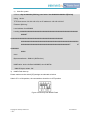
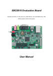
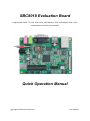
SBC8018 Evaluation Board
Integrated with SATA, TF, OTG, Audio in/out, USB, Ethernet, LCD, CCD/COMS, Serial, JTAG
interface based on 32-bit microcontroller
Quick Operation Manual
Copyright © 2011 by element14
-1-
User Manual
Version update records:
Version
Date
Description
1.0
2011.12.21
Original version
Copyright © 2011 by element14
-2-
User Manual
Contents
Chapter 1 Overview .......................................................................................................................... 4
1.1 Getting Started Quickly ....................................................................................................... 5
1.2 Development Kit Content .................................................................................................... 6
Chapter 2 Quick Setup of Development Environment ..................................................................... 8
2.1 Hardware Setup .................................................................................................................. 8
2.2 Software Setup.................................................................................................................... 9
2.2.1 Windows XP Setup ................................................................................................... 9
2.2.2 Notes for operating system image file .................................................................... 13
Chapter 3 Hands-on and Quick use of Operating System ............................................................ 14
3.1 Quick Start up with Linux system ...................................................................................... 14
3.1.1 Boot-up from Serial port ......................................................................................... 14
3.1.2 Update images from Ethernet................................................................................. 15
3.2 Quick Start up with WinCE system ................................................................................... 19
3.2.1 Flashing EBOOT to NAND Flash ........................................................................... 19
3.2.2 How to update TF Card NK runtime images .......................................................... 21
Customer Service & Technical support .......................................................................................... 29
Customer Service.................................................................................................................... 29
Technical Support.................................................................................................................... 29
Notes ....................................................................................................................................... 29
Copyright © 2011 by element14
-3-
User Manual
Chapter 1 Overview
The primary purpose of this document is to quickly understand the hardware and software
development environment for SBC8018 evaluation board, and help the user to get into the product
development faster;
1)
2)
This Document mainly has the following sections:
a)
How to use documents and CD information quickly
b)
Evaluation board hardware components and suite configuration
c)
Evaluation board hardware and software default configurations
d)
Quick setup of the development environment
e)
Hands-on and quick use of Linux/WinCE operating systems
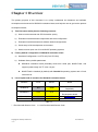
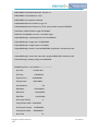
Factory default configuration of SBC8018 evaluation board
a)
Hardware Configuration: no RTC cell (Cell: CR1220)
b)
Software factory default parameters
SBC8018 evaluation board preferably boots from serial port, NAND Flash, and
support update image via TF card, net port
NAND Flash is installed (by default) with linux2.6.33 operating system and 4.3-inch
screen driver
3)
List of option add-on modules for SBC8018 evaluation board:
Modules
Linux
WinCE
Notes
WF8000-U
NO
YES#
Provided with CD-ROM
Separately
CAM8000-A
YES*
YES*
Provided with CD-ROM on
Development board
CDMA8000-U
NO
YES#
Download here
WCDMA8000-U
NO
YES#
Download here
Table 1-1
* = Provided with Source Code
Copyright © 2011 by element14
-4-
# = Not Provided with Source Code
User Manual
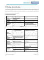
1.1 Getting Started Quickly
In this section user will learn how to understand and use SBC8018 evaluation board efficiently and
faster using SBC8018 evaluation board Quick User Manual. For more information please refer to
the document and location listed below:
For Hardware Development:
Hardware
system
Introduce CPU, expanded chip
and hardware interface
User Manual->Chapter 2 Hardware
System
CPU
Datasheet
Know principle and
configuration
CD->\HW design\datasheet\CPU\
Schematic
diagram
Know hardware principle
CD->\HW design\schematic
Dimensional
drawing
Refer to the actual dimension to
bring convenience for opening
die
User Manual->Appendix->
Appendix I Hardware Dimensions
Table 1-2
For Software Development:
Establish
testing
environment
To connect with external
hardware devices, set serial
port terminals and boots the
system
Quick Operation Manual->2 Quick
establishment of development
environment
3
Handover and quick use of
operating system
Test
functionality of
interface
Test the interface of the board
carrier through the operating
system
User Manual ->3.6.1 Various Tests
scenario
Linux developing and
compilation environment
User Manual -> 3.4.1 Establishing
operating system development
environment
WinCE developing and
compilation environment
User Manual->4.4.1 Installation of
IDE
4.4.2 Extract BSP and
project files to IDE
Recompile Linux system image
User Manual->3.4.2 System
Compilation
Recompile WinCE system
image
User Manual->4.4.3 Sysgen & Build
BSP
Establish
developing and
compilation
environment
Recompile
system image
Copyright © 2011 by element14
-5-
User Manual
Software
development
Refer to introduction of Linux
application development
process
Refer to introduction of WinCE
driver and related driver
development process
User Manual->3.7 The Development
Of Application
User Manual -> 4.4.4 Source code
path of all drivers in BSP:
Table 1-3
For Marketing:
Hardware
system
About Linux /
WinCE
software
Dimensional
drawing
CPU feature, board carrier
interface data
User Manual->Chapter 2 Hardware
System
Know basic Linux software
components and features, and
purpose of compilation tool
User
Manual->3.2
Software
Resources
3.3 Software Features
Know basic WinCE software
components and features, and
purpose of compilation tool
User Manual->4.2 Software
Resources
4.3 Software Features
Refer to the actual dimension
to bring convenience for
opening die
User Manual->Appendix-> Appendix
I Hardware Dimensions
Table 1-4
For Personal Learning Purpose:
It is suggested to browse all the sections in each chapter of this Manual..
1.2 Development Kit Content
SBC8018 evaluation board is available in two bundles; Standard and Full bundle, the kit contents
for each bundle is given below:
Standard Bundle
SBC8018 evaluation board
Serial port line (DB9-DB9)
5V@2A power adapter
Full Bundle
Standard configuration of SBC8018 evaluation suite
4.3-inch LCD display screen or 7-inch display screen (with touch screen)
Copyright © 2011 by element14
-6-
User Manual
DVD/CD Contains:
SBC8018 Quick Operation Manual
SBC8018 User Manual
Schematic Diagram, Board Carrier Chip Datasheet
Development Kit Software (Linux/WinCE)
Copyright © 2011 by element14
-7-
User Manual
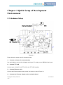
Chapter 2 Quick Setup of Development
Environment
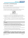
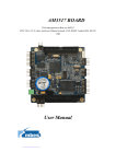
2.1 Hardware Setup
Figure 2-1
Please follow the below steps for hardware setup:
1)
Connect serial port for communication
Use serial cable to connect the debugger serial port, PC serial port and SBC8018 serial port.
2)
Connect TFT-LCD
Connect your 4.3-inch/7-inch TFT-LCD to the TFT-LCD interface.
3)
Connect Ethernet cable
Connect the Ethernet cable to the position 3 as shown in above Figure 2-1.
4)
Connect the 5V power adapter to the evaluation board
Copyright © 2011 by element14
-8-
User Manual
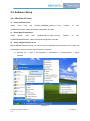
2.2 Software Setup
2.2.1 Windows XP Setup
1)
Setup Linux boot tool
Install
Linux
boot
tool
[AISgen_d800k006_Install_v1.7.exe],
location
on
CD:
on
CD:
CDROM\Linux\tools\, select the default configuration to install.
2)
Setup WinCE component
Install
WinCE
boot
tool
[dotNetFx40_Full_x86_x64.exe],
location
CDROM\WINCE600\tools\, select the default configuration to install.
3)
Setup a HyperTerminal on PC
Before SBC8018 board boot-up, you need to setup a HyperTerminal connection on PC; follow the
below steps in order to setup a Hyper Terminal connection:
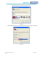
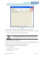
a)
Windows XP -> Start -> All Programs -> Accessories -> Communication -> Hyper
Terminal:
Figure 2-2
Copyright © 2011 by element14
-9-
User Manual
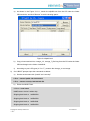
Establish HyperTerminal connection and give commands:
Figure 2-3
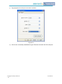
b)
Select the specific serial port from the list as per your computer COM port configuration:
Figure 2-4
Copyright © 2011 by element14
- 10 -
User Manual
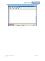
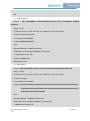
c)
Set parameters for serial port connection as below:
Figure 2-5
d)
So we have successfully established a Hyper Terminal connection with PC serial port:
Copyright © 2011 by element14
- 11 -
User Manual
Figure 2-6
Copyright © 2011 by element14
- 12 -
User Manual
2.2.2 Notes for operating system image file
Skip this step if you have purchased 4.3-inch touch screen.
If you have purchased 7-inch touch screen, you need to reprogram the kernel image file
using specified method which has been explained in section 3 “Hands-on over and Quick
Use of Operating system”.
So far, we have successfully setup hardware and software for the system, the user can now turn
on the power switch to start the development with SBC8018 evaluation board.
Copyright © 2011 by element14
- 13 -
User Manual
Chapter 3 Hands-on and Quick use of
Operating System
SBC8018 evaluation board supports two operating systems, Linux 2.6.33 and WinCE6.0. This
chapter mainly we will do hands-on over different operating systems and learn how to use OS from
serial boot and NAND Flash.
3.1 Quick Start up with Linux system
SBC8018 evaluation board by default comes with Linux + 4.3-inch screen display installed in
NAND Flash. It will boot directly without connecting TF card once it’s powered on or reset, and to
enter into the Linux system you just need to enter “root”.
Please make sure the switch [S7] settings are selected as below:
Switch S7-1 to ON position, rest switches are on OFF position..
Figure 3-1 Boot-up from NAND Flash
3.1.1 Boot-up from Serial port
1)
After the setup of hardware, make sure the switch [S7] settings are selected as below:
Switch S7-3 and S7-4 to ON position, rest switches are on OFF position.
Figure 3-2 Boot-up from Serial port
2)
Open the AISgen_d800k006_Install_v1.7.exe:
Windows XP -> Start -> All Programs -> Texas Instruments -> AISgen for D800K006 ->
UART Boot Host
Copyright © 2011 by element14
- 14 -
User Manual
Add u-boot-uart-ais.bin [Directory: CD\linux\image\] to the “AIS-File” as below:
Figure 3-3
3)
Click the “Start” and power on the evaluation board to boot-up from serial port.
4)
Wait for moment, the target window will display “(Serial Port): Closing COM1.”, close the tool
and open the Hyperterminal to catch the serial port information.
User should open Hyperterminal and Input any key to enter U-BOOT
prompts in three seconds, or else U-BOOT will load default parameter.
3.1.2 Update images from Ethernet
SBC8018 board can update images through Ethernet, insert TF card to update images with u-boot
prompts, this section manual show to update image using Ethernet.
Let’s assign the below IP’s for the PC and the evaluation board:
PC: 192.192.192.154
Evaluation board: 192.192.192.215
1)
PC TFTP service
Copyright © 2011 by element14
- 15 -
User Manual
a)
As shown in the Figure 3-1-2-1, launch the tftpd32.exe from the CD under the folder
CD\linux\tools, and click “Browse” to set the sharing space:
Figure 3-4 tftpd32 tool
b)
Copy u-boot-nand-ais.bin, uImage_4.3, uImage_7, jffs2.img from the CD under the folder
CD\linux\image\ to the folder d:\sbc8018.
c)
2)
According to your LCD types (4.3" or 7"), rename the uImage_xx as uImage.
On U-BOOT prompts input the commands as below:
a)
Set the environment with “ipaddr” and “serverip”:
U-Boot > setenv ipaddr 192.192.192.215
U-Boot > setenv serverip 192.192.192.154
b)
Erase the NAND Flash
U-Boot > nand erase
NAND erase: device 0 whole chip
Skipping bad block at 0x0ff80000
Skipping bad block at 0x0ffa0000
Skipping bad block at 0x0ffc0000
Skipping bad block at 0x0ffe0000
Copyright © 2011 by element14
- 16 -
User Manual
OK
c)
Write U-BOOT
U-Boot > tftp 0xc0700000 u-boot-nand-ais.bin;nand write.i 0xc0700000 0x20000
${filesize}
Using device
TFTP from server 192.192.192.154; our IP address is 192.192.192.215
Filename 'u-boot-nand-ais.bin'.
Load address: 0xc0700000
Loading: ###############
done
Bytes transferred = 210860 (337ac hex)
NAND write: device 0 offset 0x20000, size 0x337ac
210944 bytes written: OK
U-Boot > nandecc sw
SW ECC selected
d)
Write kernel
U-Boot > tftp 0xc0700000 uImage;nand write.i 0xc0700000 0x200000 ${filesize}
Using device
TFTP from server 192.192.192.154; our IP address is 192.192.192.215
Filename 'uImage'.
Load address: 0xc0700000
Loading: #################################################################
#################################################################
###########################
done
Bytes transferred = 2299460 (231644 hex)
NAND write: device 0 offset 0x200000, size 0x231644
2299904 bytes written: OK
Copyright © 2011 by element14
- 17 -
User Manual
e)
Write file system
U-Boot > tftp 0xc2000000 jffs2.img;nand write.i 0xc2000000 0x600000 ${filesize}
Using device
TFTP from server 192.192.192.154; our IP address is 192.192.192.215
Filename 'jffs2.img'.
Load address: 0xc2000000
Loading: #################################################################
######T
###########################################################
#################################################################
#######################################################T
#########
#####
done
Bytes transferred = 3889116 (3b57dc hex)
NAND write: device 0 offset 0x600000, size 0x3b57dc
3889152 bytes written: OK
3)
NAND Flash boot-up
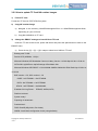
Please make sure the switch [S7] settings are selected as below:
Switch S7-1 to ON position, the rest switches should be in OFF position.
Figure 3-5 Boot-up from NAND Flash
Copyright © 2011 by element14
- 18 -
User Manual
#T
3.2 Quick Start up with WinCE system
3.2.1 Flashing EBOOT to NAND Flash
EBOOT can be downloaded to NAND Flash using sfh_OMAP-L138.exe (to run this you need .net
framework, please install dotNetFx40_Full_x86_x64.exe from Microsoft).
1)
Make sure the connection established using serial cable between evaluation board and PC.
2)
Switch S7-3 and S7-4 to ON position, rest switches should be to OFF position.
Figure 3-6 Boot-up from Serial port
3)
Copy the folder “bin” from the CD (folder CD\WINCE600\tools) to the folder D:\sbc8018.
4)
Depending on your LCD size, copy the EBOOTNANDFLASH.nb0 from the CD (folder
WINCE600\Image\4_3INCH or WINCE600\image\7INCH) to the folder D:\sbc8018\bin.
5)
Click Start -> All Programs -> run, and input “CMD” command on the pop-up dialog to enter
into the Windows Command Prompt(cmd.exe), after that enter the following commands as
below:
d:
cd \sbc8018
6)
Run the flash tool to erase the NAND Flash: (change COM port if required)
sfh_OMAP-L138.exe -erase -targetType AM1808 -flashType NAND -p COM1
7)
Now power ON the Kit, you should see the Erase sequence starts and the progress will be
displayed on the screen, wait until it completes, and then power OFF the kit.
Note: If the erase sequence does not complete after 30 seconds press a key to terminate the
sfh_OMAP-L138.exe program and continue with the flashing procedure.
8)
Run the flash tool to write an appropriate UBL (First Bootloader) and EBOOT to flash (change
COM port if required).
sfh_OMAP-L138.exe -flash -targetType AM1808 -flashType NAND -v -p COM1
-appStartAddr
0xc7f60000
Copyright © 2011 by element14
- 19 -
-appLoadAddr
0xc7f60000
arm-nand-ais-456mhz.bin
User Manual
EBOOTNANDFLASH.nb0
9)
Power ON the Kit, you should see the write sequence starts and the progress will be
displayed on the screen, wait until it completes.
Figure 3-7
10) Power OFF the Kit and set DIP switches S7-1 to ON, all others to OFF.
Figure 3-8
11) Start the serial terminal application (115200 baud, 8N1)
12) Power ON the Kit and you will see that the board will boot with the new EBOOT image.
Copyright © 2011 by element14
- 20 -
User Manual
3.2.2 How to update TF Card NK runtime images
1)
Format TF card
Format the TF Card in FAT/FAT32 file system.
2)
Copy NK runtime image
a)
Navigate to the directory WINCE600/image/lcd7inch or WINCE600/image/lcd4.3inch,
depending on your LCD size.
b)
3)
Copy NK.nb0/NK.bin to TF card.
Change the EBOOT settings to boot NK from TF Card
Insert the TF card to the kit slot, power ON the kit and press the space button to enter to the
EBOOT menu.
Press the key [2] -> [2] -> [2] in steps to select boot “NK from TF card”
a)
Booting with TI UBL
Device OPP (456MHz, 1.3V)01
Microsoft Windows CE Bootloader Common Library Version 1.4 Built Sep 23 2011 15:29:43
INFO:OALLogSetZones: dpCurSettings.ulZoneMask: 0xb
Microsoft Windows CE EBOOT 1.0 for AM1808 OMAPL138/AM18X EVM. Built Sep 23 2011 at
15:30:38
BSP version 1.3.0, SOC version 1.3.0
CODE : 0xC7F60000 -> 0xC7FA0000
DATA : 0xC7FA0000 -> 0xC7FE0000
STACK : 0xC7FE0000 -> 0xC8000000
Enabled OAL Log Zones : ERROR, WARN, INFO,
Platform Init done
System ready!
Preparing for download...
Predownload...
FMD: ReadID (Mfg=0x2c, Dev=0xda)
WARN: Invalid boot configuration found (using defaults)
Copyright © 2011 by element14
- 21 -
User Manual
Lan MAC: 00:08:ee:00:00:00
INFO: MAC address: 00:08:ee:00:00:00
WARN: Invalid BSP_ARGS data found (using defaults)
WARN: Unable to get hardware entropy
Hit space to enter configuration menu 2
-------------------------------------------------------------------------------Main Menu
-------------------------------------------------------------------------------[1] Show Current Settings
[2] Boot Settings
[3] Network Settings
[5] Video Settings
[6] Save Settings
[7] Peripheral Tests
[R] Reset Settings To Default Values
[0] Exit and Continue
Selection: 2
-------------------------------------------------------------------------------Boot Settings
-------------------------------------------------------------------------------[1] Show Current Settings
[2] Select Boot Device
[3] Select Boot Delay
[4] Select Debug Device
[5] Force Clean Boot
Copyright © 2011 by element14
- 22 -
User Manual
[6] Write Download RAM NK to Flash
[7] Set Device ID String
[8] Allow DSP to Boot
[0] Exit and Continue
Selection: 2
-------------------------------------------------------------------------------Select Boot Device
-------------------------------------------------------------------------------[1] EMAC
[2] NK from SD
[3] NK from NAND flash
[0] Exit and Continue
Selection (actual NK from SD): 2
Boot device set to NK from SD
b)
Press the key [0] -> [0] by step to start system boot from SD card, and you would see the
following serial port information on Hyper terminal:
-------------------------------------------------------------------------------Boot Settings
-------------------------------------------------------------------------------[1] Show Current Settings
[2] Select Boot Device
[3] Select Boot Delay
[4] Select Debug Device
[5] Force Clean Boot
[6] Write Download RAM NK to Flash
[7] Set Device ID String
Copyright © 2011 by element14
- 23 -
User Manual
[8] Allow DSP to Boot
[0] Exit and Continue
Selection: 0
-------------------------------------------------------------------------------Main Menu
-------------------------------------------------------------------------------[1] Show Current Settings
[2] Boot Settings
[3] Network Settings
[5] Video Settings
[6] Save Settings
[7] Peripheral Tests
[R] Reset Settings To Default Values
[0] Exit and Continue
Selection: 0
Device ID set to AM1808-0
BLFlashDownload: LogicalLoc - 0x01C40000
Loading from SD card
+ReadNKFromSDMMC
ReadFileFromSDMMC: reading file 'nk.bin'
SDBootPDD: PDD_SDInitializeHardware: MMCSD
SDBootMDD: SDInitializeHardware: SD card detected
SDBootMDD: SDInitializeHardware: V2.0 card detected
SDBootMDD: SDInitializeHardware: timeOut = 0
SDBootMDD: SDInitializeHardware: timeOut = 1
SDBootMDD: SDInitializeHardware: timeOut = 2
Copyright © 2011 by element14
- 24 -
User Manual
SDBootMDD: SDInitializeHardware: timeOut = 3
SDBootMDD: Card address is 1234
SDBootMDD: 4-bit data bus selected
InitMasterBootRecord: Partition 0, type 12
InitMasterBootRecord: Partition 0, FAT32, start 0x7e00, length 0x753f8200
InitPartition: Offset 0x7e00, length 0x753f8200
ReadFileFromSDMMC: file size = 16138467 bytes
UnpackBINImage: unpacking binary from 0xc2000000
UnpackBINImage: Image start = 0x80000000
UnpackBINImage: Image length = 0x102fd2c
UnpackBINImage: record 0, start=0x80000000, length=0x4, checksum=0x1eb
…….
UnpackBINImage: record 296, start=0x0, length=0x80001000, checksum=0x0
CheckCEImage: checking image at 0xc0000000
ROMHDR (pTOC = 0xc102de3c) --------------------DLL First
DLL Last
: 0x4001c001
: 0x40b5c097
Physical First
: 0x80000000
Physical Last
: 0x8102fd2c
Num Modules
:
181
RAM Start
: 0x81030000
RAM Free
: 0x8103f000
RAM End
: 0x8373f800
Num Copy Entries
:
2
Copy Entries Offset : 0x804f4fd4
Prof Symbol Length : 0x00000000
Prof Symbol Offset : 0x00000000
Num Files
Copyright © 2011 by element14
- 25 -
:
73
User Manual
Kernel Flags
: 0x00000000
FileSys RAM Percent : 0x30303030
Driver Glob Start
: 0x00000000
Driver Glob Length : 0x00000000
CPU
:
0x01c2
MiscFlags
:
0x0002
Extensions
: 0x80001070
Tracking Mem Start : 0x00000000
Tracking Mem Length : 0x00000000
------------------------------------------------
Image Start .......: 0x00000000
Image Size ........: 0x00000000
Image Launch Addr .: 0x00000000
Image ROMHDR ......: 0x00000000
Boot Device/Type ..: 3 / 6
ADEhellounch Windows Embedded CE by jumping to 0xc0000000...
Windows CE Kernel for ARM (Thumb Enabled) Built on Oct 20 2009 at 18:39:19
OEMInit: init.c built on Sep 28 2011 at 15:51:27.
BSP version 1.3.0, SOC version 1.3.0
INFO:OALLogSetZones: dpCurSettings.ulZoneMask: 0xf
WARN: Updating local copy of BSP_ARGS
Intr Init done...
Timer Init done...
+OALDumpClocks
Clock Configuration :
Reference Clock 0 .. 24000000 Hz
PLL0 ............. 456000000 Hz
PLL0:SYSCLK1 ..... 456000000 Hz (DSP Subsystem)
Copyright © 2011 by element14
- 26 -
User Manual
PLL0:SYSCLK2 ..... 228000000 Hz
(UART,EDMA,SPI,MMC/SD,VPIF,LCDC,SATA,uPP,USB2.0,HPI,PRU)
PLL0:SYSCLK3 ..... 91200000 Hz (EMIFA)
PLL0:SYSCLK4 ..... 114000000 Hz (INTC, SYSCFG, GPIO, PSC, I2C1, USB1.1,
EMAC/MDIO, GPIO)
PLL0:SYSCLK5 ..... 152000000 Hz (reserved)
PLL0:SYSCLK6 ..... 456000000 Hz (ARM Subsystem)
PLL0:SYSCLK7 ..... 76000000 Hz (EMAC)
PLL0:AUXCLK ......
24000000 Hz (I2C0, Timers, McASP0 serial clock, RTC, USB2.0
PHY)
PLL1 ............. 264000000 Hz
PLL1:SYSCLK1 ..... 264000000 Hz (DDR2/mDDR PHY)
PLL1:SYSCLK2 ..... 132000000 Hz (Optional for: McASP0,McBSP,ePWM,eCAP,SPI1)
PLL1:SYSCLK3 ..... 88000000 Hz (PLL0 input)
-OALDumpClocks
-OEMInit
PINMUX14=0x00000000
PINMUX15=0x00000000
PINMUX16=0x22222200
PINMUX17=0x22222222
PINMUX18=0x22000022
PINMUX19=0x02000022
OEMGetExtensionDRAM: Added 0x84400000 -> 0x88000000
OEM: Cleaning system hive
OEM: Cleaning user profiles
WARN: Updating local copy of BSP_ARGS
OEM: Not cleaning system hive
FMD: ReadID (Mfg=0x2c, Dev=0xda)
MICBIASHardwareContext::Init 555
Copyright © 2011 by element14
- 27 -
User Manual
Adapter's MAC address is 00:08:EE:00:00:00
SDHC +Init
SDHC Active RegPath: Drivers\Active\21
+SDHCPDD_Init: Ctrl 0, Entry
SDHC -Init
SDHC +Open
SDHC +Open
SDHC_CARD_DETECT = 1
SDHC CommandCompleteHandler: Command response timeout
SDHC CommandCompleteHandler: Command response timeout
SDHC CommandCompleteHandler: Command response timeout
SDHC CommandCompleteHandler: Command response timeout
SDHC CommandCompleteHandler: Command response timeout
SDHC CommandCompleteHandler: Command response timeout
SDHC CommandCompleteHandler: Command response timeout
SDHC CommandCompleteHandler: Command response timeout
Copyright © 2011 by element14
- 28 -
User Manual
Customer Service & Technical support
Customer Service
Please contact Premier Farnell local sales and customer services staffs for the help.
Website: http://www.farnell.com/
Technical Support
Please contact Premier Farnell local technical support team for any technical issues through the
telephone, live chat & mail, or post your questions on the below micro site, we will reply to you as
soon as possible.
Centralized technical support mail box: [email protected]
Community: http://www.element14.com/community/docs/DOC-41892
Notes
This board was designed by element14’s design partner- Embest, you can contact them to get the
technical support as well.
Marketing Department:
Tel: +86-755-25635656 / 25636285
Fax: +86-755-25616057
E-mail: [email protected]
Technical Support:
Tel: +86-755-25503401
E-mail: [email protected]
Copyright © 2011 by element14
- 29 -
URL: http://www.armkits.com
User Manual