1
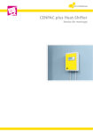
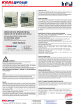
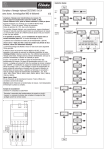
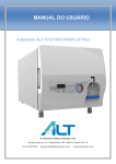
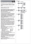
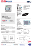
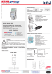
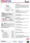
© KRALgroup - N_a 20131207 - ISC35all-v2 KRALmeter-3 made of clear polycarbonate and is captive glued to the upper part of the meter. For the dimensions please see "Data" section. CONNECTIONS Terminal No.: Terminal 1 Terminal 3 Terminal 4 Terminal 6 .cz Terminal 7 Terminal 9 Terminal 11 IS-C 35.65LE MID; IS-C 35.65LD MID; IS-C 35.80LE MID; IS-C 35.80LD MID Electronic, 4-wires, three-phase kWh meter with MID type test approval Terminal 13 Terminal 15 Terminal 20 Terminal 21 with changes valid to: 7.12.2013 Features and specifications are subject to change. USER MANUAL Meinlinova 309 CZ-190 16 Praha 9 - Koloděje TAR TAR S0+ S0- : 602 360 501(2) : 281 970 988 : [email protected] http://www.kralgroup.cz LED kWh 1234567 © KRALgroup ! Description Connection input current and voltage L1 wire phase 1 (230 V) measured wire phase 1 output current L1 (230 V) input current and voltage L2 wire phase 2 (230 V) measured wire phase 2 output current L2 (230 V) input current and voltage L3 wire phase 3 (230 V) measured wire phase 3 output current L3 (230 V) output voltage neutral of the supply (0 V) tariff signal input passive control input (only with IS-C ... LD) (230 V) tariff signal input passive control input (only with IS-C ... LD) (230 V) potential-free passive pulse output S0+ pulse output (24 V) potential-free passive pulse output S0pulse output (24 V) LED WARNING! Device installation and use must be carried out only by qualified staff. Switch off the voltage before device installation. The content and the technical specification of this User Manual are subject to change without prior notice. They do not represent any contractual obligation. KEEP THIS INSTRUCTION MANUAL - CONTAINS, I.A., EU-DECLARATION OF CONFORMITY L1 L1 L2 L2 L3 L3 N TERMINALS GENERAL DESCRIPTION The three-phase energy meter of series IS-C 35.XX is electronic, fully operating device for direct measurement and recording of active electric energy consumption in three-phase electricity power distribution systems. The energy meter requires no additional auxiliary power supply and is equipped with an optical test output, potential-free electrical pulse output for transmission of electrical pulses with a fixed time period and with LCD register for recording of the measured energy consumption. The meter is designed for use in low voltage distribution system of electricity power distributors. External housing with size of 5 modules (5-TE) on standard DIN rail can be easily installed in small electric switchboards to be direct connected for measuring the energy consumption up to 65, resp. 80A. IS-C 35.XX meets the requirements of EN 50471-1:2006 and EN 504703:2006 standards in accuracy class " B". With type test approval (MID Module B) No.: DE-08-MI003-PTB003 valid up-to 22.06.2013 the series IS-C 35.XX can be used for billing metering of electricity consumption. METER ASSEMBLY AND INSTALLATION Assembly and installation of energy meters is arbitrary and do not effect on accuracy or function for their usage. Nevertheless, as the standard the energy meters should be mounted vertically on horizontal fixed DIN rail with a width of 35 mm. Installation on the meter board according to DIN 43853 standard is not possible without using an adapter. METER HOUSING AND TERMINAL COVERS Meter terminal and housing covers are made of a polycarbonate blend containing from about 6% sodium proportion of glass fibers. The housing parts are locked and bolted in the manufacturing process. Window on the counter meter is Meter terminals for connecting current and voltage are accessible in the lower part of the meter housing through approximately rectangular holes of 6.5 mm x 7 mm size, either for connection of twisted wires slipped into copper tubes with a maximum cross-section up to 16 mm2 or solid copper connections wire with a maximum cross section of 25 mm2. Screw terminals for connecting current and voltage are head rolled, thread M6 designed for screwdriver No . PH2. Tightening torque is approx.. 3.0 Nm max. Tariff control and pulse S0 output terminals are designed approximately with a circular hole of 3 mm in diameter for connecting the coiled wire (area of cable) inserted into the copper tubes with a maximum cross section of 1.5 mm2 or in connection full copper wire with a maximum cross section 2,5 mm2. Screw terminals for tariff control and pulse output terminal screws are rolled flat head screw M2,5 for flat screwdriver size 0,6 x3,5. Tightening torque is approx.. 0.4 Nm max. METER DESIGN Electronic parts and components inside the meter are covered with an insulating varnish and thus are the most protected against climatic influences. The internal power supply is provided via capacitive three-phase power supply and ensures meter operation even if only connected between phase and neutral as well as between the phases without neutral. Internal consumption meter is low and is mainly due to capacitive reactive energy. Self- heating done by electric current flow practically does not occur. Meter measuring is determined by the applied voltage level and the current passing through resistors which reduce the primary variables so that they can be processed electronically. This enables to measure very small values. © KRALgroup Meinlinova 309 CZ-190 16 Praha 9 - Koloděje +420 602 360 502 +420 602 360 501 +420 281 970 988 http://www.kralgroup.cz [email protected] [email protected] 003TP.01 KRALmeter-3 Processing of measured values is performed in a special integrated circuit for the measurement of energy consumption, which ensures a very good measurement properties of the meter. Calculation and control functions are performed in a programmable microchips from which data are transferred via an optical test port " RL " (LED ) and electrical output of type " S0 " and to meter display. Electric pulse output is potential free and galvanic separated from current and voltage inputs and outputs. Control switch tariff consumption is provided by power supply voltage (within the parameters limit) between phase and neutral, with the use of this control voltage has no retroactive effect on the functional characteristics of the meter or measuring. Double tariff meters are equipped by additional device to interrupt current flow and voltage and potential-free pulse output for controlling the switching rate. This auxiliary device is activated during operation beyond the values limit of the voltage and current tariff switching off functions. This device does not have any retroactive effect on the functional characteristics of the meter or measuring. METER FUNCTIONS BASIC METER FUNCTIONS The meter has no externally accessible adjustment or settings. Red flashes LED test output depends on the power consumption based on connecting active energy load on meter terminals. Slowly flashing LEDs corresponds to a small consumption and quick to a large electricity consumption. In case of continuous LED lighting, the meter is either in standstill and or with activated reverse running stop, both of which means, that no energy is taken on meter output and or meter detects improper energy flow and is not connected according to wiring diagram (reversed terminal connection for input and output wires). In both cases, the counter does not emit electrical pulses and the counter does not register energy. Electric pulse output terminal 20 and terminal 21 are of the same tact as a red test diode. These pulses are electrically passive - comparable to mechanical contact - and must be processed converter by A/D operating DC voltage of 27 V and or a current of 27 mA max. At standstill of the meter, the electrical output contact remains open and does give at this time no impulses. The meter register records the energy flow measured in value of kilowatt-hours (kWh). In case of mechanical register - the last digit, marked by red color, records consumption 0.1 times the kilowatt-hours (0.1 kWh = 100 Wh). In case of LCD register the displayed number after the decimal point records 0.1 times the consumption of kilowatt hours (0.1 kWh = 100 Wh). According to the meter pulse constant (1000 pulses/kWh = 1 Wh/pulse) the LED flashes 100 times, until the register changes for one higher number. DOUBLE TARIFFS DESIGN Energy meter in double-tariffs execution (only type IS-C … LD with LCD register) has additionally terminals no. 13 and 15 to control the tariff switching, which allows to measure the electricity consumption in the two separate energy registers from which always one is active. The active tariff is shown on the LCD in the bottom right, which currently measures the energy consumption. A flashing displayed symbol "T1" represents the current registration in the energy tariff 1, while LCD display, this counter displays. A flashing displayed symbol "T2" represents the current registration in the energy tariff 2, while LCD display, this counter displays. To display the tariff that is not displayed, use the key “call” (“Aufruf”), which is necessary to press for less than 2 seconds. The display returns automatically in the currently registered active tariff within 10 seconds after pressing the key “call” (“Aufruf”) and or once measured consumption increases the value of register by one number above. A permanently displayed (non-flashing) symbol "T1" indicates the instant status of electricity consumption in tariff 1, as well as permanently displayed (non-flashing) symbol "T2" indicates the instant status of electricity consumption in tariff 2. kWh 888888,8 T1 888888,8T2kWh Mode 6+1 shows Tariff 1 register Mode 6+1 shows Tariff 2 register COMMISSIONING The electrical wiring and standards for energy meter installation must be strictly kept. Work on the electrical equipment may only be performed by the experienced specialist. After energy meter connecting on voltage the red LED “RL” starts and remains light continuously (without flashing), which is located on the front cover of the energy meter cover. Energy meter register and pulse output will remain inactive. After connecting an electric appliance on the side of power output the energy meter starts to measure the electricity consumption (in case of its proper electrical wiring) and register the consumed energy. At the same time the red LED, which continuously lighted before connecting the appliance, starts periodically flashing at the intensity depending on the value of the electricity flow. If the power consumption is low, it may take up to several minutes between two flashes of the red LED; if the power consumption is high, it them more LED flashes can occur in one second. After reaching the electricity consumption of 0.1 kilowatt-hours (0.1 kWh = 100 Wh) the meter register (in the active tariff) increases the digit by one number above. The control signal must be connected to terminals no. 13 and 15 in case of energy meter in double-tariffs design in order to execute the tariff switching. The active tariff can be seen only if the energy meter is not in standstill (no electricity consumption is measured); however the active tariff display has priority and occurs automatically after a short time. The terminal covers must be closed after energy meter installation into the network in order to increase the protection against contact with the electricity. In case of closed terminal covers it is possible to seal them by standard seal and wire and thus make them by higher security against unauthorised opening. SUPPORTING INFORMATION The electricity meters, series IS- C ... 35.65 80 ME ... LE ... LD are measuring instruments for electric energy metering and may be used only for this purpose for which, they are designed, tested and reliable. They are installation devices and are not designed for portable (mobile) applications. Connection method, operating, storage and environmental conditions are listed in this manual and in the case of installation must be strictly observed. Electricity meters work within their limit of technical parameters with no maintenance and without necessity for constant monitoring. Repairs and adjustments made by the user are not expected. Opening the electricity meter made by the user is not necessary and always leads to instrument destruction. To measure energy consumption, which requires device verification to the billing instrument is assumed, that after the verification any instrument opening brings the lost verification revocation and the instrument must be re-verified. Unauthorised encroachment on electricity meter or its any modification, change or technical improvement also terminate verification and manufacturer's liability for instrument defects. The electricity meters, series IS- C ... 35.65 80 ME ... LE ... LD may be used only as determined to ensure their precise function and to prevent any damage, personal injury and other dangers associated with their improper use. FRONT VIEW AND NAME PLATE Energy meter example: 88888,88T2kWh Mode 5+2 shows Tariff 1 register Mode 5+2 shows Tariff 2 register Drehstromzähler KRALmeter RL IS-C 35.80LE B Drehstromzähler IS-C 35.80LD B EN 50470 EN 50470 MXX DE-08-MI003-PTB003 XXXX 3 x 230/400V, 0,25-5(80)A, 50Hz RL/RA = 1,0Wh/Imp.: 3K6 M2/E2 Schaltung 4600 (DIN 43856); V1.4 Výrobní číslo - rok výroby Aufruf MXX DE-09-MI003-PTB008 XXXX 3 x 230/400V, 0,25-5(65)A, 50Hz RL/RA = 1,0Wh/Imp.: 3K6 M2/E2 Schaltung 4600 (DIN 43856); V1.4 Výrobní číslo - rok výroby .cz Aufruf .cz METER HOUSING AND INDICATORS The double-tariffs energy meter design enables the settings of register to the higher resolution and with the possibility to view the registered in the non-active tariff. After, short or long, pressing of the key “call” (“Aufruf”) occurs permanent (non-flashing) symbol “T1” on the LCD or alternatively symbol “T2” (tariffs do not appear together) which means that energy meter is in standstill (without energy consumption of its output); the red LED “RL” lights permanently on the energy meter at the same time. The return to the normal display (6.1 points) is done by pressing the "call" (“Aufruf”) key for more than two seconds, or automatically after 5 minutes from the time of last key press and or automatically after 5 seconds after displaying of non-active tariff together with displaying of actual active tariff. kWh 88888,88 T1 KRALmeter RL Tariffs control terminals Potential-free output terminals S0 Sealing shoe Mechanical or LCD register Sealing shoe Indicator LED Hinged terminal cover Meter nameplate Sealing shoe Sealing shoe Hinged terminal cover with wiring diagram © KRALgroup Meinlinova 309 CZ-190 16 Praha 9 - Koloděje +420 602 360 502 +420 602 360 501 +420 281 970 988 http://www.kralgroup.cz [email protected] [email protected] 003TP.02 KRALmeter-3 NAMEPLATE DESCRIPTION (example) Trademark Test output, LED RL Symbols: - three-phase system - accuracy class - standards compliance - reverse running stop Standard application RL TECHNICAL DATA Type designation KRALmeter Drehstromzähler IS-C 35.65LE MXX 3 x 230/400V, 0,25-5(65)A, 50Hz RL/RA = 1,0Wh/Imp.: 3K6 M2/E2 Schaltung 4600 (DIN 43856); V1.4 B EN 50470 DE-08-MI003-PTB003 XXXX Výrobní číslo - rok výroby EU conformity mark, type approval MID, module B The measured value (5.2 or 6.1 places) kWh Voltage, current, frequency LED pulses constant and pulse output Number of connection type Type test approval number Applied construction standards Type of connection to the electricity network DE 07-MI003 PTB003 EN 50470-1:2006 and EN 50470-3:2006 No. 4600 or 4702 according to DIN EN 43856 standard Reference voltage and frequency Un = 3×230/400 (1 ± 10 %)V, fn = 50 (1 ± 2 %)Hz Ist = 0,02A, Imin = 0,25A, Itr = 0,5A, Iref = 5A, Imax = (65)80A class B (± 1% ), alternatively class A ( ± 2%) Current limits Accuracy class (see meter imprint) Operation display / test output - optical flashing red LED Standstill / reverse running stop Display / register / memory optical LED, red permanent lighting LCD or electromechanical register 6 digits - full places for kWh and 1 decimal place (0.1 x kWh) Number of places (see meter) Pulse constant, optical (see meter imprint) Pulse constant, electrical (see meter imprint) Number of pulses / clock period accuracy Pulse output - passive electric Pulse constant - electrical Tariff control voltage (only IS-C 35.XX LD) Extended operating voltage range; conditions Measured current (see meter) Extended operating frequency range Internal power consumption in voltage circuit Apparent power consumption in voltage circuit Apparent power consumption in current circuit Actual starting current (three-/singlephase) Standard 1000 imp/kWh (1 Wh/imp) Standard 1000 imp/kWh (1 Wh/imp) At least one pulse with an integration time of 5 seconds Potential-free according to DIN EN 62053-31 standard class A and B Umax = 30VDC, Imax = 30mA , tmin = 30ms, reverse polarity protection 230 (1 ± 10%)V, 50Hz 180V up to 265V, three-phase voltage, clockwise 0,25…5(80)A, 0,25…5(65)A, 0,5…10(60)A, 0,5…10(80)A 45Hz up to 60Hz at Un and fn ≤ 0.9W per phase at Un and fn ≤ 8.0VA per phase, cosφ 0.11k at Iref ≤ 0.1VA, at Imax ≤ 2.5VA I ≈ 18 mA per phase at Un, fn and cosφ1 Higher harmonic frequencies accepted up to 4 kHz 3K6; -25°C up to +55°C, Working temperature range indoor installation annually average ≤ 75%, Maximum air humidity short-term 95%, non-condensing Environmental conditions mechanical M2, electro-magnetic E2 Electrical protection class II, Electrical protection protection insulation meter cover IP51 when closed terminal Electrical protection degree covers Design size 2, depth 55 mm, 5 units on Dimensions and meter size DIN rail (5-TE) 89.6 mm width, 92.5 mm height, 60.2 External meter dimensions mm depth on DIN rail according to EN DIN 50022 Fixing and installation standard, position-independent Internal power supply three-phase capacitor power supply Polycarbonate blended with 6 % of the Housing material fibers >PC-GF6< Size of connection wires for terminals 1 2.5 mm², max.: flexible wire 16 mm², up to 11 solid wire 25 mm² © KRALgroup Meinlinova 309 CZ-190 16 Praha 9 - Koloděje +420 602 360 502 +420 602 360 501 +420 281 970 988 http://www.kralgroup.cz [email protected] [email protected] 003TP.03 KRALmeter-3 SELECTED CONNECTION DIAGRAMS IN EXAMPLES EU-DECLARATION OF CONFORMITY: 4600 +4702 Passive Passive T1/2 + 1 3 4 6 7 9 11 20 21 13 15 S0 output DC 24V AC 230V L1 L2 L3 N 4-wire direct connection 3x 230/400V × × × × × × 4600 L1 L2 L3 N +4702 Passive Passive T1/2 + 1 3 4 6 7 9 11 20 21 13 15 S0 output DC 24V AC 230V L1 L2 L3 L1 L2 L3 × × × 3-wire direct connection 3x 230V 4600 +4702 Passive Passive T1/2 + 1 3 4 6 7 9 11 20 21 13 15 S0 output DC 24V AC 230V L1 L2 L3 L1 L2 L3 × × × 3-wire direct connection 3x 400V Product name: THREE-PHASE STATIC WATT-HOUR METER FOR TARIFF METERING OF ACTI-VE ENERGY Type designation: IS-C 35.65, …80 ME, …LE, …LD EC-Type test certificate: DE-08-MI003-PTB003 (acc. to direction MID EC no. : 2004/22/EG, module B) Number and address of notified person: (Modul B) 0102 (PTB) Physikalisch-Technische-Budesanstalt Bundesallee 100 D-38116 BRAUNSCHWEIG Metrology marking:СЄ-M12-0118 (СЄ-M12) Energy meters of series IS-C 35.XX fully conform to DIN EN 50470-01 and DIN EN 50470-3 standards, which are valid for energy meters and thereby meet the requirements on features for energy meters for accuracy class B for direct connection of electric meters. This product complies with EU Directive No. 93/68/EEC and complies with all the articles of the EC Directive 89/336/EEC for "Electromagnetic Compatibility" with regard to standards EN 55 022 + A1 + A2 and EN 61 000-4-2 - 3, -4, -5, -6, 12. Energy meters design meets the following standards: EN 50470-1Electricity metering equipment (a.c.) - Part 1: General requirements, tests and test conditions - Metering equipment (class indexes A, B and C) EN 50470-3Electricity metering equipment (a.c.) - Part 3: Particular requirements - Static meters for active energy (class indexes A, B and C) Potential-free-pulse-output fully complies with DIN EN 62053-31 for the impulse to conform to the conditions of Class A or Class B, as well as the standard DIN 43864 (changed in the meantime) for pulse output of type "S0". Energy meter meets the requirements for verification according to DIN 43856 in single-tariff connection no. 4600 or in double-tariffs connec-tion no. 4702. Energy meter external dimensions corresponds to the built-in devices of a 5-modules (5-TE) size on DIN-rail according to DIN 43880 stan-dard. Installation of the energy meters is designed for mounting on a standard DIN-rail 35 mm wide according to DIN EN 50022 standard. The electric protection class of the energy meters with terminal covers corresponds to IP51 according to DIN EN 60529 standard. Dimensions of electrical connections and tightening torque of the terminal screws electricity are given in DIN EN 60999-1 standard. The power force caused by cables and lead wires are determined according to DIN VDE 0298-4 standard. DIMENSIONS (mm) 44 12 Drehstromzähler IS-C 35.65LE 92 B EN 50470 MXX DE-08-MI003-PTB003 XXXX 3 x 230/400V, 0,25-5(65)A, 50Hz RL/RA = 1,0Wh/Imp.: 3K6 M2/E2 Schaltung 4600 (DIN 43856); V1.4 V Praze 5.05.2009 44,5 KRALmeter RL Výrobní číslo - rok výroby 90 49 5 Your partner for measuring the energy 6 x 12,5 WASTE DISPOSAL: This product may not be, at the end of its useful life, disposed of with normal house-hold waste but must be returned to a col-lection point for recycling of electronic equipment. Please check with your dealer or local authorities for disposal of the competent authority. DIN RAIL MOUNTED kWh METERS RE/CONDITIONED kWh METER PRE/PAZMENT kWh METERS CREDIT CARDS kWh METERS GSM OPERATED kWh METERS SPECIAL kWh METERS OTHERS FOR THE MEASUREMENT OF EL. ENERGY CURRENT TRANSFORMERS MEASURING POWER IN HARBORS AND ANCHORAGE SHIP (MARINAS) MEASURING POWER IN THE CAMP, IN TRADE FAIR, EXHIBITION, BUSINESS, COMMERCIAL AND ADMINISTRATIVE CENTERS ENERGY MANAGEMENT SYSTEMS (M-Bus, PLC, GSM, RS-485, EIB, INSTA-BUS) Our advice is for You with pleasure © KRALgroup Meinlinova 309 CZ-190 16 Praha 9 - Koloděje +420 602 360 502 +420 602 360 501 +420 281 970 988 http://www.kralgroup.cz [email protected] [email protected] 003TP.04