1
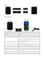
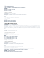
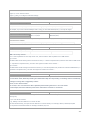
DC IN
Red
DC In (power input). Input voltage: 9V~36V. 12V suggested.
GND
Black
GND
IN
White
Input. Negative triggering. Low voltage (0V) when effective and open drain
or HIGH voltage (>1V and max. 45V) when ineffective.
OUT1
Blue
Output. Low voltage (0V) when effective and open drain when ineffective.
Output open drain sink voltage (ineffective): 45V max.
Output LOW voltage sink current (effective): 500mA max.
SW1
Yellow
SW1 connected with power switch
Note: if you need to connect it to other switch, make sure the voltage should
not over 4.5V.
SW2
Yellow
SW2 connected with power switch
Note: if you need to connect it to other switch, make sure the voltage should
not over 4.5V.
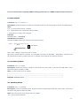
4.4 Connecting and Installation
Read this manual before using your VT300 and check if all parts are included in the packaging box.
4.4.1 Ensure that your VT300 has a working SIM installed.
- Check that the SIM has not run out of credit (test the SIM in a phone to make sure
it can send and receive SMS)
- Check that the SIM Lock code is turned off
- If you require the function of sending an SMS location report to the authorized
phone number when it makes a call to the VT300, please make sure the SIM installed
supports displaying caller ID.
Before inserting SIM card, cut off the power for VT300.
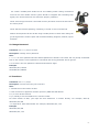
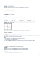
Install SIM Card
- Unscrew and remove the front cover of VT300.
- Insert the SIM card by sliding it into the card slot with the chip module facing to the
connectors on PCB.
- Put back the front cover and screw it up.
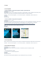
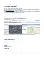
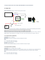
4.4.2 Antenna Connection
Connect the GSM Antenna to VT300.
Connect the GPS Antenna to VT300.
- GPS antenna is used to receive satellite signals in the sky. It should be fixed to face
the sky and should not be covered or shielded by any objects containing metal, such
as the metallic windshield.
-6-