1
BreezeLITE™
User Manual
SW Version 2.5
July 2006
P/N 213946
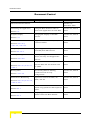
Document Control
Document Control
Topic
Description
The manual’s first release.
Date Issued
Version 1.5,
November 2005
Launching the application
Section 1.2
Graphic Display
Section 2.1
Multi-Channels
Sections 2.2.1.2.3,
Using the Base Station’s alias to
Version 2.0, March
launch the application for that BST.
2006
New graphic display of the BST
Version 2.0, March
chassis.
2006
Support of Radio Cluster, ODU, and
Version 2.0, March
Channel entities.
2006
Separating availability of radio bands
Version 2.0, March
(new HW) from SW releases.
2006
Per trap configuration of Admin
Version 2.0, March
Status, Severity and Suppression
2006
2.2.1.2.5, 2.2.1.4.3
Frequency Bands
Section 2.2.1.2.4
Per Trap Configuration
Sections 2.2.1.2.6
Cumulative Power On Time
Sections 2.2.1.3.1, 2.2.1.4.1,
2.2.2.1
Backup Files
Section 2.2.1.3.3
Performance Monitoring
Sections 2.2.1.3.5, 2.2.1.4.5,
Interval
Display of the cumulative power on
Version 2.0, March
time for NPU and AU modules and
2006
for μBST.
New backup files for filtering
Version 2.0, March
parameters and for trap
2006
configuration.
Improved counters for NPU, AU,
Version 2.0, March
μBST, and SU.
2006
Indication of reason for service
Version 2.0, March
denial: Loop problem or SU Duplicate
2006
2.2.2.5, 2.3.7
SU Service Fault Status
Section 2.3.1
SU Estimated Distance
Section 2.3.3
ii
Name.
Displaying for each SU its estimated
Version 2.0, March
distnace from the Base Station
2006
BreezeLITE User Manual
Document Control
Topic
Description
Date Issued
Filtering
Controlling traffic by
Version 2.0, March
forwarding/discarding packets
2006
Chapter 6
according to a set of rules. Support of
L2 and L3/L4 filters. Filtering is per
interface (from either network or
wireless side)
Deny List
Section 6.2.3
Hybrid VLAN Mode
Section 5.9
VLAN Transparency Mode
Section 5.7
Bridge Aging Time
Sections 2.2.1.3.1, 2.2.2.1
Maximum Tx Power (dBm)
Sections 2.2.1.2.5
SW Boot Version
Sections 2.2.1.3.1, 2.2.2.1
Temperature
Controlling traffic by discarding
Version 2.0, March
packets to/from specific MAC
2006
Addresses.
Enabling classification of both tagged
Version 2.0, March
and untagged frames.
2006
Defining the method of transferring
Version 2.0, March
packets to the operator’s upstream
2006
network.
Option of No Aging Time (null entry)
Version 2.0, March
added.
2006
A read-only display of the ODU
Version 2.5, May
maximum Tx power added.
2006
A read-only display of the NPU/μBST
Version 2.5, May
SW boot version added.
2006
Unit temperature indication added.
Version 2.5, May
2006
Sections 2.2.1.3.1,
2.2.1.4.1, 2.2.2.1
DRAP TTL Retries
Added feature.
2006
Sections 2.2.1.3.1, 2.2.2.1
SU Organization, Address,
Version 2.5, May
SU Identifiers added.
Country
Version 2.5, May
2006
Section 2.3.1
Restore Traps Defaults
Added feature.
2006
section 2.2.1.2.6
License tab
Sections 2.2.1.2.7
BreezeLITE User Manual
Version 2.5, June
Added feature.
Version 2.5, June
2006
iii
Legal Rights
Topic
Description
Date Issued
Data Port Link Speed
Corrected functionality.
Version 2.5, June
2006
Section 2.2.1.3.2
Default Service
Corrected functionality
Section 2.2.1.3.4
ODU Tx Power
ODU Tx Powerr added
Version 2.5, June
2006
Section 2.2.1.4.3
ODU Actual Frequency Band
Version 2.5, June
2006
Improved functionality-details of the
Version 2.5, June
actual band are displayed
2006
Operator and Cell IDs in AU
Added Current values of Operator ID
Version 2.5, June
Air Interface tab
and Cell ID
2006
Added Data Port Counters
Version 2.5, June
Section 2.2.1.4.3
Section 2.2.1.4.4
Data Port Counters in Micro
Base Station
2006
Section 2.2.2.5
Add New SU
Added feature.
2006
Section 2.3
Installer Password
Section 2.3.1
SU Licenses
The Installer Password is
Version 2.5, June
configurable
2006
Added feature.
Version 2.5, June
2006
Section 2.3.1
MAC Address Behind SU
Version 2.5, June
Added feature
Version 2.5, June
2006
Section 2.3.5
Downlink/Uplink Counters
QoS Profile parameters added.
Section 5.9.2
Counters description added.
Filtering
Filtering Rules in Micro Base Station
Version 2.5, June
updated
2006
Sections 6.2.1.1, 6.2.1.2
iv
Version 2.5, June
2006
BreezeLITE User Manual
Legal Rights
Legal Rights
© Copyright 2006 Alvarion Ltd. All rights reserved.
The material contained herein is proprietary, privileged, and confidential and
owned by Alvarion or its third party licensors. No disclosure thereof shall be made
to third parties without the express written permission of Alvarion Ltd.
Alvarion Ltd. reserves the right to alter the equipment specifications and
descriptions in this publication without prior notice. No part of this publication
shall be deemed to be part of any contract or warranty unless specifically
incorporated by reference into such contract or warranty.
Trade Names
Alvarion®, BreezeCOM®, WALKair®, WALKnet®, BreezeNET®, BreezeACCESS®,
BreezeMANAGE™, BreezeLINK®, BreezeCONFIG™, BreezeMAX™, AlvariSTAR™,
BreezeLITE™, MGW™, eMGW™, WAVEXpress™, MicroXpress™, WAVEXchange™,
WAVEView™, GSM Network in a Box and TurboWAVE™ and/or other products
and/or services referenced here in are either registered trademarks, trademarks
or service marks of Alvarion Ltd.
All other names are or may be the trademarks of their respective owners.
Statement of Conditions
The information contained in this manual is subject to change without notice.
Alvarion Ltd. shall not be liable for errors contained herein or for incidental or
consequential damages in connection with the furnishing, performance, or use of
this manual or equipment supplied with it.
Warranties and Disclaimers
All Alvarion Ltd. ("Alvarion") products purchased from Alvarion or through any of
Alvarion's authorized resellers are subject to the following warranty and product
liability terms and conditions.
Exclusive Warranty
With respect to the Software, Alvarion warrants the correct functionality
according to the attached documentation, for a period of fourteen (14) month from
invoice date (the "Warranty Period")". During the Warranty Period, Alvarion may
release to its Customers software updates, which include additional performance
improvements and/or bug fixes, upon availability (the "Warranty"). Bug fixes,
temporary patches and/or workarounds may be supplied as Software updates.
BreezeLITE User Manual
v
Legal Rights
Additional hardware, if required, to install or use Software updates must be
purchased by the Customer. Alvarion will be obligated to support solely the two (2)
most recent Software major releases.
ALVARION SHALL NOT BE LIABLE UNDER THIS WARRANTY IF ITS TESTING
AND EXAMINATION DISCLOSE THAT THE ALLEGED DEFECT IN THE PRODUCT
DOES NOT EXIST OR WAS CAUSED BY PURCHASER'S OR ANY THIRD
PERSON'S MISUSE, NEGLIGENCE, IMPROPER INSTALLATION OR IMPROPER
TESTING, UNAUTHORIZED ATTEMPTS TO REPAIR, OR ANY OTHER CAUSE
BEYOND THE RANGE OF THE INTENDED USE, OR BY ACCIDENT, FIRE,
LIGHTNING OR OTHER HAZARD.
Disclaimer
(a) THE SOFTWARE IS SOLD ON AN "AS IS" BASIS. ALVARION, ITS AFFILIATES
OR ITS LICENSORS MAKE NO WARRANTIES, WHATSOEVER, WHETHER
EXPRESS OR IMPLIED, WITH RESPECT TO THE SOFTWARE AND THE
ACCOMPANYING DOCUMENTATION. ALVARION SPECIFICALLY DISCLAIMS ALL
IMPLIED WARRANTIES OF MERCHANTABILITY AND FITNESS FOR A
PARTICULAR PURPOSE AND NON-INFRINGEMENT WITH RESPECT TO THE
SOFTWARE. UNITS OF PRODUCT (INCLUDING ALL THE SOFTWARE)
DELIVERED TO PURCHASER HEREUNDER ARE NOT FAULT-TOLERANT AND
ARE NOT DESIGNED, MANUFACTURED OR INTENDED FOR USE OR RESALE IN
APPLICATIONS WHERE THE FAILURE, MALFUNCTION OR INACCURACY OF
PRODUCTS CARRIES A RISK OF DEATH OR BODILY INJURY OR SEVERE
PHYSICAL OR ENVIRONMENTAL DAMAGE ("HIGH RISK ACTIVITIES"). HIGH
RISK ACTIVITIES MAY INCLUDE, BUT ARE NOT LIMITED TO, USE AS PART OF
ON-LINE CONTROL SYSTEMS IN HAZARDOUS ENVIRONMENTS REQUIRING
FAIL-SAFE PERFORMANCE, SUCH AS IN THE OPERATION OF NUCLEAR
FACILITIES, AIRCRAFT NAVIGATION OR COMMUNICATION SYSTEMS, AIR
TRAFFIC CONTROL, LIFE SUPPORT MACHINES, WEAPONS SYSTEMS OR
OTHER APPLICATIONS REPRESENTING A SIMILAR DEGREE OF POTENTIAL
HAZARD. ALVARION SPECIFICALLY DISCLAIMS ANY EXPRESS OR IMPLIED
WARRANTY OF FITNESS FOR HIGH RISK ACTIVITIES.
(b) PURCHASER'S SOLE REMEDY FOR BREACH OF THE EXPRESS
WARRANTIES ABOVE SHALL BE REPLACEMENT OR REFUND OF THE
PURCHASE PRICE AS SPECIFIED ABOVE, AT ALVARION'S OPTION. TO THE
FULLEST EXTENT ALLOWED BY LAW, THE WARRANTIES AND REMEDIES SET
FORTH IN THIS AGREEMENT ARE EXCLUSIVE AND IN LIEU OF ALL OTHER
WARRANTIES OR CONDITIONS, EXPRESS OR IMPLIED, EITHER IN FACT OR BY
OPERATION OF LAW, STATUTORY OR OTHERWISE, INCLUDING BUT NOT
LIMITED TO WARRANTIES, TERMS OR CONDITIONS OF MERCHANTABILITY,
FITNESS FOR A PARTICULAR PURPOSE, SATISFACTORY QUALITY,
vi
BreezeLITE User Manual
Legal Rights
CORRESPONDENCE WITH DESCRIPTION, NON-INFRINGEMENT, AND
ACCURACY OF INFORMATION GENERATED. ALL OF WHICH ARE EXPRESSLY
DISCLAIMED. ALVARION' WARRANTIES HEREIN RUN ONLY TO PURCHASER,
AND ARE NOT EXTENDED TO ANY THIRD PARTIES. ALVARION NEITHER
ASSUMES NOR AUTHORIZES ANY OTHER PERSON TO ASSUME FOR IT ANY
OTHER LIABILITY IN CONNECTION WITH THE SALE, INSTALLATION,
MAINTENANCE OR USE OF ITS PRODUCTS.
Limitation of Liability
(a) ALVARION SHALL NOT BE LIABLE TO THE PURCHASER OR TO ANY THIRD
PARTY, FOR ANY LOSS OF PROFITS, LOSS OF USE, INTERRUPTION OF
BUSINESS OR FOR ANY INDIRECT, SPECIAL, INCIDENTAL, PUNITIVE OR
CONSEQUENTIAL DAMAGES OF ANY KIND, WHETHER ARISING UNDER
BREACH OF CONTRACT, TORT (INCLUDING NEGLIGENCE), STRICT LIABILITY
OR OTHERWISE AND WHETHER BASED ON THIS AGREEMENT OR
OTHERWISE, EVEN IF ADVISED OF THE POSSIBILITY OF SUCH DAMAGES.
(b) TO THE EXTENT PERMITTED BY APPLICABLE LAW, IN NO EVENT SHALL
THE LIABILITY FOR DAMAGES HEREUNDER OF ALVARION OR ITS EMPLOYEES
OR AGENTS EXCEED THE PURCHASE PRICE PAID FOR THE PRODUCT BY
PURCHASER, NOR SHALL THE AGGREGATE LIABILITY FOR DAMAGES TO ALL
PARTIES REGARDING ANY PRODUCT EXCEED THE PURCHASE PRICE PAID
FOR THAT PRODUCT BY THAT PARTY (EXCEPT IN THE CASE OF A BREACH OF
A PARTY'S CONFIDENTIALITY OBLIGATIONS).
BreezeLITE User Manual
vii
Legal Rights
Important Notice
This user manual is delivered subject to the following conditions and restrictions:
This manual contains proprietary information belonging to Alvarion Ltd. Such
information is supplied solely for the purpose of assisting properly authorized
users of the respective Alvarion products.
No part of its contents may be used for any other purpose, disclosed to any
person or firm or reproduced by any means, electronic and mechanical,
without the express prior written permission of Alvarion Ltd.
The text and graphics are for the purpose of illustration and reference only.
The specifications on which they are based are subject to change without
notice.
The software described in this document is furnished under a license. The
software may be used or copied only in accordance with the terms of that
license.
Information in this document is subject to change without notice.
Corporate and individual names and data used in examples herein are
fictitious unless otherwise noted.
Alvarion Ltd. reserves the right to alter the equipment specifications and
descriptions in this publication without prior notice. No part of this
publication shall be deemed to be part of any contract or warranty unless
specifically incorporated by reference into such contract or warranty.
The information contained herein is merely descriptive in nature, and does not
constitute an offer for the sale of the product described herein.
viii
BreezeLITE User Manual
About This Manual
Alvarion's BreezeLITE is an SNMP (Simple Network Management Protocol)
application designed for on-line management of BreezeMAX system components.
This utility simplifies the installation and maintenance of small size installations
by easily enabling the change of settings or firmware upgrade for one Base
Station/Micro Base Station at a time (including the managed device's components
and associated SUs) and collecting and viewing performance data from selected
system components.
The manual is intended for personnel responsible for managing the BreezeMAX
Broadband Wireless Access system. It is assumed that the reader is familiar with
the operation and administration of BreezeMAX system components.
The manual includes the following chapters:
Chapter 1 - “Getting Started”: Provides instructions for installing BreezeLITE as
well as an overview of the BreezeLITE main window and its components.
Chapter 2 - “The Device Manager”: Describes the functionality of the Device
Manager with BreezeMAX devices, their components and the associated SUs.
Chapter 3 - “Software Upgrade”: Describes the software upgrade process of
BreezeMAX components.
Chapter 4 - “Monitoring”: Describes the monitoring capabilities, allowing the
user to view on-line information on link quality, SNR, etc. for performance
verification and problem identification. The collected performance data can be
viewed using a special Excel add-in.
Chapter 5 - “Services Provisioning”: Describes the service provisioning process
and how to configure the various service components.
Chapter 6 - “Filters”: Describes the filtering definition process for controlling
the traffic in the system by forwarding or discarding packets according to a set
of rules based on multiple allow/deny criteria.
Contents
Chapter 1 - Getting Started
1.1
Installing BreezeLITE ................................................................................................2
1.2
Introducing the BreezeLITE Window .......................................................................3
1.3
The Configuration Window .......................................................................................6
1.3.1
Add a Base Station .......................................................................................7
1.3.2
Remove a Base Station ................................................................................8
1.3.3
Importing and Exporting IP Lists ...................................................................8
1.3.4
Test and Test All ...........................................................................................9
Chapter 2 - The Device Manager
2.1
Using the Device Manager ......................................................................................12
2.2
Base Station Configuration ....................................................................................15
2.3
2.2.1
Modular Base Station .................................................................................15
2.2.2
Micro Base Station .....................................................................................49
SU Configuration .....................................................................................................61
2.3.1
SU General Tab ..........................................................................................63
2.3.2
SU Hardware Tab .......................................................................................66
2.3.3
SU Air Interface Tab ...................................................................................67
2.3.4
SU Interface Tab ........................................................................................69
2.3.5
SU Bridging Tab .........................................................................................69
2.3.6
SU Gateways Tab ......................................................................................71
2.3.7
SU Ports Counters Tab ..............................................................................71
2.3.8
SU Burst Counters Tab ..............................................................................73
Contents
Chapter 3 - Software Upgrade
3.1
Before You Start ...................................................................................................... 76
3.2
File Loading Procedure .......................................................................................... 79
3.3
Working with Log Files ........................................................................................... 81
Chapter 4 - Monitoring
4.1
Accessing the Monitor Application ....................................................................... 84
4.2
Using the Monitor Application ............................................................................... 87
4.3
Working with Log Files ........................................................................................... 88
Chapter 5 - Services Provisioning
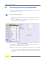
5.1
Accessing the Services Application ..................................................................... 90
5.2
Service Definition Process ..................................................................................... 92
5.2.1
5.3
Defining New Services ............................................................................... 92
Managing Service Components ............................................................................. 94
5.3.1
Adding a New Profile .................................................................................. 94
5.3.2
Modifying a Profile ...................................................................................... 94
5.3.3
Deleting a Profile ........................................................................................ 95
5.3.4
Sorting the List of Profiles .......................................................................... 95
5.3.5
Finding a Profile by Name .......................................................................... 95
5.3.6
Filters .......................................................................................................... 95
5.4
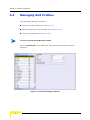
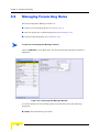
Managing QoS Profiles ........................................................................................... 96
5.5
Managing Priority Classifiers ................................................................................. 98
5.6
Managing Forwarding Rules ................................................................................ 100
5.7
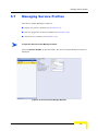
Managing Service Profiles ................................................................................... 103
5.8
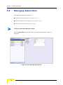
Managing Subscribers .......................................................................................... 106
5.9
Managing Services ................................................................................................ 108
5.9.1
xii
Service Tab .............................................................................................. 108
BreezeLITE User Manual
Contents
5.9.2
Down Link/Up Link Counters Tabs ........................................................... 110
5.10 Service Summary Window ................................................................................... 113
Chapter 6 - Filters
6.1
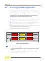
Accessing the Filters Application ....................................................................... 116
6.2
Filtering Definition Process ................................................................................. 118
6.2.1
Defining Lists of Filtering Rules ................................................................ 118
6.2.2
Interface Filtering ...................................................................................... 123
6.2.3
Deny List .................................................................................................. 129
BreezeLITE User Manual
xiii
1
Chapter 1 - Getting Started
In This Chapter:
“Installing BreezeLITE” on page 2
“Introducing the BreezeLITE Window” on page 3
“The Configuration Window” on page 6
Chapter 1 - Getting Started
1.1
Installing BreezeLITE
The executable BreezeLITE file (SSetup.exe) is available in the CD package.
Run the executable file and follow the instructions to install the BreezeLITE utility
on your PC.
The BreezeLITE utility comes with an MS Excel Add-In for easy manipulation of
monitored data.
To install the MS Excel Add-In:
1
Open MS Excel.
2
Select Tools > Add-Ins. The Add-Ins window is displayed.
3
Browse to the location of the Add-In file (BreezeLITE Monitoring.xla) and select
the file.
4
Click OK. The Add-In is displayed in the list of MS Excel Add-Ins, and a new
toolbar appears.
2
BreezeLITE User Manual
Introducing the BreezeLITE Window
1.2
Introducing the BreezeLITE Window
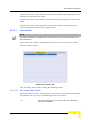
The BreezeLITE main window enables to access a wide array of monitoring and
configuration options, which are described in the following sections.
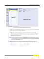
To access the BreezeLITE main window:
From the Windows Start menu, select Programs and then select BreezeLITE. Or,
in the Command prompt, type: BreezeLITE <Base Station Alias> to launch
BreezeLITE with a Base Station previously configured in the application. For
information on adding base stations to the application and defining the alias refer
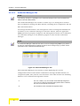
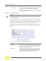
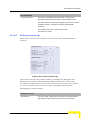
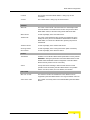
to Section 1.3.1. The BreezeLITE Main window is displayed, as shown below.
Figure 1-1: BreezeLITE Main Window
BreezeLITE User Manual
3
Chapter 1 - Getting Started
The BreezeLITE Main window comprises the following components:
Title Bar: Identifies the application's name. It also includes standard icons for
minimizing or closing the application.
BS Selection: Identifies the Alias of the selected Base Station, and enables to
select a different Base Station from the list.
Application Bar: Enables access to the various BreezeLITE applications for
configuration and monitoring of the selected Base Station. The BreezeLITE
applications include the following:
Device Manager - for configuring system components of a selected Base
Station (see Chapter 2)
SW Upgrade - for upgrading the software version of NPUs, AUs, Micro Base
Stations and SUs (see Chapter 3)
Monitor - for performance monitoring and problem identification, (see
Chapter 4)
Services - for service provisioning (see Chapter 5)
Filters - for defining filters (see Chapter 6).
NOTE
The applications become operational only after selecting a Base Station for configuration.
Toolbar: The toolbar comprises the following buttons:
Refresh: Updates the information displayed in the window according to current
values acquired from the unit.
Apply: Implements the modifications to the configuration. Exiting the configuration
utility or switching to another application without applying discards the changes.
Add: Adds a new entry.
Remove: Removes a selected entry.
Import IP List: Imports an existing list of Base Station IPs (see Section 1.3.3).
4
BreezeLITE User Manual
Introducing the BreezeLITE Window
Export IP List: Exports the list of IPs of Base Stations (see Section 1.3.3)
Start: Operational in the SW Upgrade and Monitor applications only. Starts the SW
upgrade/monitoring sessions.
Stop: Operational only in the SW Upgrade and Monitor applications or during Test
All (see below). Terminates the SW Upgrade/Monitoring/Test All sessions.
Test: Checks the status of the selected Base Station (see Section 1.3.4).
Test All: Checks the status of all the listed Base Stations (see Section 1.3.4).
Map: Displays the BreezeMAX Multi-channel Definitions Provisioning diagram in the
Device Manager application, and the Service Provisioning diagram in the Services
Application, .
Configuration Tool: Opens the Configuration window. See Section 1.3.
About: Displays the BreezeLITE’s About window, showing the application’s SW
version.
Exit: Exits the application. Exiting BreezeLITE without applying the changes,
discards the changes and closes the application.
Work Area: The display of this area varies depending on the application. Refer
to the relevant chapters for information on the actual display of this area:
Status Bar: Displays information on the status of requested activity, including
testing and monitoring cycle start time.
BreezeLITE User Manual
5
Chapter 1 - Getting Started
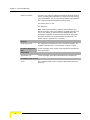
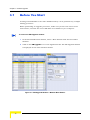
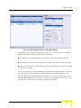
1.3
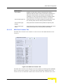
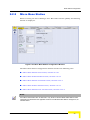
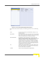
The Configuration Window
The Configuration window displays the list of Base Stations that can currently be
managed by the configuration utility, and enables to manage it.
To access the Configuration Window:
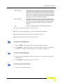
Click on the Configuration Tool on the toolbar. The Configuration window is
displayed.
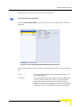
Figure 1-2: Configuration Window
The list of Base Stations comprises the following parameters:
#
6
The row number. This number is automatically assigned to any new
row. When a row is deleted, the rows are renumbered accordingly.
BreezeLITE User Manual
The Configuration Window
Alias
An alias for the Base Station. The alias can be used for opening the
BreezeLITE application with the relevant device selected.
If no alias is provided, a default alias (NoAlias) is displayed. If several
Base Stations are not provided with an alias, they will each receive a
different distinctive number.
It is recommended to define an alias to Base Stations to fascilitate
their selection from the list.
IP
The IP address of the Base Station.
Read Community
An SNMP community string used by the configuration utility when
sending an SNMP Get request to the selected Base Station.
Write Community
An SNMP community string used by the configuration utility when
sending an SNMP Set request to the selected Base Station.
Timeout (sec)
Timeout for SNMP requests. If after a period of time there is no
response from the Base Station, the request is timed out.
Test Status
Display the operational testing results of the Base Station (see
Section 1.3.4).
At initial entry after installation, the list is empty. You will need to populate the
list to manage your Base Stations.
From the Configuration window, you can:
Add a Base Station to the list (see Section 1.3.1).
Remove a Base Station from the list (see Section 1.3.2).
Import a list of Base Stations from an existing file (see Section 1.3.3).
Export the list of Base Stations as a file for backup (see Section 1.3.3).
Test the Read and Write communities status of the Base Stations (see
Section 1.3.4).
1.3.1
Add a Base Station
To add a Base Station:
1
Click Add on the toolbar to add a line to the list.
BreezeLITE User Manual
7
Chapter 1 - Getting Started
2
Enter the IP address, Read/Write community strings, Timeout, and optionally
an alias for the Base Station. If no alias is provided, a default alias (NoAlias) is
displayed.
3
Click Apply to save the changes.
NOTE
The list is automatically sorted according to the IP address.
1.3.2
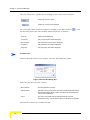
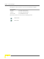
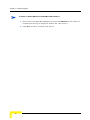
Remove a Base Station
To remove a Base Station:
1
Select a Base Station from the list.
2
Click Remove on the toolbar. A confirmation message appears:
Figure 1-3: Removing a Base Station Message
3
Click Yes to confirm the removal. The selected Base Station is removed from
the list.
1.3.3
Importing and Exporting IP Lists
You can backup your list of Base Stations with all the information displayed in the
Configuration window. When required, you can import the list into the
configuration utility of the same station or of other stations using BreezeLITE.
To export an IP list:
1
Click on Export IP List on the toolbar. The Windows Save As window is
displayed.
8
BreezeLITE User Manual
The Configuration Window
2
Browse to the desired location, enter a name for the file and click Save. The
file (.ipl) is stored in the selected folder.
To import an existing list of IPs:
1
Click on Import IP List on the toolbar. The Windows Select file window is
displayed.
2
Browse to the folder where the file (.ipl) is stored and click Open. A
confirmation message appears: “After this operation the current list will be
deleted. Are you sure you want to import a new list?”
3
Click Yes, to import the list that will replace the current list, or No to cancel
the request.
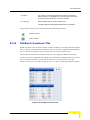
1.3.4
Test and Test All
You can check the status of the Read and Write communities of any selected Base
Station or for all Base Stations.
To test the communication status of the Read and Write communities:
Click on Communication Test/Communication Test all IP addresses on the
toolbar to test the communication status of a single selected Base Station or all
listed Base Stations respectively. The status of the test is indicated in the Status
bar. While the communication test is in progress, the status bar displays a
blinking Testing message. When testing has completed, the Status bar should
read Ready and the results are displayed in the Test Status column as two
indicators: the left indicating the test result (pass/fail) for the Read community
and the right the Write community.
A red indicator denotes a failed test and a green indicator a passed test.
BreezeLITE User Manual
9
2
Chapter 2 - The Device Manager
In This Chapter:
“Using the Device Manager” on page 12
“Base Station Configuration” on page 15
“SU Configuration” on page 61
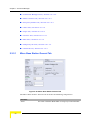
Chapter 2 - The Device Manager
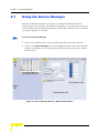
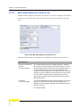
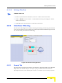
2.1
Using the Device Manager
The Device Manager enables to manage and configure BreezeMAX system
components in your network. The windows displayed vary depending on the type
of selected Base Station (whether Modular or Micro Base Station). You can switch
to any Base Station at any time.
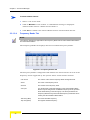
To access the Device Manager:
1
In the main window, select a Base Station from the list of Base Stations.
2
Click on the Device Manager icon on the Application Bar. The Device Manager
window is displayed for the selected Base Station (whether Modular or Micro
Base Station).
Figure 2-1: Device Manager Window - Modular Base Station
12
BreezeLITE User Manual
Using the Device Manager
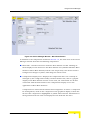
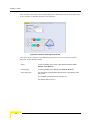
Figure 2-2: Device Manager Window - Micro Base Station
In addition to the components detailed in Section 1.2, the work area of the Device
Manager window includes the following components:
Menu Bar - Includes two menu buttons: Base Station and SU. Clicking on
them displays in the work area the Base Station view (whether Modular Base
Station or Micro Base Station) and SU view respectively. The menu button’s
background changes to yellow, indicating the selected view.
Components Display Area: Displays the components that can currently be
managed by the configuration utility. In Base Station view, this is a graphic
display of the Base Station chassis. In SU view, the units listed are all SUs
associated with the Base Station. The Components Display area is not
applicable to Micro Base Stations.
Components are selected from this list for management. To select a component
for management, click on the component in the graphical display or from the
SU list. The component is highlighted in yellow when selected. Information is
then gathered from the unit and displayed in the Selected Tab Area.
BreezeLITE User Manual
13
Chapter 2 - The Device Manager
Tab Selection Area: The Tab Selection Area comprises several tabs, each
corresponding to a work area displaying a specific group of parameters. The
tabs and the parameters displayed vary according to the selected unit type.
Selected Tab Area: The Selected Tab Area is a workspace that varies according
to the selected tab, enabling to view status or performance data and modify
specific parameters. If no unit is selected, the Selected Tab Area displays the
chassis view.
14
BreezeLITE User Manual
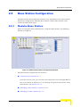
Base Station Configuration
2.2
Base Station Configuration
The Base Station Device Manager windows vary depending on the selected Base
Station for configuration: Modular Base Station or Micro Base Station. This
section describes both types.
2.2.1
Modular Base Station
When accessing the Device Manager for a modular Base Station, the following
window is displayed:
Figure 2-3: Modular Base Station Configuration Window
The Base Station Components List includes:
“Chassis View,” Section 2.2.1.1
From the chassis view, you can select the component to be managed (NPU or
AU). If no module is selected, you can manage the general parameters of the
Base Station. See Section 2.2.1.2.
“Managing a Base Station,” Section 2.2.1.2
“Managing an NPU,” Section 2.2.1.3
BreezeLITE User Manual
15
Chapter 2 - The Device Manager
“Managing an AU,” Section 2.2.1.4
2.2.1.1
Chassis View
The Chassis View window shows a graphic display of the Base Station chassis (see
Figure 2-3). The Chassis View is not applicable to Micro Base Stations.
NOTE
When clicking on Base Station on the Menu Bar, Chassis view is displayed by default. When a
module is selected, the display changes to show the selected module’s parameters. To return to
chassis view, click on Base Station in the Menu Bar.
The Chassis View allows to access the configuration windows for a selected
module (NPU, AU) by clicking on the component in the graphic display (see
Section 2.2.1.3 and Section 2.2.1.4). A faulty module is colored red.
2.2.1.2
Managing a Base Station
2.2.1.2.1
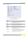
General Tab
The Modular Base Station General Tab enables to configure the Base Station
identifiers, cell parameters and ATPC parameters:
Figure 2-4: Modular Base Station General Tab
Identifiers
16
Name
The name of the Base Station. A string of up to 250 characters.
Location
The Location of the Base Station. A string of up to 250 characters.
Contact
The contact name. A string of up to 250 characters
BreezeLITE User Manual
Base Station Configuration
Cell Parameters
Configured Operator ID
A unique identifier of the network. The same Operator ID must be
defined for all Base Stations/Micro Base Stations in the network, and
it should not be used by any Base Station/Micro Base Station
belonging to another network in the same area.
The Operator ID consists of 3 groups of up to three digits each, where
the range for each group is 0 to 255.
The default Operator ID is 186.190.0.
The Operator ID is defined for all AUs in the Base Station. Updated
Operator ID is applied for each AU after resetting the AU, or after
resetting the NPU, which causes reset of all AUs.
Configured Cell ID
A unique identifier of the Base Station. The same Cell ID should not
be used by any other Base Station/Micro Base Station belonging to
the network.
The Cell ID consists of 2 groups of up to three digits each, where the
range for each group is 0 to 255.
The default Operator ID is 0.250.
The Cell ID is defined for all AUs in the Base Station. Updated
Operator ID is applied for each AU after resetting the AU, or after
resetting the NPU, which causes reset of all AUs.
ATPC Parameters
ATPC Status
Controls whether the ATPC algorithm should be used to determine
current optimal transmit level for each SU served by the Base Station.
The default is Enable.
The ATPC algorithm should always be enabled. The option to disable
it is available to enable using a fixed rate to support certain tests.
After each reset, the Base Station boots with the ATPC enabled,
disregarding its status before the device was reset.
Optimal Rx RSSI (dBm)
The Optimal Uplink RSSI sets the target level at which all
transmissions should be received by the AU-ODUs for optimal
performance.
The range is -103 to -60 (dBm).
The default is -69 dBm.
BreezeLITE User Manual
17
Chapter 2 - The Device Manager
2.2.1.2.2
Authorized Managers Tab
NOTE
The following description is applicable for the Authorized Managers tabs in both a Modular Base
Station and a Micro Base Station.
The Authorized Managers tab enables to define up to 10 management stations
that are allowed to manage the Base Station, including all its components and the
SUs associated with it.
To manage the Base Station, the management station running BreezeLITE must
be defined as an authorized manager in the Base Station, with the applicable
SNMP parameters properly configured. The management station can be defined as
an authorized manager via the Monitor program or from another authorized
manager.
NOTE
If no Authorized Manager is defined in the device, it can be managed using SNMP by any station. If
at least one Authorized Manager is defined, the device can be managed only by a station whose
parameters match a defined Authorized Manager.
Figure 2-5: Authorized Managers Tab
The Authorized Managers tab includes a table displaying the current
configuration status of all stations authorized to manage the Base Station, its
components (NPU, AUs) and the associated SUs. The table includes the following
fields for each authorized management station:
18
#
The row number (1-10). This number is automatically assigned for
every new row. When an authorized management station is deleted,
the rows are automatically renumbered.
IP
The IP Address of the authorized management station.
BreezeLITE User Manual
Base Station Configuration
Read Community
The SNMP Read Community string to be used by the authorized
manager for read-only operations. The Read Community comprises a
string of up to 23 case sensitive characters. The Read Community
serves also as the Trap Community when the station is configured to
receive traps. A null (empty) Read Community means that the Write
Community is used also for Read (get) operations.
Write Community
The SNMP Write Community string to be used by the authorized
manager for write/read operations. The Write Community comprises
a string of up to 23 case sensitive characters. A null (empty) Write
Community means that the station’s access level is defined as
read-only.
Traps
Enable or Disable sending traps to the management station.
From the Authorized Managers window you can:
Add an authorized manager to the list of Authorized Managers.
Edit the parameters of an existing authorized manager.
Remove an authorized manager from the list.
To add an Authorized Manager:
1
Click on Add on the toolbar and enter the required parameters.
2
Click Apply to apply your changes. The IP is added to the list of authorized
managers. The list is automatically sorted according to IP address.
To edit an Authorized Manager:
1
In the Authorized Managers table, double-click on a cell and enter the new
information.
2
Click Apply to send the changes to the device.
To delete an Authorized Manager:
1
Select an authorized manager.
BreezeLITE User Manual
19
Chapter 2 - The Device Manager
Click on Remove on the toolbar. A confirmation message is displayed: Remove
2
IP ‘<IP Address>’?”
Click Yes to confirm. The selected IP is removed from the list of authorized
3
managers.
IMPORTANT
Removing the management station running the configuration utility from the list of authorized
managers will disable the remote management of the Base Station.
2.2.1.2.3
Radio Clusters Tab
NOTE
The following description is applicable for the Radio Clusters tabs in both a Modular Base Station
and a Micro Base Station.
A Radio Cluster is a logical entity used to describe and support management of
the Base Station's elements associated with specific geographical sectors. A Radio
Cluster represents one or several ODUs that serve (through their directional
antennas) the same geographical sector. Up to a maximum of six Radio Clusters
can be defined per a modular Base Station, representing a cell coverage using 6 x
60° antennas. In a Micro Base Station, a maximum of four Radio Clusters can be
defined.
The Radio Cluster(s) must be defined prior to defining the relevant ODU(s), AU(s)
and Channel(s).
Figure 2-6: Radio Clusters Tab
The Radio Clusters tab includes the following parameters:
#
A number used to identify the Radio Cluster. The Radio Cluster ID is
configurable only when adding a new Radio Cluster.
The available values range from 1 to 6.
20
BreezeLITE User Manual
Base Station Configuration
Name
A string of up to 32 printable characters used as the descriptive name
of the Radio Cluster. This is an optional descriptive parameter.
The default is an empty string.
Location
A string of up to 255 printable characters used to describe the
location of the Radio Cluster. This is an optional descriptive
parameter.
The default is the string defined as the Location parameter of the
Base Station.
Heading (deg.)
The direction of the geographical sector, defined in degrees from the
north. This is an optional descriptive parameter.
The range is from 0 to 359 (degrees from north).
The default value is 0 (degrees from north).
Beam Width (deg.)
The beam width, in degrees, of the antenna(s) used in the
geographical sector. This is an optional descriptive parameter.
The range is from 0 to 359 (degrees).
The default value is 90 (degrees).
From the Radio Clusters window you can:
Add a radio cluster to the list.
Edit the parameters of an existing radio cluster.
Remove a radio cluster from the list.
To add a Radio Cluster:
1
Click on Add on the toolbar and enter the required parameters.
2
Click Apply to add the entry to the list.
To edit a Radio Cluster:
1
In the Radio Clusters table, double-click on a cell and enter the new
information.
2
Click Apply to save the changes.
BreezeLITE User Manual
21
Chapter 2 - The Device Manager
To delete a Radio Cluster:
1
Select a row in the table.
2
Click on Remove on the toolbar. A confirmation message is displayed:
“Remove Radio Cluster <Radio Cluster Name>?”
3
2.2.1.2.4
Click Yes to confirm. The selected Radio Cluster is deleted from the list.
Frequency Bands Tab
NOTE
The following description is applicable for the Frequency Bands tabs in both a Modular Base Station
and a Micro Base Station.
The Frequency Bands tab displays the list of available Frequency Bands.
Figure 2-7: Frequency Bands Tab
The Frequency Bands Configuration file defines the characteristics of each of the
frequency bands supported by the system. These characteristics include:
22
File Version
The version of the current Frequency Bands Configuration file.
Name
The name of the frequency band.
Revision
The revision of the frequency band.
Group ID
For certain bands, Channels belonging to the same AU/Micro Base
Station may be configured to use different frequency bands, provided
all the bands belong to the same group. The Group ID defines the
Frequency Bands Group, which includes frequency bands that can be
used by the same AU/Micro Base Station.
Start Freq (MHz)
The lowest downlink frequency
Stop Freq (MHz)
The highest downlink frequency
BreezeLITE User Manual
Base Station Configuration
2.2.1.2.5
Step (KHz)
The increments (resolution in KHz) of the frequency.
Duplex Separation (MHz)
The difference between downlink (Tx) and uplink (Rx) frequencies.
ODUs Tab
NOTE
The following description is applicable for the ODUs tabs in both a Modular Base Station and a
Micro Base Station.
The ODU(s) must be defined prior to defining the relevant AU(s) and Channel(s).
The ODUs tab enables viewing the status and configuration details of existing
ODUs, configuring the parameters of new ODUs including pre-configuration of
ODUs that are not yet installed, updating the parameters of existing ODUs and
deleting ODUs from the database
Upon first power-up of the modular Base Station, seven ODUs are defined
automatically, with ODU IDs from 1 to 7. In the Micro Base Station, one ODU is
defined automatically, with ODU ID 1. The parameters of these automatically
created ODUs and their default values are:
Associated Radio Cluster: NA
Tx Power: 28 dBm
ODU Configured Band: Not Defined
Admin Status: Enabled
BreezeLITE User Manual
23
Chapter 2 - The Device Manager
Figure 2-8: ODUs Tab (Modular Base Station)
The ODUs tab comprises two sections: ODUs table and the selected ODU’s details.
The ODUs table includes the following parameters:
ID
A number used to identify the ODU. The ODU ID is configurable only
when adding a new ODU.
The available values range from 1 to 24 for a Modular Base Station,
or from 1 to 4 for a Micro Base Station.
Radio Cluster
The ID of the associated Radio Cluster.
The available values range from 1 to 6 for a Modular Base Station, or
from 1 to 4 in a Micro Base Station. The value must be that of an
already defined Radio Cluster.
Tx Power (dBm)
The Tx Power parameter defines the power level of the transmitted
signal at the antenna port of the ODU.
The range is from 13 to 50 dBm using a 0.25 dBm resolution. In case
the entered value is not compatible with the installed ODU, a trap will
be issued. If the entered value is below the minimum supported by
the ODU (currently applicable only for 3.6 GHz units where the
minimum power is 18 dBm) the actual power will be set to the
minimum supported by the unit. If the entered value is above the
maximum supported by the ODU, the power will be changed to the
maximum value supported by the ODU (28 dBm for a regular ODU,
34 dBm for a High Power ODU).
The default is 28 dBm.
Admin Status
The transmit on/off status of the ODU.
The default option is Disabled.
24
BreezeLITE User Manual
Base Station Configuration
Configured Freq. Band
The Configured ODU Frequency Band will be modified through the
use of Frequency Bands Configuration file. This mechanism allows
adding new frequency bands without modifying the software by
simply loading a new Frequency Bands File when the supporting
hardware becomes available. The file will be either part of the
NPU/Micro Base Station software or loaded later to the NPU/Micro
Base Station.
The Configured ODU Frequency Band can be updated only if the
ODU is not associated with any Channel, or if the Admin Status of the
associated Channel is Disabled.
Compatibility between the Configured ODU Frequency Band and its
actual band is verified by the AU/Micro Base Station upon attempting
to associate the ODU with a Channel. If the Configured ODU
Frequency Band differs from the actual band supported by the ODU,
a mismatch trap will be sent by the AU/Micro Base Station upon
attempting to associate it with a Channel and the association will be
rejected.
Operational Status
The operational status of the ODU (Up or Down).
For a selected ODU, the following parameters are displayed:
2.2.1.2.6
Temperature (°C)
The temperature (in degrees Celsius) of the ODU.
Maximum Tx Power
(dBm)
The maximum Tx Power supported by the ODU. This read-only
parameter sets the upper limit for the Tx Power parameter.
Hardware Revision
The ODU’s Hardware revision.
Hardware Config
Description
The ODU’s Hardware configuration description
HC08 Version
The HC08 version.
CPLD Version
The CPLD version.
Serial Number
The ODU’s serial number.
Traps Tab
NOTE
The following description is applicable for the Traps tabs in both a Modular Base Station and a
Micro Base Station.
The Traps tab enables viewing current parameters of all traps and updating the
parameters of a selected trap.
BreezeLITE User Manual
25
Chapter 2 - The Device Manager
Figure 2-9: Traps Tab
The following information is displayed for each trap:
ID
The trap ID.
Name
The name of the trap.
Admin Status
The Admin Status of the trap. Double-click to edit.
Severity
The trap's severity. Double click to edit.
The available severities are Critical, Major, Minor, Warning and Info.
Suppression Interval
(sec)
The minimum time (in seconds) between consecutive transmissions
of the same trap. This parameter can be used to prevent excessive
retransmissions of the same trap. Double click to edit.
The available values are from 1 to 86,400 seconds or 0 for no
suppression, which is the default for all traps.
The three Restore to Default buttons on the top right side of the window can be
used to restore the default values for all traps. Place the cursor on a button to
view its functionality.
To restore default values:
26
BreezeLITE User Manual
Base Station Configuration
Click on the button on the left side to restore the Admin Status of all traps to the
default value (Enable for all traps).
Click on the button in the middle to restore the Severity of all traps to the default
value.
Click on the button on the right side to restore the Suppression Interval of all
traps to the default value (0 for no suppression).
2.2.1.2.7
Licenses Tab
NOTE
The following description is applicable for the Licenses tabs in both a Modular Base Station and a
Micro Base Station.
The Licenses tab enables viewing information about the current status of Base
Station and SUs licenses.
Figure 2-10: Licenses Tab
Four secondary tabs enables viewing the following details:
2.2.1.2.7.1 SUs License Bank Status
Select this option to view a table with the current status of the SUs Licenses Bank
(if available). For each entry, the following details are provided:
ID
BreezeLITE User Manual
The relevant license type. In the current version only a Bandwidth
license type is available.
27
Chapter 2 - The Device Manager
Value
The specific details of the relevant licenses. In the current version all
Bandwidth licenses are Unlimited.
Count
The number of currently available licenses (balance). Each time a
license is granted to a specific SU, the Count is decremented by one
Description
The descriptive name of the license.
2.2.1.2.7.2 Base Station Licenses
Select this option to view a table with the current status of the Base Station
Licenses (if available). For each entry, the following details are provided:
ID
The relevant license type. In the current version the following license
types (IDs) are supported:
Bandwidth license.
CPEs license (applicable only to a Micro Base Station that was
upgraded from SW version 2.0 or lower)
Value
The specific details of the relevant licenses. In the current version the
available value are:
For the Bandwidth license: Unlimited, meaning that all relevant
SUs associated with the Base Station will get unlimited bandwidth
(up to 12 Mbps).
For the CPEs (Micro Base Station): 50, 150 or 250, indicating the
number of SUs that can be supported by the Micro Base Station.
Description
The descriptive name of the license.
NOTE
In a Micro Base Station, a Value of “Grace” for Number of CPEs license (License ID = CPE),
indicates that the number of CPEs served by a Micro Base Station with no CPE license has
exceeded 20. A corresponding trap is sent. A grace period of 30 days is granted to the Micro Base
Station, starting with the registration of the 21st CPE. During this grace period it can serve more 20
CPEs. When the grace period expires, the unit will be able to serve a maximum of 20 CPEs, and will
reject any additional CPE that will try to associate with it.
The grace period is granted only to Micro Base Station that were upgraded from a SW version
below 2.5, to provide sufficient time for purchasing and loading the necessary license.
2.2.1.2.7.3 Temporary Grace Licenses
Select this option to view a table with the current status of the all Temporary
Grace Licenses (if applicable).
The aggregate uplink and downlink MIR in all the services allocated to an L model
(Limited) SU should not exceed 2 Mbps. If the aggregate MIR in the services
assigned to such an SU exceeds this limit, the Network Service Provider has a 30
28
BreezeLITE User Manual
Base Station Configuration
days grace period. During the grace period the assigned services are provided to
the SU. At any time during the 30 days grace period the Network Service Operator
can load to the SU the required permanent license for unlimited bandwidth. If a
license was not loaded during this grace period, then during the first 3 days,
defined as a temporary grace period, the Network Service Provider may change the
services assigned to the SU so that the aggregate MIR is no longer above 2 Mbps.
The SU will be removed from the list of Temporary Grace Licenses and will return
to its previous status.
For each entry, the following details are provided:
SU MAC Address
The MAC address of the relevant SU.
ID
The relevant license type. In the current version only a Bandwwidth
license type is applicable.
End Date
The expiration date of the temporary grace peiod.
2.2.1.2.7.4 Temporary Grace Licenses
Select this option to view a table with the current status of the all Grace Licenses
(if applicable).
After expiry of the 3 days temporary grace period as described above, the SU is
moved to the Grace Licenses list. After expiry of the full 30 days grace period, the
SU is moved to a list of “Grace Period Expired” SUs (even if during the grace period
the services assigned to them were changed so that the aggregate MIR is no longer
above 2 Mbps). An SU that was moved to the Grace Period Expired list will remain
in this list for 3 months. An SU that is included in this list cannot be cannot be
granted another grace period. Any attempt to assign to it a service that will bring
the aggregate MIR to a value above 2 Mbps will be rejected.
For each entry, the following details are provided:
2.2.1.3
SU MAC Address
The MAC address of the relevant SU.
ID
The relevant license type. In the current version only a Bandwidth
license type is available.
End Date
The expiration date of the grace peiod.
Status
The status of the entry.
Managing an NPU
Base Station management, including all entities associated with it (modules and
SUs) is performed via the NPU, which is the only entity that communicates
directly with the management stations. NPU management includes all parameters
BreezeLITE User Manual
29
Chapter 2 - The Device Manager
and operations that affect the NPU module only (although some operations may
indirectly affect other components as well).
To access the NPU Manager window:
In Chassis View, click on the NPU. The NPU’s slot number is highlighted in yellow
and the NPU Manager window is displayed.
The NPU Manager window includes the following tabs:
“NPU General Tab,” Section 2.2.1.3.1
“NPU Interfaces Tab,” Section 2.2.1.3.2
“Files Tab,” Section 2.2.1.3.3
“Temporary SU Tab,” Section 2.2.1.3.4
“NPU Ports Counters Tab,” Section 2.2.1.3.5
30
BreezeLITE User Manual
Base Station Configuration
2.2.1.3.1
NPU General Tab
Figure 2-11: NPU General Tab
The NPU General tab comprises the following components:
Identifiers
Name
A read-only display of the NPU’s name. The default name assigned to
the NPU by BreezeLITE is: Slot 5 NPU.
Serial #
A read-only display of the module's serial number.
Status
Status
A read-only display of the module’s operational status.
Fault Status
A read-only display of the module’s fault status.
Software
Main File
The name of the main file. Every time the NPU resets, it will reboot
using the file defined as Main.
Main Version
A read-only display of the main SW version.
Shadow File
The name of the shadow SW file. Typically, the Shadow file is the
backup file. Every time a new SW File is downloaded to the NPU, it is
stored as a Shadow file, replacing the previous Shadow file.
Shadow Version
A read-only display of the shadow SW version.
BreezeLITE User Manual
31
Chapter 2 - The Device Manager
Running Version
A read-only display of the running SW version (Main or Shadow).
Boot Version
A read-only display of the SW boot version.
Hardware
HW Version
A read-only display of the NPU HW version.
HW Description
A read-only display of the NPU HW description.
Control
Set Default
Enables to revert all NPU parameters to factory default.
WARNING - Setting the parameters of the NPU to their default values
will disable remote management of the Base Station and may result
in loss of connectivity.
Action
A drop-down menu enabling to select the SW versions control
operation to be executed by the NPU. The possible actions are:
None, Reset, Run from Shadow, Set as Main.
Bridging
Bridge Aging Time
The aging time for all addresses in the Forwarding Data Base. The
available values are from 1 to 1440 minutes or null for no aging.
Voice
DRAP TTL Retries
The limit of TTL retries for gateways that support the DRAP protocol
before concluding that the gateway is no longer active and removing
it from the database. The TTL retry time (the maximum time between
two consecutive Allocation Requests) is 255 seconds.
The range is from 1 to 100.
The default is 4.
Note - During SW download to a gateway, which may take up to
almost 15 minutes under worst conditions, the DRAP protocol is not
active. If the gateway is removed from the database before SW
download is completed, the download process will fail. During SW
download, the DRAP TTL Retries parameter should be set to its
default value of 4 (equivalent to 17 minutes).
Temperature
Temperature (°C)
A read-only display of the NPU’s temperature.
Cumulative Power On Time
Hours
32
The cumulative power-on time of the NPU since first power-up.
BreezeLITE User Manual
Base Station Configuration
2.2.1.3.2
NPU Interfaces Tab
The NPU Interfaces tab enables to view and configure parameters that affect the
operation of the Data and Management Ethernet ports.
Figure 2-12: NPU Interfaces Tab
The NPU Interfaces tab comprises the following components (fields in green are
accepted only after reset):
Data Port
IP Address
The IP address of the Data Port.
Subnet Mask
The IP subnet mask for the Data port.
Default Gateway
The default Gateway IP address for the Data port.
Management VLAN ID
The VLAN ID for management frames. If a value between 0 and 4094
is configured for the Management VLAN ID, the device will accept
management frames only if their VLAN tag has the identical value. A
value of 4095 means No VLAN. Enter 4095 or select the None check
box to accept all management frames regardless of their VLAN tag
(No VLAN).
Operational Status
A read only display of the port operational status (Up or Down).
Link Speed
The link speed: Full Duplex 100Mbps or 1 Gbps.
Management Port
IP Address
The IP address of the Management Port
CAUTION: Do not configure the IP Address of the Management port
to 0.0.0.0, as this will cause loss of management connectivity via the
DATA port.
BreezeLITE User Manual
33
Chapter 2 - The Device Manager
Subnet Mask
The IP subnet mask for the Management port.
Default Gateway
The default Gateway IP address for the Management port.
Network Destination &
Network Dest. Mask
These two parameters define the IP subnet of stations that can
manage the device when connected through a router to the
Management port. All management frames destined for addresses
belonging to this group will be routed via the Management port. All
management frames destined for other addresses will be routed via
the Data port.
Operational Status
A read only display of the port operational status (Up or Down).
Link Speed
A read only display of the current link speed and duplex (the
Management port operates a;ways in Auto Negotiation mode).
NOTE
The NPU can be managed either In Band (IB) via the Data port or Out Of Band (OOB) via the
Management port. It is highly recommended to use the Management port for local management
only. Typically the port should be down (disconnected).
The IP Addresses of the Data and Management ports must belong to different subnets.
If a Default Gateway is specified for the Management port (an address other than the 0.0.0.0
default, which means “no default gateway”), network destination parameters must be defined
as well. The network destination subnet must be different from both the Data port and the
Management port subnets.
CAUTION
Changing the parameters of the port used for remote management may result in loss of connectivity
and may disable remote management of the Base Station.
2.2.1.3.3
Files Tab
NOTE
The following description is applicable for the Files tabs in both a Modular Base Station and a Micro
Base Station.
Up to three AU SW files and three SU SW files may be stored in an NPU. In a Micro
Base Station, up to 3 SU SW files may be stored. When three SW files of a certain
type (AU or SU) are stored in the NPU/Micro Base Station, a new file cannot be
loaded until at least one of the existing files is deleted. The Files tab enables to
view the current AU and SU SW files stored in the NPU/Micro Base Station and to
delete selected file(s). It also enables instructing the NPU/Micro Base Station to
create a backup file of the configuration parameters for the entire Base Station
and its components.
34
BreezeLITE User Manual
Base Station Configuration
Figure 2-13: Files Tab (NPU)
The Files tab includes the following components:
Files
AU (not applicable for a
Micro Base Station)
A read-only list of up to 3 AU SW file names.
SU
A read-only list of up to 3 SU SW file names.
Create Backup
Backup File
The Create Backup option enables creating backup files of the Base
Station configuration. The backup file contains copies of all the
applicable configuration files and databases in the system.
The following options are available:
None: No backup file will be created.
Full: The entire Base Station configuration (excluding Passwords
and basic IP parameters of the MGMT and DATA ports - IP
Address, Subnet Mask and Default Gateway). The default file
name is backup.res.
Profiles: All the profiles associated with services (Service Profiles,
Forwarding Rules, Priority Classifiers, QoS Profiles). The default
file name is profiles.res.
Profiles and Services: All the profiles and configurations
associated with service (General Service parameters,
Subscribers, Services, Service Profiles, Forwarding Rules,
Priority Classifiers, QoS Profiles). The default file name is
profiles_srvcs.res.
BreezeLITE User Manual
35
Chapter 2 - The Device Manager
Filtering: All the configurations of Filtering Rules, Interface
Backup File (Cont.)
Filtering and Deny List. The default file name is filtering.res.
Traps: The configuration parameters for all traps. The default file
name is traps_config.res.
2.2.1.3.4
Temporary SU Tab
NOTE
The following description is applicable for the Temporary SU tabs in both a Modular Base Station
and a Micro Base Station.
The Temporary SU tab enables to define the Default SU File and Default Action.
The Default SU File is loaded to any new temporary SU when the Base Station
operates in Quick mode in order to provide to it the defined Default Service(s). The
Default Action is the action(s) to be performed with the Default File.
In addition, the tab enables to define the Service Mode (Quick or Advanced), and
the Default Services that will be available to temporary SUs in Quick Service
Mode.
Figure 2-14: Temporary SUs Tab
The Temporary SU tab includes the following components:
Control
36
Default File
The name of SU SW File that will serve as the Default File for new
temporary SUs, selectable from a drop-down menu displaying the SU
SW files in the NPU/Micro Base Station.
Default Action
A drop-down menu enabling to select the operation to be executed
with the selected default SU SW file when a new temporary SU joins
the cell when operating in Quick Mode. The possible actions are:
None, Put to Shadow, Run from Shadow, Set as Main.
BreezeLITE User Manual
Base Station Configuration
Default Service
2.2.1.3.5
Service Mode
Enables to set the service mode for temporary SUs: Quick or
Advanced. When the service mode is set to Quick, a temporary SU
will receive services based on the defined service profiles. The
combination of L2 and Voice Service Profiles is not allowed. When
set to Advanced, a temporary SU will not receive any services.
Service Profile (Type L2)
A drop-down menu of L2 service profiles for temporary SUs. To set
an L2 service profile, the Voice service profile must be None.
Service Profile (Type
PPPoE)
A drop-down menu of PPPoE service profiles for temporary SUs.
Service Profile (Type
Voice)
A drop-down menu of Voice service profiles for temporary SUs.To set
a Voice service profile, the L2 service profile must be None.
NPU Ports Counters Tab
The NPU Ports Counters tab enables to view and reset the NPU Ethernet Ports
counters.
Figure 2-15: NPU Ports Counters Tab
The NPU Ports Counters tab displays the Data (DATA) and Management (MGMT)
ports counters and enables to reset them. The information displayed for each
counter is the accumulated number since the last time the counters were reset.
BreezeLITE User Manual
37
Chapter 2 - The Device Manager
The counters are reset each time the NPU is reset, or upon activating the Reset
Counters option.
The displayed counters include:
Management Port Counters
Packets Received
The total number of packets received on the interface. Packets with
errors are not counted.
Packets Discard On Rx
Packets received from the Management port that were discarded.
Packets Tx
The total number of packets transmitted to the interface. Packets with
errors are not counted.
Packets Discard On Tx
Packets transmitted to the Management port that were discarded.
Data Port Counters
38
Total Packets Rx
The total number of packets received on the interface. Packets with
errors are not counted.
Management Packets Fw
The total number of management packets (packets whose destination
is the NPU, and broadcasts) received on the Data port and forwarded
to the NPU's internal management.
Packets Fw To Slot1
The total number of packets received from the Data port and
forwarded by the NPU to AU Slot 1.
Packets Fw To Slot2
The total number of packets received from the Data port and
forwarded by the NPU to AU Slot 2.
Packets Fw To Slot3
The total number of packets received from the Data port and
forwarded by the NPU to AU Slot 3.
Packets Fw To Slot4
The total number of packets received from the Data port and
forwarded by the NPU to AU Slot 4.
Packets Fw To Slot7
The total number of packets received from the Data port and
forwarded by the NPU to AU Slot 7.
Packets Fw To Slot8
The total number of packets received from the Data port and
forwarded by the NPU to AU Slot 8.
Packets Fw To Slot9
The total number of packets received from the Data port and
forwarded by the NPU to AU Slot 9.
Packets Discard On Rx
Packets received from the Data port that were discarded due to
switching and classification failures.
Total Packets Tx
The total number of packets transmitted to the interface. Packets with
errors are not counted.
Management Packets
Sbmt
The total number of management packets submitted by the NPU.
BreezeLITE User Manual
Base Station Configuration
Packets Sbmt From Slot1
The total number of packets received by the NPU from the AU in Slot
1 and submitted to the Data port.
Packets Sbmt From Slot2
The total number of packets received by the NPU from the AU in Slot
2 and submitted to the Data port.
Packets Sbmt From Slot3
The total number of packets received by the NPU from the AU in Slot
3 and submitted to the Data port.
Packets Sbmt From Slot4
The total number of packets received by the NPU from the AU in Slot
4 and submitted to the Data port.
Packets Sbmt From Slot7
The total number of packets received by the NPU from the AU in Slot
7 and submitted to the Data port.
Packets Sbmt From Slot8
The total number of packets received by the NPU from the AU in Slot
8 and submitted to the Data port.
Packets Sbmt From Slot9
The total number of packets received by the NPU from the AU in Slot
9 and submitted to the Data port.
The NPU Ports Counters tab also includes the following buttons:
Refresh counters
Reset counters
2.2.1.4
Managing an AU
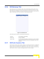
To access the AU Manager window:
In Chassis View, click on the AU to be managed. The slot number is highlighted in
yellow. The AU Manager window is displayed.
The AU Manager window includes the following tabs:
“AU General Tab,” Section 2.2.1.4.1
“AU Hardware Tab,” Section 2.2.1.4.2
“Channels Tab,” Section 2.2.1.4.3
“AU Air Interface Tab,” Section 2.2.1.4.4
“AU Ports Counters Tab,” Section 2.2.1.4.5
BreezeLITE User Manual
39
Chapter 2 - The Device Manager
2.2.1.4.1
AU General Tab
Figure 2-16: AU General Tab
The AU General tab comprises the following components:
Identifiers
Name
A read-only display of the AU’s name. The default name assigned to
the AU by BreezeLITE is: Slot # AU, where # stands for the actual slot
number.
Status
Status
A read-only display of the module’s operational status.
Fault Status
A read-only display of the module’s fault status.
Software
40
Main File
The name of the main file. This name does not necessarily include
clear identification of the SW version number. Every time the AU
resets, it will reboot using the file defined as Main.
Main Version
A read-only display of the main SW version.
Shadow File
The name of the shadow SW file. Typically, the Shadow file is the
backup file. Every time a new SW File is downloaded to the AU, it is
stored as a Shadow file, replacing the previous Shadow file.
Shadow Version
A read-only display of the shadow SW version.
Running Version
A read-only display of the running SW version.
BreezeLITE User Manual
Base Station Configuration
Voice Calls
Max No. of Calls
The maximum number of simultaneous voice calls that can be
supported by the AU.
The range is between 0 and 300.
Active Voice Calls
The number of currently active voice calls handled by the AU.
Control
Set Default
Enables to revert all AU parameters to factory default.
Action
A drop-down menu enabling to select the SW versions control
operation to be executed by the AU. The possible actions are: None,
Reset, Run from Shadow, Set as Main.
Number of Registered
SUs
A read-only display of the number of SUs registered to the selected
AU.
IDU Temperature
Temperature (°C)
A read-only display of the AU-IDU’s temperature.
Cumulative Power On Time
Hours
BreezeLITE User Manual
A read-only display of the cumulative power-on time of the selected
AU since first power-up.
41
Chapter 2 - The Device Manager
2.2.1.4.2
AU Hardware Tab
The AU Hardware tab includes read-only details on the versions of the AU IDU.
Figure 2-17: AU Hardware Tab
The AU Hardware tab includes the following components:
IDU
42
Serial #
A read-only display of the IDU serial number.
Main Card Revision
A read-only display of the main card’s revision.
Main Card Description
A read-only display of the main card’s description.
IF Card Revision
A read-only display of the IF card’s revision.
IF Card Description
A read-only display of the IF card’s description.
Boot Version
A read-only display of the IDU boot version.
BreezeLITE User Manual
Base Station Configuration
2.2.1.4.3
Channels Tab
Each AU/Micro Base Station can include up to 4 Channels. In the current release
only AUs/Micro Base Stations with 2 Channels are available. Each channel can
be connected to an ODU.
Figure 2-18: Channels Tab (AU)
The Channels tab includes the following options:
ID
The channel ID (1-4)
ODU ID
The ODU ID (1-24 in a Modular Base station, 1-6 in a Micro Base
Station) of the associated ODU.
Configured Tx Frequency
(MHz)
The Tx frequency in MHz, which must be in accordance with the
selected Bandwidth and the rules defined in the Frequency Bands
File for the frequency band selected as the Configured ODU
Frequency Band of the associated ODU.
After configuring the Downlink Frequencies f1 for an one of the
AU’s/Micro Base Station’s Channels, the Downlink Frequencies for
other Channels of the same AU/Micro Base Station should be
configured using increments of +/- 0.875 MHz from the defined
frequency: f1 +/-(N*0.875).
The Downlink Frequencies of all Channels of the same AU/Micro
Base Station should belong to the same Frequency Bands Group
BreezeLITE User Manual
43
Chapter 2 - The Device Manager
Admin Status
The Admin Status must be disabled to enable changes in the
Configured ODU Frequency Band of an associated ODU. If the
Configured ODU Frequency Band differs from the actual band
supported by the ODU, a mismatch trap will be sent by the AU/Micro
Base Station upon trying to associate it with a Channel and the
association will be rejected.
The Admin Status of all Channels belonging to the same AU/Micro
Base Station must be disabled to enable a configuration change in
the Bandwidth parameter.
Operational Status
The operational status of the ODU: Up/Down.
The Channels tab also displays the following read-only parameters for the selected
channel:
Radio Cluster
The associated radio cluster as configured in the Associated ODU.
Tx Frequency (MHz)
The downlink frequency in MHz.
Rx Frequency (MHz)
The uplink frequency in MHz, computed from the configured Downlink
(Tx) Frequency according to the Duplex Separation of the applicable
Frequency Band.
ODU Tx Power (dBm)
The Tx Power of the Associated ODU
In addition, the parameters of the actual frequency band of the ODU are shown:
ODU Actual Frequency Band
Name
The Configured ODU Frequency Band.
Revision
The revision of the ODU Frequency Band.
Group ID
For certain bands, Channels belonging to the same AU/Micro Base
Station may be configured to use different frequency bands, provided
all the bands belong to the same group. The Group ID defines the
Frequency Bands Group, which includes frequency bands that can be
used by the same AU/Micro Base Station.
Start/Stop Frequency
(MHz)
Set the boundaries of the Frequency Band.
Step Frequency (MHz)
The increments (in MHz) of the Frequencies.
Duplex Separation (MHz)
The difference between downlink (Tx) and uplink (Rx) frequencies.
Mote that due to a configuration mistake the actual ODU frequency band may
differ from the configured frequency band. The discrepancy will be detected only
upon trying to enable the Admin Status of the Channel connected to the ODU. In
this case the Admin Status of the Channel cannot be disabled.
44
BreezeLITE User Manual
Base Station Configuration
2.2.1.4.4
AU Air Interface Tab
The AU Air Interface tab enables to view and configure parameters that affect the
wireless link. The parameters in green will take effect only after reset.
Figure 2-19: AU Air Interface Tab
The AU Air Interface tab comprises the following components:
MAC Parameters
Operator ID
A read-only display of the current Operator ID.
The Operator ID is defined for all AUs in the Base Station General tab
(See Section 2.2.1.2.1). Updated Operator ID is applied for each
AU after resetting the AU, or after resetting the NPU, which causes
reset of all AUs.
Cell ID
A read-only display of the current Cell ID.
The Cell ID is defined for all AUs in the Base Station General tab (See
Section 2.2.1.2.1). Updated Cell ID is applied for each AU after
resetting the AU, or after resetting the NPU, which causes reset of all
AUs
Sector ID
(Current/Configured)
The Sector ID parameter consists of three digits in the range of 0 to
255.
The default Sector ID is 206.
BreezeLITE User Manual
45
Chapter 2 - The Device Manager
Max. Cell Radius (km)
The Maximum Cell Radius is used to adapt various timing parameters
of the MAC to the time it takes a message to reach its destination.
This time delay is dependent upon the distance between the
originating and receiving units. The timing parameters should be
adapted to the largest expected delay, which is determined from the
distance from the AU of the farthest SU served by it.
For Non-Line-Of-Sight (NLOS) links using refractions, the cell
distance should be higher than the line-of-sight distance. Typically a
10% margin is a good estimate for the increase in distance due to the
NLOS operation.
The basic time element (symbol) used by the system is 68
microseconds. This symbol size is translated to a round trip delay of
approximately 20 km, or a cell radius of 10 km. Thus, it is
recommended to set the Maximum Cell Radius using a resolution of
10 km: the actual timing of the system is the same for any cell radius
larger than N*10 km and smaller than or equal to (N+1)*10.
An SU located at a distance larger than the Maximum Cell Radius will
be rejected during the network entry process.
The values range is from 10 to 110 km. Use 10 km increments (10,
20, ….110).
The default is 20 km.
ARQ Status
(Current/Configured)
The ARQ Enable/Disable parameter controls whether to use an ARQ
algorithm for detecting errors and requesting retransmissions of
applicable unicast messages (applicable only for Best Effort and Non
Real Time services).
The default is Disable.
Multi Rate
46
Support
The Multirate Support parameter controls whether or not the multirate
algorithm will be used to determine current optimal rates in both the
uplinks and downlinks. Typically, the multirate algorithm should
always be enabled. The Disable option enables using a fixed rate,
and is intended to support special tests. After each reset, the AU
boots with Multirate Support enabled, disregarding its status before
the device was reset.
UL/DL Basic Rate
These parameters define the Basic Rate for the uplink and downlink
(see Table 2-1). The Basic Rate is the minimum rate to be used by
the Multirate algorithm. This is also the rate to be used for downlink
broadcasts and multicasts. In the uplink, this is the rate to be used by
SUs for non-scheduled transmissions, such as during the contention
period. The Basic Rate is also the initial rate to be used by the
algorithm for each new SU that joins the cell when the Multirate
algorithm is enabled.
BreezeLITE User Manual
Base Station Configuration
Bandwidth (MHz)
Current/Configured
The frequency bandwidth used by the radio. A change in the
Bandwidth parameter will take effect only after resetting the AU.
The Admin Status of all Channels belonging to the same AU must be
disabled to enable a configuration change in the Bandwidth
parameter.
The available options are 1.75 MHz and 3.5 MHz.
The default is 3.5 MHz.
2.2.1.4.5
AU Ports Counters Tab
The AU Ports Counters tab enables to view and reset the AU Ethernet Ports
counters.
Figure 2-20: AU Ports Counters Tab
The AU Ports Counters tab enables viewing or resetting the Backplane and
Wireless ports counters. The information displayed for each counter is the
accumulated number since the last time the counters were reset. The counters
are reset each time the AU is reset, or upon activating the Reset option.
The displayed counters include:
Backplane Counters
Data Bytes Rx
BreezeLITE User Manual
The total number of data bytes received from the Backplane (NPU).
Management frames and frames with errors are not included.
47
Chapter 2 - The Device Manager
Data Bytes Discard on
Rx
The number of bytes in packets discarded due to communication
errors between the AU and the NPU.
Data Bytes Tx
The total number of data bytes transmitted to the Backplane (NPU).
Management frames and frames with errors are not included.
Data Bytes Discard on Tx
This count is always 0 (No discards).
Wireless Counters
Data Bytes Rx
The total number of data bytes received from the Wireless link. MAC
management frames and frames with errors are not included.
Data Bytes Discard on
Rx
The number of bytes in packets received from the Wireless link and
discarded due to MAC protocol receive errors, such as duplicate
sequence number, wrong sequence number etc. (not CRC errors).
Data Bytes Tx
The total number of data bytes transmitted to the Wireless link. MAC
Management frames and frames with errors are not included.
Data Bytes Discard on Tx
The number of bytes in packets discarded due to congestion in the
wireless medium.
ARQ Enabled Bytes Tx
The number of bytes transmitted over BE and NRT connections.
Applicable only if the ARQ mechanism is enabled.
RTx Bytes
The number of unacknowledged bytes that were retransmitted.
Retransmissions are applicable only to BE and NRT connections
provided the ARQ mechanism is enabled.
RTx Rate (%)
Retransmission Rate in percents is defined as:
100*(Bytes Retransmitted)/(ARQ Enabled Bytes Transmitted).
The AU Ports Counters tab also includes the following buttons:
Refresh counters
Reset counters
48
BreezeLITE User Manual
Base Station Configuration
2.2.2
Micro Base Station
When accessing the Device Manager for a Micro Base Station (μBST), the following
window is displayed:
Figure 2-21: Micro Base Station Configuration Window
The Micro Base Station Configuration window includes the following tabs:
“Micro Base Station General Tab,” Section 2.2.2.1
“Micro Base Station Hardware Tab,” Section 2.2.2.2
“Micro Base Station Air Interface Tab,” Section 2.2.2.3
“Micro Base Station Interfaces Tab,” Section 2.2.2.4
“Micro Base Station Ports Counters Tab,” Section 2.2.2.5
NOTE
Some Micro Base Station tabs are identical or very similar to Modular Base Station/NPU/AU tabs.
These tabs are described in the applicable sections of the Modular Base Station management, as
indicated below.
BreezeLITE User Manual
49
Chapter 2 - The Device Manager
“Authorized Managers Tab,” Section 2.2.1.2.2
“Radio Clusters Tab,” Section 2.2.1.2.3
“Frequency Bands Tab,” Section 2.2.1.2.4
“ODUs Tab,” Section 2.2.1.2.5
“Traps Tab,” Section 2.2.1.2.6
“Licenses Tab,” Section 2.2.1.2.7
“Files Tab,” Section 2.2.1.3.3
“Temporary SU Tab,” Section 2.2.1.3.4
“Channels Tab,” Section 2.2.1.4.3
2.2.2.1
Micro Base Station General Tab
Figure 2-22: Micro Base Station General Tab
The Micro Base Station General tab includes the following components:
Identifiers
Name
50
The name of the Micro Base Station. A string of up to 255 characters.
BreezeLITE User Manual
Base Station Configuration
Location
The location of the Micro Base Station. A string of up to 255
characters.
Contact
The contact name. A string of up to 250 characters
Software
Main File
The name of the main file. This name does not necessarily include
clear identification of the SW version number. Every time the Micro
Base Station resets, it will reboot using the file defined as Main.
Main Version
A read-only display of the main SW version.
Shadow File
The name of the shadow SW file. Typically, the Shadow file is the
backup file. Every time a new SW File is downloaded to the Micro
Base Station, it is stored as a Shadow file, replacing the previous
Shadow file.
Shadow Version
A read-only display of the shadow SW version.
Running Version
A read-only display of the running SW version (Main or Shadow).
Boot Version
A read-only display of the SW boot version.
Control
Set Default
Enables to revert all Micro Base Station parameters to factory default
WARNING - Setting the parameters of the Micro Base Station to their
default values will disable remote management of the Micro Base
Station and may result in loss of connectivity.
Action
A drop-down menu enabling to select the SW versions control
operation to be executed by the Micro Base Station. The possible
actions are: None, Reset, Run from Shadow, Set as Main.
Voice Calls
Max. No. of Calls
The maximum number of simultaneous voice calls that can be
supported by the Micro Base Station. The range is between 0 and 50.
Active Voice Calls
The number of currently active voice calls handled by the Micro Base
Station.
BreezeLITE User Manual
51
Chapter 2 - The Device Manager
DRAP TTL Retries
The limit of TTL retries for gateways that support the DRAP protocol
before concluding that the gateway is no longer active and removing
it from the database. The TTL retry time (the maximum time between
two consecutive Allocation Requests) is 255 seconds.
The range is from 1 to 100.
The default is 4.
Note - During SW download to a gateway, which may take up to
almost 15 minutes under worst conditions, the DRAP protocol is not
active. If the gateway is removed from the database before SW
download is completed, the download process will fail. During SW
download, the DRAP TTL Retries parameter should be set to its
default value of 4 (equivalent to 17 minutes).
Bridging
Bridge Aging Time
The aging time for all addresses in the Forwarding Data Base. The
available values are from 1 to 1440 minutes or null for no aging.
Number of Registered
SUs
A read-only display of the number of SUs registered to the selected
Micro Base Station.
Temperature
Temperature (°C)
A read-only display of the Micro Base Station IDU’s temperature.
Cumulative Power on Time
Hours
52
The cumulative power-on time of the Micro Base Station since first
power-up.
BreezeLITE User Manual
Base Station Configuration
2.2.2.2
Micro Base Station Hardware Tab
The Micro Base Station Hardware tab includes read-only details on the versions of
the IDU.
Figure 2-23: Micro Base Station Hardware Tab
The Micro Base Station Hardware tab includes the following components:
IDU
Serial #
A read-only display of the IDU’s serial number.
Main Card Revision
A read-only display of the main card’s revision.
Main Card Description
A read-only display of the main card’s description.
IF Card Revision
A read-only display of the Micro Base Station’s IF card revision.
IF Card Description
A read-only display of the Micro Base Station IF card description.
Boot Version
A read-only display of the IDU’s boot version.
BreezeLITE User Manual
53
Chapter 2 - The Device Manager
2.2.2.3
Micro Base Station Air Interface Tab
The Micro Base Station Air Interface tab enables to view and configure parameters
that affect the wireless link. The parameters in green will take effect only after
reset.
Figure 2-24: Micro Base Station Air Interface Tab
The Micro Base Station Air Interface tab comprises the following components:
Base Station ID
Operator ID, Cell ID and
Sector ID
(Current/Configured)
The Current/Configured values for the Base Station ID. The Base
Station ID is the unique identifier of a Micro Base Station. An SU can
be authenticated by a Micro Base Station only if the Base Station ID
and Base Station ID Mask in the SU match the Base Station ID
configured in the Micro Base Station. The Base Station ID comprises
6 groups of up to three digits each, where the range for each group is
0 to 255. The first 3 groups define the Operator ID, the next two
groups define the Cell ID, and the sixth group defines the Sector ID
(Micro Base Station).
ARQ Status
(Current/Configured)
The ARQ Enable/Disable parameter controls whether to use an ARQ
algorithm for detecting errors and requesting retransmissions of
applicable unicast messages (applicable only for Best Effort and Non
Real Time services).
The default is Disable.
54
BreezeLITE User Manual
Base Station Configuration
Max. Cell Radius (km)
The Maximum Cell Radius is used to adapt various timing parameters
of the MAC to the time it takes a message to reach its destination.
This time delay is dependent upon the distance between the
originating and receiving units. The timing parameters should be
adapted to the largest expected delay, which is determined from the
distance from the Micro Base Station of the farthest SU served by it.
For Non-Line-Of-Sight (NLOS) links using refractions, the cell
distance should be higher than the line-of-sight distance. Typically a
10% margin is a good estimate for the increase in distance due to the
NLOS operation.
The basic time element (symbol) used by the system is 68
microseconds. This symbol size is translated to a round trip delay of
approximately 20 km, or a cell radius of 10 km. Thus, it is
recommended to set the Maximum Cell Radius using a resolution of
10 km: the actual timing of the system is the same for any cell radius
larger than N*10 km and smaller than or equal to (N+1)*10.
An SU located at a distance larger than the Maximum Cell Radius will
be rejected during the network entry process.
The values range is from 10 to 110 km. Use 10 km increments (10,
20, ….110).
The default is 20 km.
Multi Rate Parameters
Multirate Support
The Multirate Support parameter controls whether or not the multirate
algorithm will be used to determine current optimal rates in both the
uplinks and downlinks. Typically, the multirate algorithm should
always be enabled. The Disable option enables using a fixed rate,
and is intended to support special tests. After each reset, the Micro
Base Station boots with Multirate Support enabled, disregarding its
status before the device was reset.
UL/DL Basic Rate
These parameters define the Basic Rate for the uplink and downlink
(see Table 2-1).
Bandwidth (MHz)
Current/Configured
The frequency bandwidth used by the radio. A change in the
Bandwidth parameter will take effect only after resetting the Micro
Base Station.
The Admin Status of all Channels belonging to the Micro Base Station
must be disabled to enable a configuration change in the Bandwidth
parameter.
The available options are: 1.75 MHz and 3.5 MHz.
The default is 3.5 MHz.
BreezeLITE User Manual
55
Chapter 2 - The Device Manager
ATPC Parameters
Optimal UL RSSI (dBm)
The Optimal Uplink RSSI sets the target level at which all
transmissions should be received by the AU-ODUs for optimal
performance.
The range is -103 to -60 (dBm).
The default is -69 dBm.
ATPC Support
The Automatic Transmit Power Control (ATPC) Support parameter
controls whether or not the ATPC algorithm will be used to determine
optimal transmit level for each of the SUs served by the Micro Base
Station.
The default is Enable.
The ATPC algorithm should always be enabled. The option to disable
it is available to enable using a fixed rate to support certain tests.
After each reset, the Micro Base Station boots with the ATPC
enabled, disregarding its status before the device was reset.
56
BreezeLITE User Manual
Base Station Configuration
2.2.2.4
Micro Base Station Interfaces Tab
The Micro Base Station Interfaces tab enables to view and configure parameters
that affect the operation of the Data and Management ports.
Figure 2-25: Micro Base Station Interfaces Tab
The Micro Base Station Interfaces Tab comprises the following components (fields
in green are accepted only after reset):
Data Port
IP Address
The IP address of the Data Port.
Subnet Mask
The IP subnet mask for the Data port.
Default Gateway
The default Gateway IP address for the Data port.
VLAN ID
The VLAN ID for management frames. If a value between 0 and 4094
is configured for the Management VLAN ID, the device will accept
management frames only if their VLAN tag has the identical value. A
value of 4095 means No VLAN. Enter 4095 or select the None check
box to accept all management frames regardless of their VLAN tag
(No VLAN).
Auto Negotiation
(Current/Configured)
The current/configured Auto Negotiation status for the Ethernet
interface of the data port in the Micro Base Station.
Speed & Duplex
(Current/Configured)
The current/configured speed and duplex status for the Ethernet
interface of the data port in the Micro Base Station. The Configured
Speed & Duplex is applicable only if the Configured Auto Negotiation
is Disabled.
BreezeLITE User Manual
57
Chapter 2 - The Device Manager
Management Port
IP Address
The IP address of the Management Port.
CAUTION: Do not configure the IP Address of the Management port
to 0.0.0.0, as this will cause loss of management connectivity via the
DATA port.
Subnet Mask
The IP subnet mask for the Management port.
Default Gateway
The default Gateway IP address for the Management port.
Network Destination &
Network Dest. Mask
These two parameters define the IP subnet of stations that can
manage the device when connected through a router to the
Management port. All management frames destined for addresses
belonging to this group will be routed via the Management port. All
management frames destined for other addresses will be routed via
the Data port.
Auto Negotiation
(Current/Configured)
The current/configured Auto Negotiation status for the Ethernet
interface of the management port in the Micro Base Station.
Speed & Duplex
(Current/Configured)
The current/configured speed and duplex status for the Ethernet
interface of the management port in the Micro Base Station. The
Configured Speed & Duplex is applicable only if the Configured Auto
Negotiation is Disabled.
NOTE
The Micro Base Station can be managed either In Band (IB) via the Data port or Out Of Band
(OOB) via the Management port.It is highly recommended to use the Management port for local
management only. Typically the port should be down (disconnected).
The IP Addresses of the Data and Management ports must belong to different subnets.
If a Default Gateway is specified for the Management port (an address other than the 0.0.0.0
default, which means “no default gateway”), network destination parameters must be defined
as well. The network destination subnet must be different from both the Data port and the
Management port subnets.
CAUTION
Changing the parameters may result in loss of connectivity and may disable remote management of
the Micro Base Station.
2.2.2.5
Micro Base Station Ports Counters Tab
The Micro Base Station Ports Counters tab enables to view and reset the Micro
Base Station Ethernet Ports and Wireless Port counters.
58
BreezeLITE User Manual
Base Station Configuration
Figure 2-26: Micro Base Station Ports Counters Tab
The information displayed for each counter is the accumulated number since the
last time the counters were reset. The counters are reset each time the Micro Base
Station is reset, or upon activating the Reset Counters option.
The displayed counters include:
Management Port Counters
Packets Rx
The total number of packets received on the interface. Packets with
errors are not counted.
Packets Discard On Rx
Packets received from the Management port that were discarded.
Packets Tx
The total number of packets transmitted to the interface. Packets with
errors are not counted.
Packets Discard On Tx
Always 0. Currently packets are not discarded on Tx.
Data Port Counters
Total Bytes Rx
The total number of bytes received from the Data port, including
Management frames. Frames with errors are not included.
Data Bytes Rx
The total number of data bytes received from the Data port.
Management frames and frames with errors are not included.
Data Bytes Discarded on
Rx
The number of bytes in packets discarded due to internal
communication errors.
Total Bytes Tx
The total number of bytes transmitted to the Data port, including
Management frames. Frames with errors are not included.
Data Bytes Tx
The total number of data bytes transmitted to the Data port.
Management frames and frames with errors are not included.
BreezeLITE User Manual
59
Chapter 2 - The Device Manager
Data Bytes Discarded on
Tx
This count is always 0 (No discards).
Wireless Port Counters
Data Bytes Rx
The total number of data bytes received from the Wireless link. MAC
management frames and frames with errors are not included.
Data Bytes Discarded on
Rx
The number of bytes in packets received from the Wireless link and
discarded due to MAC protocol receive errors, such as duplicate
sequence number, wrong sequence number etc. (not CRC errors).
Data Bytes Tx
The total number of data bytes transmitted to the Wireless link. MAC
Management frames and frames with errors are not included.
Data Bytes Discarded on
Tx
The number of bytes in packets discarded due to congestion in the
wireless medium.
ARQ Enabled Bytes Tx
The number of bytes transmitted over BE and NRT connections.
Applicable only if the ARQ mechanism is enabled.
RTx Bytes
The number of unacknowledged bytes that were retransmitted.
Retransmissions are applicable only to BE and NRT connections
provided the ARQ mechanism is enabled.
RTx Rate (%)
Retransmission Rate in percents is defined as:
100*(Bytes Retransmitted)/(ARQ Enabled Bytes Transmitted).
The Micro Base Station Ports Counters tab also includes the following button:
Refresh counters
Reset counters (per counters)
60
BreezeLITE User Manual
SU Configuration
2.3
SU Configuration
This section describes the configuration of Subscriber Units associated with the
Base Station (whether Modular Base Station or Micro Base Station). Unless
otherwise specified, the various tabs are identical for both Modular Base Station
and Micro Base Station.
The SU Configuration window displays status information on the Subscriber Units
associated with the selected Base Station. Units displayed in red are
disconnected.
Figure 2-27: Subscriber Units List
The list of SUs displays the following information on each Subscriber Unit:
Name
The name of the SU.
MAC
The MAC address of the SU.
Status
The status of the SU, whether temporary or permanent.
AU
The AU to which the SU is connected (NA to Micro Base Station)
The List of SUs can be sorted by clicking on any of the column headers (Name,
MAC, Status, AU). The list is sorted in ascending order according to the selected
column. Click the column header again to sort in descending order.
BreezeLITE User Manual
61
Chapter 2 - The Device Manager
You can search for a specific SU by clicking on one of the search buttons:
Search for an SU by name.
Search for an SU by MAC address.
You can apply a filter to the list of SUs by clicking on the Filter button (
). Only
the SUs that match the selected filter will be displayed, as follows:
Show All
All SUs will be displayed.
Connected
Only connected SUs will be displayed.
Disconnected
Only disconnected SUs will be displayed.
Permanent
Only permanent SUs will be displayed.
Temporary
Only temporary SUs will be displayed.
To add an SU:
Click on the Add button in the toolbar. The New SU dialog box opens:
Figure 2-28: New SU Dialog Box
Enter the parameters of the new SU:
MAC Address
The MAC address of the SU.
SW File Name
Optional: From the drop-down menu that includes all SU SW Files in
the NPU/Micro Base Station, select the SW File to be loaded to the
SU upon first registration.
Action
The action to be taken with the selected SW Fileu pon first
registration: None, Load to Shadow, Run from Shadow, Set as Main.
The new SU is added as a Permanent SU.
62
BreezeLITE User Manual
SU Configuration
2.3.1
SU General Tab
Figure 2-29: SU General Tab
The SU General Tab includes the following components:
Identifiers
Name
The SU’s name. A string of up to 32 printable characters.
The default SU Name given to a new SU during the definition process
is SU@<SU's MAC Address>. When an SU is registered, it receives
services based on its MAC address, and the default SU Name is
replaced by the name configured in the SU (Common Name).
Under normal conditions, the SU Name should be changed only upon
identifying an SU with an SU Name that is identical to that of a
previously registered SU. In this case, the new SU will be registered
(to enable management), but will not receive any services. Its name
in the database of the serving device will be changed to SU@<SU's
MAC Address>. The system administrator will be informed of the
problem through the Service Fault Status parameter (see below) and
through a trap message (rbSuDuplicateName trap). If the
administrator decides that the SU is legitimate and should receive
services, a new SU Name must be configured. The SU will receive
services only after configuring it with a unique SU Name.
A new SU Name can be configured also for a temporary SU.
MAC Address
BreezeLITE User Manual
A read-only display of the MAC address of the SU.
63
Chapter 2 - The Device Manager
Installer Password
The installer password. The Installer Password is used for accessing
the SU's Monitor (Installer) program or web server locally, using the
SU's Ethernet port. The Installer Password consists of a string of up
to 20 printable characters, case sensitive.
SU Type
A read-only display of the SU type: CPE, PRO CPE, CPE-PRO-L or
CPE-SI.
Associated AU
The slot number of the associated AU. Not applicable for a Micro
Base Station.
Organization
A read-only display of the Organization name, as configured in the
SU.
Address
A read-only display of the SU’s Address, as configured in the SU.
Country
A read-only display of the Country name, as configured in the SU.
Status
Registration Status
A read-only display of the SU’s registration status.
Fault Status
A read-only display of the SU’s fault status.
Permanence Status
The permanence status of the SU. Available permanence statuses
are: Permanent and Temporary.
Service Fault Status
OK or reason for denying services to the SU. The reason can be:
Loop problem. A loop was detected on the Ethernet side of the
SU. rbNetworkingError Trap will be sent, and services to this SU
will be denied until resetting the SU from the network (NPU/Micro
Base Station) side (provided the problem no longer exists). The
problem is detectable through periodical (every 5 seconds)
transmissions to the Ethernet link of SNAP packets with "AA AA
03" in the header, and the destination MAC address is
00:10:E7:00:00:01. If the SU receives this packet from the
Ethernet, it means that there is a loop and the SU will send an
appropriate message to the NPU/Micro Base Station.
Duplicate SU Name: The SU Name is already in use by another
SU. rbSuDuplicateName Trap will be sent and services to the SU
will be denied until another unique name is configured for the SU.
Software
64
Main File
The name of the downloaded SW file. This name does not
necessarily include clear identification of the SW version number.
Main Version
A read-only display of the main SW version. Every time the SU
resets, it will reboot using the version defined as Main.
Shadow File
The name of the shadow SW file. Typically, the Shadow file is the
backup file. Every time a new SW File is downloaded to the SU, it is
stored as a Shadow file, replacing the previous Shadow file.
Shadow Version
A read-only display of the shadow SW version.
BreezeLITE User Manual
SU Configuration
Running Version
A read-only display of the running SW version.
Control
Set Default
Enables to revert all parameters to factory default.
Action
A drop-down menu enabling to select the operation to be executed on
the SU. The possible actions are:
Temporary SUs: None, Reset
Permanent SUs: None, Reset, Run from Shadow, Set as Main.
Cumulative Power On Time
Hours
The cumulative power-on time of the SU since first power-up.
License (L model only)
ID
The relevant license type. In the current version only a Bandwidth
license type is available.
Value
The specific details of the relevant licenses. In the current version all
Bandwidth licenses are Unlimited.
CAUTION
Reverting the parameters to factory default will result in loss of connectivity.
To add a License to an L model SU (CPE-PRO-L):
In the current release only an Unlimited Bandwidth license can be added to an L
model CPE. The Add button above the License table is available only when the
table is empty. To add an Unlimited Bandwidth license to the SU (provided a
license is available in the SUs License Bank), click on the Add button and confirm
the request.
BreezeLITE User Manual
65
Chapter 2 - The Device Manager
2.3.2
SU Hardware Tab
The SU Hardware tab includes read-only information on the versions of the IDU
and ODU.
Figure 2-30: SU Hardware Tab
The SU Hardware tab includes the following components:
66
Serial #
A read-only display of the ODU’s serial number.
IDU Type
A read-only display of the IDU type (not applicable for CPE-SI): Basic
or IDU-NG-4D1W Wireless Networking Gateway
Main Card Revision
A read-only display of the main card revision.
Main Card Description
A read-only display of the main card description.
RF Card Revision
A read-only display of the RF card revision.
RF Card Description
A read-only display of the RF card description.
Boot Version
A read-only display of the boot version.
BreezeLITE User Manual
SU Configuration
2.3.3
SU Air Interface Tab
The SU Air Interface tab enables to view and configure parameters that affect the
wireless link.
Figure 2-31: SU Air Interface Tab
The SU Air Interface tab includes the following components:
Base Station ID
ID and Mask
The Current/Configured values for the Base Station ID and Mask. The
Base Station ID is the unique identifier of an AU/Micro Base Station.
An SU can be authenticated by an AU/Micro Base Station only if the
Base Station ID and Base Station ID Mask in the SU match the Base
Station ID configured in the AU/Micro Base Station.
Phy Parameters
Bandwidth (MHz)
The Configured and Current Bandwidth (MHz) parameters enable to
configure the bandwidth to be used after the next reset and to view
the current operational bandwidth.
The available options are: 1.75 MHz and 3.5 MHz.
BreezeLITE User Manual
67
Chapter 2 - The Device Manager
Uplink Tx Frequency
(MHz)
The Configured and Current Uplink (Tx) Frequency (MHz)
parameters enable to configure the uplink (SU to AU/Micro Base
Station) frequency to be used after the next reset and to view the
current operational frequency.
Multirate
Multirate Support
Displays the current status of the multirate parameters.
Uplink/Downlink Current
Rate
This option is available only when the Multirate algorithm is disabled
in the AU/Micro Base Station, allowing to set the Uplink Current Rate
and the Downlink Current Rate to any of the available values (See
Table 2-1).
The defaults are the last rates used by the Multirate algorithm before
it was disabled. For SUs that join the cell when the Multirate algorithm
is disabled, the defaults are the applicable Basic Rates.
ATPC Parameters
ATPC Support
A read-only display of the status of the ATPC Support parameter.
This parameter is controlled by the AU/Micro Base Station, and
typically, it isconfigured to Enabled. (It may be temporarily changed
locally in the SU using the Installer Monitor program or the web
server)
Tx Power (dBm)
A read-only display of the current transmit power level at the antenna
port of the SU.
Uplink SNR (dB)
A read-only display of the Signal to Noise Ratio (SNR) at which the
AU/Micro Base Station receives the SU.
Uplink RSSI (dBm)
A read-only display of the level (Received Signal Strength Indicator)
at which the AU/Micro Base Station receives the SU.
Downlink SNR (dB)
A read-only display of the Signal to Noise Ratio (SNR) at which the
SU receives the AU/Micro Base Station.
Downlink RSSI (dBm)
A read-only display of the level (Received Signal Strength Indicator)
at which the SU receives the AU/Micro Base Station.
Distance from the Base Station
Meters
68
A read-only display of the estimated distance (in meters) of the
selected SU from the Base Station. The accuracy is from several
hundreds of meters for line-of-sight links to 1500 meters for
non-line-of-sight links.
BreezeLITE User Manual
SU Configuration
Table 2-1: Rates (Modulation Schemes and Coding)
2.3.4
No.
Rate
1
BPSK 1/2
2
BPSK 3/4
3
QPSK 1/2
4
QPSK 3/4
5
QAM16 1/2
6
QAM16 3/4
7
QAM64 2/3
8
QAM64 3/4
SU Interface Tab
The SU Interface tab enables to view and configure parameters that affect the
operation of the Ethernet port.
Figure 2-32: SU Interface Tab
The SU Interface tab includes the following components:
2.3.5
Auto Negotiation
(Current/Configured)
The Configured and Current status of the Auto Negotiation mode
(Enabled or Disabled) used by the SU.
Speed & Duplex
(Current/Configured)
A drop-down menu that enables to select the Ethernet link speed (Full
Duplex 100 Mbps, Half Duplex 100 Mbps, Full duplex 10 Mbps, Half
Duplex 10 Mbps). Applicable only if Auto Negotiation is Disabled.
SU Bridging Tab
The SU Bridging tab enables setting a limit on the maximum number of Ethernet
devices behind the SU and configuring the aging time for devices in the SU's
bridging table.
BreezeLITE User Manual
69
Chapter 2 - The Device Manager
Figure 2-33: SU Bridging Tab
The SU Bridging tab includes the following components:
Bridging
Limit Number of Devices
Enable/Disable limit on number of supported devices.
When disabled, the maximum number of supported devices is 512.
Max. No. of Devices
This parameter is applicable only when the Enable/Disable Limit on
Number of Devices parameter is set to Enable.
The available range is from 1 to 512 devices.
The default is 512.
Bridge Aging Time
The Bridge Aging Time sets the aging time for all addresses in the
SU's Forwarding Data Base.
The available values are from 1 to 1440 minutes.
The default is 3 minutes.
MAC Address Behind SU table
70
MAC Address
MAC address of an Ethernet device behind the SU.
VLAN ID
The VLAN ID used by the device (if any).
BreezeLITE User Manual
SU Configuration
2.3.6
SU Gateways Tab
The Gateways tab is available for SUs with a Networking Gateway IDU and/or
SUs with Voice Gateways. Note that the table may include more than one entry.
The Gateways tab displays read-only information on the Gateway, and provides
http cut-through to the Voice Gateway or Networking Gateway.
Figure 2-34: Gateways Tab
The Gateways tab includes the following components:
2.3.7
Device IP
The IP address of the Gateway.
Device Type
The type of Gateway
Device VLAN
The VLAN used for the Gateway. 4095 denotes no VLAN. The Device
VLAN is the Management VLAN ID, and is applicable only for Voice
Gateways.
SU Ports Counters Tab
The SU Ports Counters tab enables viewing or resetting the Ethernet and Wireless
ports counters. The information displayed for each counter is the accumulated
number since the last time the counters were reset. The counters are reset each
time the SU is reset, or upon activating the Reset Counters option.
BreezeLITE User Manual
71
Chapter 2 - The Device Manager
Figure 2-35: SU Ports Counters Tab
The displayed counters include:
Ethernet Counters
Data Bytes Rx
The total number of data bytes received from the Ethernet link.
Management frames and frames with errors are not included.
Data Bytes Discard on
Rx
The number of bytes discarded when a packet received from the
Ethernet port is not forwarded to the Wireless port due to bridging or
classification considerations.
Data Bytes Tx
The total number of data bytes transmitted to the Ethernet link.
Management frames and frames with errors are not included.
Data Bytes Discard on Tx
The number of bytes discarded when a packet received from the
Wireless port is not forwarded to the Ethernet port due to bridging or
VLAN considerations.
Wireless Counters
72
Data Bytes Rx
The total number of data bytes received from the Wireless link.
Management frames and frames with errors are not included.
Data Bytes Discard on
Rx
The number of bytes in packets received from the Wireless link and
discarded due to MAC protocol receive errors, such as duplicate
sequence number, wrong sequence number etc. (not CRC errors).
Data Bytes Tx
The total number of data bytes transmitted to the Wireless link. MAC
Management frames and frames with errors are not included.
Data Bytes Discard on Tx
The number of bytes in packets discarded due to congestion in the
wireless medium.
ARQ Enabled Bytes Tx
The number of bytes transmitted over BE and NRT connections.
Applicable only if the ARQ mechanism in the AU is enabled.
BreezeLITE User Manual
SU Configuration
RTx Bytes
The number of unacknowledged bytes that were retransmitted.
Retransmissions are applicable only to BE and NRT connections,
provided the ARQ mechanism in the AU is enabled.
RTx Rate (%)
Retransmission Rate in percents is defined as:
100*(Bytes Retransmitted)/(ARQ Enabled Bytes Transmitted).
The SU Ports Counters tab also includes the following buttons:
Refresh counters
Reset counters
2.3.8
SU Burst Counters Tab
The Burst Error rate Counters option enables viewing or resetting the Burst Error
Rate counters. The information displayed for each rate in uplink and downlink is
the accumulated number since the last time the counters were reset.
The SU Burst Counters tab enables viewing or resetting the Burst Error Rate
counters for both downlink and uplink. The information displayed for each rate is
the accumulated number since the last time the counters were reset. The
counters are reset each time the SU is reset, or upon activating the Reset option.
Figure 2-36: SU Burst Counters Tab
BreezeLITE User Manual
73
Chapter 2 - The Device Manager
The displayed counters include for each rate in the Downlink and Uplink:
Downlink/Uplink
Error Burst
The number of bursts with errors.
Total Burst
The number of bursts transmitted.
Burst Error Rate
The calculated Burst Error Rate.
The SU Burst Counters tab also includes the following buttons:
Refresh counters
Reset counters
74
BreezeLITE User Manual
3
Chapter 3 - Software Upgrade
In This Chapter:
“Before You Start” on page 76
“File Loading Procedure” on page 79
“Working with Log Files” on page 81
Chapter 3 - Software Upgrade
3.1
Before You Start
Loading of new SW files to the unit’s FLASH memory can be performed by a simple
loading procedure.
Before performing an upgrade procedure, make sure you have the most recent
instructions, and that the correct SW files are available in your computer.
To access the SW Upgrade window:
1
In the BreezeLITE main window, select a Base Station from the list of Base
Stations.
2
Click on the SW Upgrade icon on the Application Bar. The SW Upgrade window
is displayed for the selected Base Station.
Figure 3-1: SW Upgrade Window - Modular Base Station
76
BreezeLITE User Manual
Before You Start
Figure 3-2: SW Upgrade Window - Micro Base Station
In addition to the components detailed in Section 1.2, the work area of the SW
Upgrade window includes the following components:
Components List: Displays the components of the selected Base Station.
Tab Selection: The Tab Selection area comprises two tabs (Settings and Log).
Selected Tab Area: The Selected Tab Area is a workspace that varies according
to the selected tab.
If you are loading new SU/AU SW files to the NPU/Micro Base Station, verify that
no more than two SU/AU SW files exist in the NPU/Micro Base Station. The
SU/AU SW files on the NPU/Micro Base Station are listed in the Settings tab in
the NPU/MicroBST files area. If there are three SU/AU SW files in the unit, one of
them must be deleted before loading a new SU/AU SW file.
BreezeLITE User Manual
77
Chapter 3 - Software Upgrade
To delete an SU/AU SW file from NPU/Micro Base Station:
1
Select a file in the NPU/MicroBST files area and click Remove on the toolbar. A
confirmation message is displayed: Remove file ‘<file name>’?
2
78
Click Yes. The file is removed from the list.
BreezeLITE User Manual
File Loading Procedure
3.2
File Loading Procedure
The upgrade procedure is performed for each Base Station/Micro Base Station
separately. Upgrading of SU/AU is performed via the NPU/Micro Base Station.
The SU/AU upgrade files must first be downloaded to the NPU/Micro Base Station
and then to the SUs/AUs. Finally, depending on the parameter settings, the
selected components’ software version can be switched with the new version.
In BreezeLITE, the entire procedure can be performed simultaneously from the
Settings tab:
To upgrade NPU/AU/Micro Base Station/SU:
1
In the component list area, click inside the check-box to select the components
for upgrade.
2
For NPU/Micro Base Station - click in the NPU/BST cell in the From disk
column in the Files for download area. Browse to the folder on your local disk
and select the NPU/Micro Base Station file for download.
3
For AU/SU - If the upgrade file is on your local disk, click in the AU or SU cell
in the From disk column in the Files for download area. Browse to the folder on
your local disk and select the AU/SU file for download. You can repeat this
step for all AU/SU files for download.
OR
If the upgrade file is already in the NPU/Micro Base Station, select it from the
drop-down menu in the From NPU/BST column in the Files for download area.
4
In the Operations area, select the operation to be performed with the software
file for NPU/Micro Base Station, AUs and permanent SUs: No Operation,
Reset, Load SU Files (NPU/Micro Base Station only), Load to NPU (AU only)
Run from Shadow, and Set as Main.
5
In the Temporary SU area, select the operation to be performed with the
software file for temporary SUs (see Section 2.2.1.3.4 for details):
Select the default file
Select the default action: None, Load to Shadow, Run from Shadow, Set as
Main
BreezeLITE User Manual
79
Chapter 3 - Software Upgrade
NOTE
Changes to the default file or default action parameters will also be reflected in the NPU/Micro Base
Station temporary SUs tab (Section 2.2.1.3.4).
6
Click Start on the toolbar to start the upgrade. During the SW upgrade, the
status column displays the status of the upgrade for each selected component.
80
BreezeLITE User Manual
Working with Log Files
3.3
Working with Log Files
BreezeLITE logs all upgrade operations in the Log tab:
Figure 3-3: SW Upgrade Log Tab
You can also export the log file to an external file (.swu), as follows:
To export a Log file:
In the Settings tab, click the Log check box before starting the upgrade. A
Windows Save As window opens and a default name for the .swu file is provided
with the following format: <Base Station IP address> <Date YYMMDD>_<Time
HHMM>. You can change the filename.
The .swu is stored in a default location (in the designated LOGs > SWu folder) and
the file can be opened in MS Excel.
BreezeLITE User Manual
81
Chapter 3 - Software Upgrade
To view an exported Log file:
Open the log file in MS Excel. You can also view the data using any standard text
editor. The table with the recorded data is displayed.
82
BreezeLITE User Manual
4
Chapter 4 - Monitoring
In This Chapter:
“Accessing the Monitor Application” on page 84
“Using the Monitor Application” on page 87
“Working with Log Files” on page 88
Chapter 4 - Monitoring
4.1
Accessing the Monitor Application
The Monitor application provides a selection of performance monitoring
capabilities, enabling performance verification and problem identification. From
the Monitor window you can monitor the performance of selected components.
To access the Monitor Application:
1
In the BreezeLITE main window, select a Base Station from the list of Base
Stations.
2
Click on the Monitor icon on the Application Bar. The Monitor window is
displayed for the selected Base Station.
Figure 4-1: Monitor Window - Modular Base Station
84
BreezeLITE User Manual
Accessing the Monitor Application
Figure 4-2: Monitor Window - Micro Base Station
The Monitor window comprises the following components:
Base Station - A read-only display of the IP address of the Base Station being
monitored. When monitoring begins, you can resume the configuration of the
Base Station/Micro Base Station, or switch to another Base Station/Micro
Base Station.
AUs/MicroBST - The list of AUs installed in the selected Modular Base Station,
or the Micro Base Station. Click the check-box to select the component for
monitoring. The received data is displayed in the table to the right.
SUs - The list of all SUs associated with any of the AUs or with the Micro Base
Station. Check the check-box to select the units for monitoring. The received
data is displayed in the table to the right.
Interval - Defines the time in minutes between two successive sample
collection. The intervals are selectable from list ranging from 0.5 to 30
minutes.
Log - Enables to save the collected data in an external file. See Section 4.3 for
details.
BreezeLITE User Manual
85
Chapter 4 - Monitoring
Status bar - Displays details of the monitoring session (the IP of the Base
Station being monitored, the time the monitoring session began and the
number of samples gathered.
86
BreezeLITE User Manual
Using the Monitor Application
4.2
Using the Monitor Application
To begin a monitoring session:
1
Select the components for monitoring by clicking the check box for each
component.
2
Enter the time interval (in minutes) between samples.
3
Check the Log check box to export the log file to a .csv file.
4
Click on Start on the toolbar to begin the monitoring session. The results are
displayed in the tables according to the selected components and according to
the selected intervals. A bold line separates between the sample intervals. The
number of rows between sample intervals depends on the number of
components selected for monitoring.
NOTE
The tables display up to 1000 rows. When the 1000 limit is reached, the first 200 rows are deleted to
make room for the new data received (this is an approximation as only entire samples are deleted).
The log file has no such limit and continues to be populated until monitoring is terminated.
5
Click on Stop to terminate the monitoring session.
NOTE
While monitoring is in process, you can continue the configuration of the Base Station/Micro Base
Station, or switch to another Base Station/Micro Base Station. You can view the monitoring process
by clicking on Monitor in the application bar. You can stop the monitoring session only when the
relevant Base Station/Micro Base Station is selected. When a different Base Station/Micro Base
Station is selected, the Stop button is deactivated. To terminate the monitoring session, you need to
return to the Monitor Application with the Base Station being monitored selected.
BreezeLITE User Manual
87
Chapter 4 - Monitoring
4.3
Working with Log Files
BreezeLITE enables to export the sampled data to an external .csv file for backup
purposes.
To generate a Log file:
Check the Log check box. A Windows Save As window is displayed. A default file
name for the .csv file is provided with the following format: <Base Station IP
address> <Date YYMMDD>_<Time HHMM>.
The .csv file is saved in a default location [in the designated LOGs > Monitor
folder] and can be opened in MS Excel. While the file is open in excel, the data
collected from the components cannot be updated into the .csv file. The data will
appear on screen, but will not be recorded in the .csv file. Close the file to
continue writing to the .csv file.
To view a Log file:
Open the log file in MS Excel. You can also view the data using any standard text
editor. The table with the recorded data is displayed.
Use the embedded add-in (BreezeLITE button in the toolbar) to organize the data
in separate sheets (one for AUs and another for SUs).
Use the add-in (Set Chart ‘On’ button in the toolbar) to generate a graph
according to the data gathered. You can change the chart’s display using the
sorting menus provided:
Show
You can display all sectors or only selected sectors, All SUs or a
single SU.
Sort By
Changes the graphic display according to SU or Time.
Left Axis
Sets the left vertical axis to display a selected counter.
Right Axis
Sets the right vertical axis to display a selected counter.
When both left and right vertical axes are defined, two charts are generated.
88
BreezeLITE User Manual
5
Chapter 5 - Services Provisioning
In This Chapter:
“Service Definition Process” on page 92
“Managing Service Components” on page 94
“Managing QoS Profiles” on page 96
“Managing Priority Classifiers” on page 98
“Managing Forwarding Rules” on page 100
“Managing Service Profiles” on page 103
“Managing Subscribers” on page 106
“Managing Services” on page 108
“Service Summary Window” on page 113
Chapter 5 - Services Provisioning
5.1
Accessing the Services Application
The Services application enables to define services, manage service components,
and assign services to subscribers.
To access the Services Application:
1
In the BreezeLITE main window, select a Base Station from the list of Base
Stations.
2
Click on the Services icon on the Application Bar. The Services window is
displayed for the selected Base Station.
Figure 5-1: Services Window
In addition to the components detailed in Section 1.2, the work area of the
Services window includes the following components:
Menu Bar - Includes the service components that comprise a service. Clicking
on each service component displays in the work area the defined profiles. The
menu button’s background changes to yellow, indicating the selected service
component.
90
BreezeLITE User Manual
Accessing the Services Application
Profile List: Displays the list of the profiles defined for the selected service
component, if any. Selecting an entry in the list highlights the entry and
displays the profile in the Selected Profile area.
Selected Profile Area: Displays the selected profile for the selected service
component and enables to modify specific parameters. When adding a new
profile to the Profile List, the Selected Profile Area displays an empty profile.
BreezeLITE User Manual
91
Chapter 5 - Services Provisioning
5.2
Service Definition Process
BreezeLITE enables to define, modify and manage services, where each service
assigns certain service properties to a specific subscriber’s application.
5.2.1
Defining New Services
A Service is made up of building blocks, located on the Menu bar. The process of
defining completely new Services should be done “from bottom up”, as each
building block in the process is defined using one or more “lower level” building
blocks. Click on the Map button (
) on the toolbar to view the provisioning
map.
To define a new Service “from scratch”:
1
Define the QoS Profiles for the Priority Classifiers (Uplink/Downlink QoS
Profiles) and for the required Forwarding Rules (Multicast QoS Profile). For
more information on QoS Profile definition, refer to Section 5.4.
2
Define the Priority Classifiers that should be available for the required Service
Profiles. All QoS Profiles required for the Uplink/Downlink QoS profiles list
mus be defined in advance. For more information on Priority Classifiers
definition, refer to Section 5.5.
3
Define the Forwarding Rules that should be available for the required Service
Profiles. The QoS Profiles required for the Multicast QoS Profile parameter
must be defined in advance. To access the Forwarding Rule Manager, click on
FW Rule on the Menu Bar. For more information on Forwarding Rule
definition, refer to Section 5.6.
4
Define the Service Profiles that should be available for the required Services.
All required Priority Classifiers and Forwarding Rules must be defined in
advance. To access the Service Profile Manager, click on Service Profile on the
Menu Bar. For more information on Service Profile definition, refer to
Section 5.7.
5
Define the relevant Subscribers. To access the Subscribers Manager, click on
Subscriber on the Menu Bar. For more information on Subscriber definition,
refer to Section 5.8.
6
92
Verify that all applicable SUs are defined.
BreezeLITE User Manual
Service Definition Process
7
Use existing Subscriber Name, SU MAC Address and Service Profile Name to
define the required Service. To access the Service Manager, click on Service on
the Menu Bar. For more information on Service definition, refer to Section 5.9.
When there are various QoS Profiles, Priority Classifiers, Forwarding Rules,
Service Profiles, Subscribers and SUs in the database, you can skip one or more of
the steps 1 to 6.
BreezeLITE User Manual
93
Chapter 5 - Services Provisioning
5.3
Managing Service Components
Managing service components consists of adding new profiles and editing or
deleting existing profiles. For details on each service component, see Section 5.4
to Section 5.9.
5.3.1
Adding a New Profile
1
Click on any of the service component on the Menu bar to display its manager
window.
2
Click on Add on the toolbar. An empty profile is displayed.
3
Fill in the required parameters.
4
Click on Apply on the toolbar. The new item is displayed in the items list.
NOTE
The functionality of some of the fields displayed in the Selected Profile area may differ in the added
empty profile. For example, a read-only field in the Selected Profile area may be a drop down list in
the new profile.
5.3.2
Modifying a Profile
To edit an existing profile:
1
Click on any of the Service components on the menu bar to display its
manager window.
2
Select an item from the list. The selected profile is displayed.
3
Edit the required parameters.
4
Click on Apply on the toolbar.
NOTE
Some of the fields are read-only and cannot be modified. You must delete the profile and add a
New profile.
94
BreezeLITE User Manual
Managing Service Components
5.3.3
Deleting a Profile
To delete a profile from a Service component:
1
Click on any of the Service components on the menu bar to display its
manager window.
2
Select a profile from the list.
3
Click on Delete on the toolbar. A confirmation message is displayed: Delete
‘<profile name>’?
4
5.3.4
Click Yes . The selected item is removed from the list.
Sorting the List of Profiles
The list of profiles can be sorted by Name or Type. To sort the list, click any of the
column headers. The list is sorted in ascending order according to the selected
column. Click the column header again to sort in descending order.
5.3.5
Finding a Profile by Name
You can search for a specific profile by name, by clicking on the search button
(
5.3.6
) and entering the profile’s name.
Filters
You can filter the list of profiles by clicking on the Filter button (
). Only the
profiles matching the selected filter will be displayed.
BreezeLITE User Manual
95
Chapter 5 - Services Provisioning
5.4
Managing QoS Profiles
The QoS Profile Manager enables to:
Define new QoS Profiles (see Section 5.3.1)
Edit the properties of QoS Profiles (see Section 5.3.2)
Delete QoS Profiles (see Section 5.3.3).
To access the QoS Profile Manager window:
Click on QoS Profile on the Menu Bar. The QoS Profile Manager window is
displayed.
Figure 5-2: QoS Profile Manager Window
96
BreezeLITE User Manual
Managing QoS Profiles
The Criteria Scheme for QoS Profiles includes filters with the following properties:
Name: The QoS Profile Name.
Type: The QoS Profile Type.
A QoS Profile includes the following components:
Name
A unique name of the QoS Profile. A string of up to 32 characters.
Type
Defines the QoS parameters that are applicable to the service. The
available options are: CG (Continuous Grant), RT (Real Time), NRT
(Non Real Time), BE (Best Effort)
CT
The Committed Time (CT) parameter defines the time window over
which the information rate is averaged to ensure compliance with the
CIR or MIR parameter. The available options are: Short, Medium,
Long. The actual value in milliseconds for each of the three options
varies according to the QoS type (refer to the BreezeMAX System
Manual). Configurable for RT, NRT and BE.
CIR (Kbps)
The information transfer rate that the system is committed to transfer
under normal conditions. The rate is averaged over a minimum
increment of time, which is defined by the CT parameter.
The range is from 0 to 12,000 Kbps (configurable for RT and NRT
QoS types only).
MIR (Kbps)
The maximum information rate that the system will allow for t he
connection. The rate is averaged over a minimum increment of time,
which is defined by the CT parameter.
The range is from 1 to 12,000 Kbps (configurable for NRT and BE
QoS types only).
MIR cannot be lower than CIR (applicable to NRT QoS type).
Packet Size (Bytes)
The Packet Size parameter defines the amount of data in Bytes that
is expected for each grant.
This parameter is configurable for CG QoS type only.
The range is from 64 to 1550.
Sample Interval (ms)
Defines the time in milliseconds between two successive grants (inter
arrival time). Available for CG only.
The range is from 5 to 100 in increments of 5.
BreezeLITE User Manual
97
Chapter 5 - Services Provisioning
5.5
Managing Priority Classifiers
The Priority Classifier Manager enables to:
Define new Priority Classifiers (see Section 5.3.1)
Edit the properties of Priority Classifiers (see Section 5.3.2)
Delete Priority Classifiers (see Section 5.3.3).
To open the Priority Classifier Manager window:
Click on Priority Classifier on the Menu Bar. The Priority Classifier Manager
window is displayed.
Figure 5-3: Priority Classifier Manager Window
98
BreezeLITE User Manual
Managing Priority Classifiers
The Criteria Scheme for Priority Classifiers includes filters with the following
properties:
Name: The Priority Classifiers Name.
Type: The Priority Classifiers Type.
A Priority Classifier profile includes the following components:
Priority Classifier
Name
The unique name of the Priority Classifier. A string of up to 32
characters.
Priority Type
The Priority Type used by the Priority Classifier. When editing an
existing Priority Classifier, this field is read-only (Priority Type of an
existing Priority Classifier cannot be modified). The Available options
are 802.1p and DSCP.
Uplink/Downlink Parameters
QoS Profiles and Priority
Limit
The Priority Limit parameters enable to define up to four limits, where
a different QoS Profile can be assigned to each limit. The Priority
Limit and assigned QoS Profiles are defined independently for the
Uplink and Downlink, based on defining the Upper Limit for each
Priority Range. Up to 4 Priority Limits (and the associated QoS
Profiles) can be defined for each direction. A valid definition of Priority
Limit must comply with the following rules:
Each Upper Limit must be higher than its predecessor.
The highest Upper Limit must be the highest value available for
the applicable priority type (7 for 802.1p, 63 for DSCP).
To define a Policy Limit when no prioritization is used, select DSCP as the Priority
Type, define 63 as the first Upper Limit for both the Uplink and Downlink, and
leave all other Upper Limits empty. Alternatively, you can select 802.1p and define
7 as the Upper Limit for both directions.
To associate a QoS Profile with each Priority Limit, select the QoS Profile from the
drop-down menu.
BreezeLITE User Manual
99
Chapter 5 - Services Provisioning
5.6
Managing Forwarding Rules
The Forwarding Rule Manager enables to:
Define new Forwarding Rules (see Section 5.3.1)
Edit the properties of Forwarding Rules (see Section 5.3.2)
Delete Forwarding Rules (see Section 5.3.3).
To open the Forwarding Rule Manager window:
Click on FW Rule on the Menu Bar. The Forwarding Rule Manager window is
displayed.
Figure 5-4: Forwarding Rule Manager Window
A Criteria Scheme for Forwarding Rules includes filters with the following
properties:
Name: The Forwarding rule Name.
100
BreezeLITE User Manual
Managing Forwarding Rules
Type: The Forwarding Rule Type.
A Forwarding Rule profile includes the following components:
Name
The unique name of the Forwarding Rule. A string of up to 32
characters.
Type
The Service Type. When editing an existing Forwarding Rule, this
field is read-only (Service Type of an existing Forwarding Rule cannot
be modified). For more information on Service types refer to the
BreezeMAX System Manual.
Unicast Relaying
Applicable only for L2 and VoIP services. In PPPoE services unicast
relaying is disabled by default. When disabled, unicast messages
received by the Base Station/Micro Base Station from the wireless
domain will not be relayed back to the wireless domain, even if their
intended recipients are on the wireless side of the Base Station/Micro
Base Station.
Multicast Relaying
Applicable only for L2 and VoIP services. In PPPoE services multicast
relaying is disabled by default. Enables/disables relaying of multicast
and broadcast messages. When disabled, multicast and broadcast
messages received by the Base Station/Micro Base Station from the
wireless domain will not be relayed back to the wireless domain, even
if their intended recipients are on the wireless side of the Base
Station/Micro Base Station.
Unknown Address
Forwarding Policy
Applicable only for L2 and VoIP services. In PPPoE services the
unknown address forwarding policy is Forward by default.The
following two options are available:
Reject - The AU/Micro Base Station will transmit packets only to
those addresses known to exist on the wireless link side.
Forward - Enables the transmission of all packets, except those
sent to addresses that the AU/Micro Base Station recognizes as
being on its wired backbone side.
BreezeLITE User Manual
101
Chapter 5 - Services Provisioning
Multicast VLAN ID
The Multicast VLAN ID parameter is applicable only to Services
assigned to SUs with SW version below 2.0. The Multicast VLAN ID is
the VLAN ID to be attached to mulicast messages in order to enable
full support of the VLAN feature by SUs with SW version below 2.0.
In SUs with SW version below 2.0, it was necessary to use behind the
SU a VLAN switch with binding capability to support multiple VLAN
IDs. The VLAN switch was responsible for duplicating all the packets
to the correct ports according to the multicast connection, this
required switch pre-configuration. If a VLAN switch with binding
capability was not used, only a single VLAN ID behind the SU could
be supported, and this VLAN ID has to be identical to the multicast
VLAN ID.
In the current version, all packets received from the wireless port over
a multicast connection are transmitted by the SU several times to the
Ethernet port, each time with a different VLAN ID, taken from the
VLAN ID list supplied by the NPU/Micro Base Station.
Available values are in the range of 0 to 4094 or null (empty string) for
No Multicast VLAN ID.
Multicast QoS Profile
102
The Multicast QoS is the QoS Profile for multicasts and broadcasts in
the downlink. Select the QoS Profile from the drop-down menu. For
further details on QoS profiles, see Section 5.4.
BreezeLITE User Manual
Managing Service Profiles
5.7
Managing Service Profiles
The Service Profile Manager enables to:
Define new Service Profiles (see Section 5.3.1)
Edit the properties of Service Profiles (see Section 5.3.2)
Delete Service Profiles (see Section 5.3.3).
To open the Service Profile Manager window:
Click on Service Profile on the Menu Bar. The Service Profile Manager window is
displayed.
Figure 5-5: Service Profile Manager Window
BreezeLITE User Manual
103
Chapter 5 - Services Provisioning
The Criteria Scheme for Service Profiles includes filters with the following
properties:
Name: The Service Profile Name.
Type: The Service Profile Type.
A Service Profile includes the following components:
Name
The name of the Service Profile. A string of up to 32 characters. The
Service Profile Name is unique per Serving Device.
Type
The Service Type. When editing an existing Service Profile, this field
is read-only (service type of an existing Service Profile cannot be
modified). For more information on Service types refer to the
BreezeMAX System Manual.
VPL ID
The VPL ID to be used in the backbone domain. A number between 0
and 4094. A value of 4095 means No VPL ID. Select None for No
VPL ID. For details on using VPL IDs refer to the BreezeMAX System
Manual.
Forwarding Rule
The Forwarding Rule for the Service Profile, selectable from a
drop-down menu. For further details on Forwarding Rules, see
Section 5.6.
Priority Classifier
Applicable only for L2 and PPPoE services. The Priority Classifier for
the Service Profile selectable from a drop-down menu. For further
details on Priority Classifiers, see Section 5.5.
Max. Number of Voice
Calls
Applicable only for L2 and VoIP services. The maximum number of
simultaneous voice calls supported by the service.
Priority Marking Mode
The mode of marking data transmitted to the backbone network:
Transparent, DSCP or 802.1p.
Priority Marking Value
Not applicable if the selected Priority Marking Mode is Transparent.
The marking value for data frames transmitted to the backbone,
according to the configured Priority Marking Mode:
DSCP: 0 - 63
802.1p: 0 - 7.
For more details on using Priority Marking refer to the BreezeMAX
System Manual.
104
BreezeLITE User Manual
Managing Service Profiles
Transparent VLAN
The VLAN Transparency Mode defines the method of transferring
packets to the operator's upstream network. When set to On, data
packets sent from the Base Station to the backbone will be
transferred transparently. The VPL ID parameter is not applicable to
Service Profiles with VLAN Transparency Mode On. Also The
Forwarding Rule selection parameter is not applicable to transparent
Service Profiles. All transparent Service Profiles share a single
pre-configured Forwarding Rule, and a pre-configured QoS Profile for
multicasts. The pre-configured Transparent Forwarding Rule can be
modified but not deleted.
For tagged packets, the VPL ID will be their VLAN tag.
For untagged packets, the VPL ID will be None.
For packets received from the network, the forwarding decision will be
according to the packet's VPL ID. If the VPL ID is unknown (either
None or not included in the list of VPL IDs defined for any of the
existing, non-transparent Service Profiles), the system will assume
this is a transparent VLAN packet (if at least one transparent Service
is defined) and transfer it with the original VLAN tag (or untagged if
there is no VLAN tag).
When set to Off, data packets sent from the Base Station to the
backbone will be transferred with a VLAN tag according to the VPL
ID. The VLAN ID in tagged frames arriving from the wireless network
will be replaced by the VPL ID. For packets received from the
network, the forwarding decision will be according to the Forwarding
Rule defined in the Service Profile with a matching VPL ID.
To avoid conflicts, a transparent Service Profile cannot be assigned
to a Service if the Service's VLAN ID list includes a VLAN ID that is
equal to any of the already assigned VPL IDs.
NOTE
Some of the parameters may not be applicable to all Service Types. In the Add New Service Profile
window, the applicable parameters will be displayed only after selecting the Service Type.
BreezeLITE User Manual
105
Chapter 5 - Services Provisioning
5.8
Managing Subscribers
The Subscriber Manager enables to:
Define new Subscribers (see Section 5.3.1)
Edit the Subscriber properties (see Section 5.3.2)
Delete Subscribers (see Section 5.3.3).
To open the Subscriber Manager window:
Click on Subscriber on the Menu Bar. The Subscriber Manager window is
displayed.
Figure 5-6: Subscriber Manager Window
106
BreezeLITE User Manual
Managing Subscribers
The Criteria Scheme for Subscribers includes filters with the following properties:
Name (ID): The Subscriber’s Name (ID).
Status: The Adminstrative Status of the subscriber.
A Subscriber profile includes the following components:
Name (ID)
The Subscriber’s Name (ID).
First Name
The first name of the Subscriber. An optional string of up to 32
characters.
Last Name
The last name of the Subscriber. An optional string of up to 32
characters.
Admin Status
Enables/Disables the administrative status of the Subscriber. If the
Admin Status is disabled, the Subscriber will not receive any services.
Description
An optional informational string of up to 32 characters.
BreezeLITE User Manual
107
Chapter 5 - Services Provisioning
5.9
Managing Services
The Service Manager enables to:
Define new Services (see Section 5.3.1)
Edit the properties of assigned Services (see Section 5.3.2)
Delete Subscriber’s Service(s) (see Section 5.3.3)
View Down Link and Up Link Counters (see ).
5.9.1
Service Tab
To open the Service Manager window:
Click on Service on the Menu Bar. The Service Manager window is displayed.
Figure 5-7: Service Manager Window
The Criteria Scheme for Services includes filters with the following properties:
108
BreezeLITE User Manual
Managing Services
Name: The Service Name.
Type: The Service Type.
A Service includes the following components:
Service
Name
The service Name. A string of up to 32 characters.
Subscriber Name (ID)
The name (ID) of the Subscriber for which the Service is assigned.
Service Profile
Name
The applicable Service Profile Name.
Type
A read-only display of the Service Type.
SU
Name
A read-only display of the name of the SU name.
MAC
The MAC Address of the SU to which the Subscriber is connected.
This field is read-only when editing an existing Service if the Admin
Status is enabled (SU MAC Address of an existing Service can be
modified only if the Admin Status is set to Disable).
Admin Status
Enables/Disables the administrative status of the Service. If the
Admin Status is disabled, the Service will not be available to the
Subscriber.
Operational Status
A read-only display of the current operational status of the Service.
Hybrid VLAN
Hybrid VLAN Mode of operation enables classification of both tagged
and untagged packets or untagged packets only, according to the
rules in Table 5-1.
Client Site VLAN List
A list of up to 16 VLAN IDs that are used as classifiers for the Service.
If the list is empty, the VLAN ID will be ignored. For details on using
VLAN IDs, refer to the BreezeMAX System Manual.
Table 5-1: Hybrid VLAN Mode
Hybrid VLAN Mode
VLAN List
Forwarded Packets
Off
Exists
Only packets tagged with a VLAN ID
that exists in the VLAN List. VLAN
List can include up to 16 entries.
Empty
All (both untagged and tagged with
any VLAN ID)
BreezeLITE User Manual
109
Chapter 5 - Services Provisioning
Table 5-1: Hybrid VLAN Mode
On
5.9.2
Exists
Untagged packets, and packets
tagged with a VLAN ID that exists in
the VLAN List. VLAN List can include
up to 15 entries.
Empty
Only untagged frames.
Down Link/Up Link Counters Tabs
The Down Link and Up Link Counters tabs display the counter information for the
selected service.
Figure 5-8: Down Link/Up Link Counters
For each downlink/uplink connection, the following information is displayed:
QoS Parameters
Type
The QoS Profile Type used in the connection
CIR (kbps)/Packet Size
(bytes)
The CIR (RT, NRT Services) or Packet Size (CG Service)
MIR (kbps)/Sample Rate
(msec)
The MIR (BE, NRT Services) or Sample Rate (CG Service)
Counters
Bytes Request
110
The number of bytes submitted by upper layers to this connection.
BreezeLITE User Manual
Managing Services
Bytes Tx
The number of bytes transmitted to the wireless port through this
connection, including retransmissions.
Bytes Retransmitted
The number of bytes retransmitted to the wireless port through this
connection.
Bytes Dropped
The number of bytes dropped from this connection due to congestion
in the wireless link. (identical to Bytes Discarded).
Bytes Discarded
The number of bytes discarded from this connection due to
congestion in the wireless link. (identical to Bytes Dropped).
Packets Req
The number of packets submitted by upper layers to this connection.
Packets Tx
The number of packets transmitted to the wireless port through this
connection, excluding retransmissions.
Packets Dropped
The number of packets dropped from this connection due to
congestion in the wireless link. (identical to Packets Discarded).
Packets Discarded
The number of packets discarded from this connection due to
congestion in the wireless link. (identical to Packets Dropped).
Average Delay (msec)
The average packet delay in milliseconds, measured for this
connection over the last 15 seconds. The value is updated every 15
seconds.
Delay Variance (msec2)
The variance (the standard deviation squared) of the packet delay, in
milliseconds squared, measured for this connection over the last 15
seconds. The value is updated every 15 seconds.
Max Delay (msec)
The maximum packet delay in milliseconds, measured for this
connection over the last 15 seconds. The value is updated every 15
seconds.
CIR Utilization (%)
The CIR utilization measured for an RT or NRT connection over the
last 15 seconds. Not applicable for BE and CG connections.
k = 100 x (the minimum between bytes transferred and CIR)/CIR is
calculated for each 1 second interval. CIR Utilization equals the
average of k over the last 15 seconds, and may vary from 0 to 100.
The value is updated every 15 seconds.
DLI (%)
Data Loss Indicator: The percentage of dropped packets, out of the
total demand, measured for this connection over the last 15 seconds.
The value is updated every 15 seconds.
DLI (%) = 100 * (Packets Dropped) / (Packets Submitted)
BreezeLITE User Manual
111
Chapter 5 - Services Provisioning
EIR Utilization (%)
Excess Information Rate utilization measured for a BE or NRT
connection over the last 15 seconds. Not applicable for RT and CG
connections.
k=100 x (bytes transferred-CIR)/(MIR-CIR) is calculated for each 1
second interval. In BE CIR = 0. The EIR Utilization equals the
average of k over the last 15 seconds, and may range from 0 to 100.
The value is updated every 15 seconds.
Average Throughput
(bits/sec)
The average throughput, in bits/second, measured for this connection
over the last 15 seconds. The value is updated every 15 seconds.
The Down Link and Up Link Counters tabs also includes the following buttons:
Refresh counters
Reset counters
112
BreezeLITE User Manual
Service Summary Window
5.10
Service Summary Window
The Service Summary window displays the details of all Services and associated
Subscriber, SU, Service Profile, with a selected Serving Device (Base
Station/Micro Base Station).
To open the Service Summary window:
Click on Summary on the Menu Bar. The Service Summary window is displayed.
Figure 5-9: Service Summary Window
The underlined entries in the summary table enable to view the summary window
for the selected item (Service, Subscriber, Service Profile).
NOTE
Clicking on the underlined entry opens a summary window. Some of the summary windows provide
access to additional summary windows, such as Forwarding Rules and Priority Classifiers. Click
Yes to close the summary window.
BreezeLITE User Manual
113
6
Chapter 6 - Filters
In This Chapter:
“Accessing the Filters Application” on page 116
“Filtering Definition Process” on page 118
Chapter 6 - Filters
6.1
Accessing the Filters Application
The Filtering application allows a network operator to control the traffic in the
system by forwarding or discarding packets according to a set of rules based on
multiple allow/deny criteria. This provides both improved network security and
better utilization of the wireless medium.
The filtering is done at the Base Station, controlling the traffic between the
network and the wireless link. The filtering features enable:
Filtering packets arriving from the network interface (From Network Filtering),
using a set of either Layer 2 or Layer 3/Layer 4 Filtering Rules.
Filtering packets arriving from the wireless link (From Wireless Filtering),
using a set of either Layer 2 or Layer 3/Layer 4 Filtering Rules.
Discarding packets to/from specific MAC addresses (MAC Address Deny List).
This is applicable to MAC Addresses behind SUs.
The filtering functionality is described in Figure 6-1.
MAC Address
Deny List
Bridging
Decision
L2 or L3/L4
Filtering
Network
Wireless Link
L2 or L3/L4
Filtering
Bridging
Decision
MAC Address
Deny List
Figure 6-1: Filtering Functionality
To access the Filters Application:
1
In the BreezeLITE main window, select a Base Station from the list of Base
Stations.
2
Click on the Filters icon on the Application Bar. The Filters window is
displayed for the selected Base Station.
116
BreezeLITE User Manual
Accessing the Filters Application
Figure 6-2: Filters Window (Modular Base Station)
In addition to the components detailed in Section 1.2, the work area of the Filters
window includes the following components:
Menu Bar - Includes the Filter components necessary for the filtering
definition process. Clicking on each item on the menu displays in the work
area the defined filters. The menu button’s background changes to yellow,
indicating the selected item.
Filter List: Displays the list of the filters defined for the selected filter type, if
any. Selecting an entry in the list highlights the entry and displays the filtering
rules in the Selected Filter area.
Selected Filter Area: Displays the selected filter and enables to view the
parameters of the selected filter rule. When adding a new filter rule to the List,
the Selected Filter Area displays an empty rule set.
BreezeLITE User Manual
117
Chapter 6 - Filters
6.2
Filtering Definition Process
The filtering definition process includes the following steps:
1
Defining list(s) of Filtering Rules. Each Filtering Rule defines a combination of
values for certain packet fields. Filtering Rules can be of 2 types: Layer 2
Filtering Rules (using fields of the Ethernet frame) and Layer 3/Layer 4
Filtering Rules (using fields of the IP and/or UDP/TCP headers).
2
Associating each Interface (From Network, From Wireless Link) with a set of
either Layer 2 or Layer 3/Layer 4 filters from the relevant Filtering Rules lists,
and defining the action to be taken upon receiving a packet that matches any
of the selected Filtering Rules: Allow (forward) or Deny (discard).
6.2.1
Defining Lists of Filtering Rules
The Filtering Rules windows enables defining L2 Filtering Rules and L3/L4
Filtering Rules.
6.2.1.1
L2 Filtering Rules
An L2 (Layer 2) Filtering Rule includes the MAC Address and Ethertype. Either the
Source MAC Address or Destination MAC Address can be defined. In Modular
Base Station, a MAC Address Mask may also be configured, enabling to define a
range of either source or destination addresses. (MAC Address Mask is not
applicable for Micro Base Station). It is possible to define "Any" for either the MAC
Address or Ethertype field (but not for both fields).
The database can hold up to 255 L2 Filtering Rules.
To access the L2 Filter Rules menu:
Click on L2 Filter Rules on the Menu Bar. The L2 Filter Rules window is
displayed.
118
BreezeLITE User Manual
Filtering Definition Process
Figure 6-3: L2 Filter Rules Window (Modular Base Station)
The L2 Filter Rules window displays the following parameters for each filtering
rule:
Name
The name of the L2 Rule. The L2 Rule Name is a string of 1 to 32
printable characters.
MAC Address
The base MAC Address that is used together with the MAC Address
Mask to define a range of MAC addresses. A string of 6 octets (where
each octet is represented by two hexadecimal numbers).
MAC Address Mask
Not applicable for a Micro Base Station. The mask that is used
together with the MAC Address to define a range of MAC addresses.
A string of 6 octets (where each octet is represented by two
hexadecimal numbers). In a binary representation the string must
comprise a series of contiguous binary '1's starting from the MSB,
followed by a series of contiguous binary '0's (if the range includes
more than a single address). The MAC Address Mask parameter is
not applicable for an "Any" MAC Address.
Any
Check to select any MAC Address. An "Any" MAC Address means
that the filter is defined only by the Ethertype field. When selected,
the MAC Address Mask is not applicable.
No Mask
Check to select No Mask Address (a single address).
BreezeLITE User Manual
119
Chapter 6 - Filters
Direction
The direction (Source or Destination) of the MAC Address. Indicates
whether the range defined by the MAC Address and MAC Address
Mask is for the Source MAC Address field or the Destination MAC
Address field in the Ethernet frame. The MAC Address Direction
parameter is not applicable to "Any" MAC Address.
Ethernet Type
The Ethertype of the Ethernet frame. The Ethertype is defined by 4
hexadecimal digits. "Any" is applicable only if a MAC Address (or, in a
Modular Base Base Station, a MAC Address range) is defined (the
combination of "Any" for both the MAC Address and Ethertype is not
allowed).
The L2 Filter Rules window enables defining new L2 Filtering Rule, viewing details
of previously defined L2 Filtering Rules and removing L2 Filtering Rules from the
database. It is not possible to edit the parameters of an existing L2 Filtering Rule.
6.2.1.1.1
Adding a New Filter Rule
1
In the L2 Filter Rules window, click on Add on the toolbar. An empty rule set is
displayed.
6.2.1.1.2
2
Fill in the required parameters.
3
Click on Apply on the toolbar. The new rule is displayed in the list.
Deleting a Filter Rule
To delete a filter rule:
1
In the L2 Filter Rules window, select on a filter rule from the list.
2
Click on Delete on the toolbar. A confirmation message is displayed: Delete
‘<filter rule name>’?
3
6.2.1.2
Click Yes . The selected item is removed from the list.
L3/L4 Filtering Rules
An L3/L4 (Layer 3/Layer 4) Filtering Rule includes the IP Address and Protocol.
Either the Source IP Address or Destination IP Address can be defined. In Micro
Base Station, the IP Address Direction parameter is not available. The direction is
defined by the Port Direction parameter. In a Modular Base Station, an IP Address
Mask may also be configured, enabling to define a range of either source or
destination addresses. (IP Address Mask is not applicable to Micro Base Station).
It is possible to define "Any" for either the IP Address or Protocol field (but not for
both fields). If the specified Protocol is either TCP (6) or UDP (17), either the
Source or Destination Port can be defined. It is also possible to define "Any" Port.
In the Micro Base Station, only the TCP, UDP and Any options are applicable.
120
BreezeLITE User Manual
Filtering Definition Process
The database can hold up to 255 L3/L4 Filtering Rules.
To access the L3/L4 Filter Rules:
Click on L3/L4 Filter Rules on the Menu Bar. The L3/L4 Filter Rules window is
displayed.
Figure 6-4: L3/L4 Filter Rules Window (Modular Base Station)
The L3/L4 Filter Rules window displays the following parameters for each filtering
rule:
Name
The name of the L3/L4 Rule. The L3/L4 Rule Name is a string of 1 to
32 printable characters.
IP Address
The base IP Address that is used together with the IP Address Mask
to define a range of IP addresses. A string of 4 decimal numbers
(where each number is in the range from 1 to 255) . An "Any" IP
Address means that the filter is defined only by the Protocol field (and
optionally by the Port and Port Direction for UDP or TCP protocols).
BreezeLITE User Manual
121
Chapter 6 - Filters
IP Address Mask
Not applicable to Micro Base Station. The mask that is used together
with the IP Address to define a range of IP addresses. A string of 4
decimal numbers (where each number is in the range from 1 to 255).
In a binary representation, the string must comprise a series of
contiguous binary '1's starting from the MSB, followed by a series of
contiguous binary '0's (if the range includes more than a single
address). The IP Address Mask parameter is not applicable to an
"Any" IP Address.
Any
Check to select any IP Address. "Any" is applicable only if an IP
Address range is defined (the combination of "Any" for both the IP
Address and Protocol is not allowed).
No Mask
Check to select any IP Address Mask.
Direction
Not applicable to Micro Base Station. The direction (Source or
Destination) of the IP Address. Indicates whether the range defined
by the IP Address and IP Address Mask is for the Source IP Address
field or the Destination IP Address field in the IP frame. The IP
Address Direction parameter is not applicable to "Any" IP Address.
Protocol
The protocol of the IP frame. The Protocol is defined by a decimal
number from 0 to 254 or 255 for "Any". In a Micro Base Station only
the TCP (6), UDP (17) and Any (255) options are applicable.
Port
The TDP/UCP port number, which is applicable only if the Protocol
parameter is configured to a value of either 6 (TCP) or 17 (UDP). The
Port is defined by a number in the range from 0 to 65534.
Port Direction
The direction (Source or Destination) of the Port. Indicates whether
the Port number is for the Source Port field or the Destination Port
field in the IP frame. The Port Direction parameter is not applicable to
"Any" Port. In a Micro Base Station, the Direction is applicable for
both the Port and IP Address.
The L3/L4 Filter Rules window enables defining new L3/L4 Filtering Rule, viewing
details of previously defined L3/L4 Filtering Rules and removing L3/L4 Filtering
Rules from the database. It is not possible to edit the parameters of an existing
L3/L4 Filtering Rule.
6.2.1.2.1
Adding a New Filter Rule
1
In the L3/L4 Filter Rules window, click on Add on the toolbar. An empty rule
set is displayed.
122
2
Fill in the required parameters.
3
Click on Apply on the toolbar. The new rule is displayed in the list.
BreezeLITE User Manual
Filtering Definition Process
6.2.1.2.2
Deleting a Filter Rule
To delete a filter rule:
1
In the L3/L4 Filter Rules window, select on a filter rule from the list.
2
Click on Delete on the toolbar. A confirmation message is displayed: Delete
‘<filter rule name>’?
3
6.2.2
Click Yes . The selected item is removed from the list.
Interface Filtering
The Interface Filtering menu enables viewing and editing the filtering mechanisms
to be used on frames received from the network (From Network Filtering) and from
the wireless link (From Wireless Filtering).
Figure 6-5: Interface Filtering Window
6.2.2.1
General Tab
The General tab enables associating each Interface (From Network, From Wireless
link) with a set of either Layer 2 or Layer 3/Layer 4 filters from the relevant
Filtering Rules lists, and defining the action to be taken upon receiving a packet
BreezeLITE User Manual
123
Chapter 6 - Filters
that matches any of the selected Filtering Rules: Allow (forward) or Deny (discard).
It also enables to Enable/Disable each Interface.
Figure 6-6: Interface Filtering General Tab
The General tab comprises the following parameters for each Interface (From
Network, From Wireless link):
Name
A read-only display of the name of the selected Interface: From
Network, From Wireless.
Filtering Type
A read only display of the filtering type: Network, Wireless.
Active Filter Type
The Active Rule Type parameter defines which of the Filtering Rules
List is used.
The available options are Layer 2 and Layer 3/4.
The default option is Layer 2.
124
BreezeLITE User Manual
Filtering Definition Process
Action
Defines the action to be taken for a frame matching any of the
applicable Filtering Rules: Deny (discard) or Allow (forward).
If the Action is Allow, all frames matching any of the applicable
Filtering Rules will be forwarded, and all other frames will be
discarded.
If the Action is Deny, all frames matching any of the applicable
Filtering Rules will be discarded, and all other frames will be
forwarded.
L3/L4 Filtering Rules are applicable only to IP packets. If the Default
Action is Allow, non-IP packets will be forwarded although they do not
match any of the applicable Forwarding Rules.
The default option is Deny.
Admin Status
The Admin Status parameter defines whether the filtering mechanism
is enabled or disabled for the selected interface.
The default option is Disabled.
The General tab also provides a graphic display of the filtering functionality.
6.2.2.2
Filter Type Layer 2 Tab
The Filter Type Layer 2 tab enables viewing the L2 Filtering Rules assigned to the
interface, adding Rules (from the list of Available Filter Rules) to the list of Rules
assigned to the interface, and removing one or all Rules from the list of rules
assigned to the interface.
BreezeLITE User Manual
125
Chapter 6 - Filters
Figure 6-7: Filter Type Layer 2 Tab
Use the following buttons to move rules between lists:
Removes all L2 Filter Rules associated with the selected interface.
Removes only the selected L2 Filter Rule associated with the selected interface.
Associates only the selected L2 Rule from the list of available Filter Rules with the
selected interface.
Associates all available L2 Filter Rules with the selected interface.
6.2.2.3
Filter Type Layer 3/4 Tab
The Filter Type Layer 3/4 tab enables viewing the L3/L4 Filtering Rules assigned
to the interface, adding Rules (from the list of Available Filter Rules) to the list of
Rules assigned to the interface, and removing one or all Rules from the list of
rules assigned to the interface.
126
BreezeLITE User Manual
Filtering Definition Process
Figure 6-8: Filter Type Layer 3/4 Tab
Use the following buttons to move rules between lists:
Removes all L3/L4 Filter Rules associated with the selected interface.
Removes only the selected L3/L4 Filter Rule associated with the selected interface.
Associates only the selected L3/L4 Rule from the list of available Filter Rules with the
selected interface.
Associates all available L3/L4 Filter Rules with the selected interface.
6.2.2.4
Counters Tab
The Counters tab enables viewing and resetting the Filtering Rules Counters,
which display for each of the applicable rules the number of frames matching the
rule, accumulated since the last reset. In addition, there is a Non Matching
counter, displaying the number of frames that did not match any of the relevant
rules. The counters will be reset also after changing the Active Rule Type or
disabling the Admin Status.
BreezeLITE User Manual
127
Chapter 6 - Filters
Figure 6-9: Counters Tab
The Counters tab also includes the following buttons:
Refresh counters
Reset selected counter
Reset all counters
NOTE
Broadcasts and Management frames received from the network, whose destination is the
NPU/Micro Base Station, are never filtered.
ARP messages will be forwarded automatically if the following conditions are met:
1. Active Rule Type is L3/L4.
2. The L3/L4 Filtering Rules List includes at least one L4 Filtering Rule (a defined protocol).
3. The Default Action is Allow.
This is applicable to both interfaces.
128
BreezeLITE User Manual
Filtering Definition Process
6.2.3
Deny List
The Deny List window enables viewing and editing the Deny List. This list is used
to deny services to MAC Addresses behind SUs. Uplink frames whose source MAC
address matches any of the entries in the list and downlink frames whose
destination MAC address matches any of the entries in the list will be discarded.
Figure 6-10: Deny List Window
The Deny List window also enables viewing and resetting the Deny List Counters,
which display for each of the entries in the list the number of frames that were
discarded because they match the entry, accumulated since the last reset.
Refresh counters
Reset counters
Remove all MAC Addresses
BreezeLITE User Manual
129