1
Voice Gateways
System Manual
SW Version:
SIP R2H276
H323 R2F194
December 2006
P/N 214272
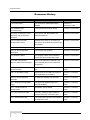
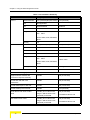
Document History
Document History
Topic
Description
Date Issued
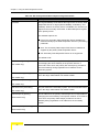
1.2.8 Connectors
The connectors' specifications were
Version 1.0
updated.
November, 2005
Commissioning description added.
Version 1.0 November
2.4 Notes on Using the Voice
Using the VG with BreezeMAX and
Version 1.0 November
Gateway (VG) in Alvarion's
BreezeACCESS VL
2.3 Installation and
Commissioning
Systems
3.2 Accessing the Web
Detailed instructions for accessing the
Version 1.0 November
Configuration Server
web server via the WAN and via the LAN
were added.
3.5.1 WAN Status Page
Bridge Status new display.
Version 1.0 November
3.6.5 VLAN Configuration
The example was updated.
Version 1.0 November
The Telephone Menu was modified to
Version 1.0 November
Example 2
3.7 Telephone Menu
include the H323 Configuration page.
3.12 Web Configuration
Some of the parameters defaults have
Server's Parameters Summary
been changed (also in their respective
Version 1.0 November
paragraphs)
2.3 Installation and
Updated for VG management via WAN
Version 1.1 February
Commissioning
only.
2006
3.6.1 VLAN Tagging Page
Default VLAN ID for LAN was removed,
Version 1.1 February
and explanations were added.
2006
An additional example was provided
Version 1.1 February
3.6.6 VLAN Configuration
Example
2006
3.7.1 SIP/H323 Configuration
The page was updated (support of
Version 1.1 February
Page
Message Waiting)
2006
3.7.1.1 Codecs and Fax
Jitter Buffer options added.
Version 1.1 February
Configuration
3.7.2 SIP Extensions Page
3.7.4 STUN Client Page
ii
2006
SIP notify messages option added, to
Version 1.1 February
keep the SIP proxy connection alive.
2006
The STUN Client submenu was added to
Version 1.1 February
the Telephone menu
2006
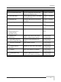
Voice Gateways System Manual
Legal Rights
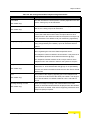
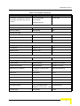
Topic
Description
Date Issued
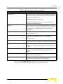
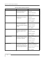
3.7.6 Line Configuration Page
The Line Configuration submenu was
Version 1.1 February
added to the Telephone menu
2006
The RTP Statistics submenu was added
Version 1.1 February
to the System menu
2006
Download option from an HTTP server
Version 1.1 February
was added.
2006
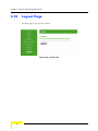
Logout option added.
Version 1.1 February
3.9.5 RTP Stats Page
3.10 Upgrade Page
3.12 Logout Page
2006
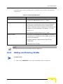
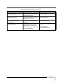
General
No H323 support
Version 1.2 August
2006
2.3 (Installation and
Login with user name and password
Version 1.2 August
2006
Commissioning) and 3.2
(Accessing the Web
Configuration Server)
2.3 Installation and
Added access to the VG via LAN (in
Version R2H276
Commissioning
addition to WAN) using the WAN IP
December 2006
3.5.1 WAN Status Page and
Broadcast Limit and Multicast Limit
Version R2H276
3.5.2 WAN Configuration Page
deleted.
December 2006
3.7.1 SIP/H323 Configuration
Default dialplan changed
Version R2H276
Page
3.7.1.1 Codecs and Fax
December 2006
Optional use of G711A/U codex enabled
Configuration
3.7.7.1 Hotline
Version R2H276
December 2006
Hotline option added to the dialplan
Version R2H276
December 2006
3.7.7.2 Adding/Removing
Automatic addition and removal of
Version R2H276
Prefixes
prefixes options added to the dialplan
December 2006
Voice Gateways System Manual
iii
Legal Rights
Legal Rights
© Copyright 2006 Alvarion Ltd. All rights reserved.
The material contained herein is proprietary, privileged, and confidential and
owned by Alvarion or its third party licensors. No disclosure thereof shall be made
to third parties without the express written permission of Alvarion Ltd.
Alvarion Ltd. reserves the right to alter the equipment specifications and
descriptions in this publication without prior notice. No part of this publication
shall be deemed to be part of any contract or warranty unless specifically
incorporated by reference into such contract or warranty.
Trade Names
Alvarion®, BreezeCOM®, WALKair®, WALKnet®, BreezeNET®, BreezeACCESS®,
BreezeMANAGE™, BreezeLINK®, BreezeCONFIG™, BreezeMAX™, AlvariSTAR™,
BreezeLITE™, AlvariCRAFT™, MGW™, eMGW™, WAVEXpress™, MicroXpress™,
WAVEXchange™, WAVEView™, GSM Network in a Box and TurboWAVE™ and/or
other products and/or services referenced here in are either registered
trademarks, trademarks or service marks of Alvarion Ltd.
All other names are or may be the trademarks of their respective owners.
Statement of Conditions
The information contained in this manual is subject to change without notice.
Alvarion Ltd. shall not be liable for errors contained herein or for incidental or
consequential damages in connection with the furnishing, performance, or use of
this manual or equipment supplied with it.
Warranties and Disclaimers
All Alvarion Ltd. ("Alvarion") products purchased from Alvarion or through any of
Alvarion's authorized resellers are subject to the following warranty and product
liability terms and conditions.
Exclusive Warranty
(a) Alvarion warrants that the Product hardware it supplies and the tangible
media on which any software is installed, under normal use and conditions, will
be free from significant defects in materials and workmanship for a period of
fourteen (14) months from the date of shipment of a given Product to Purchaser
(the "Warranty Period"). Alvarion will, at its sole option and as Purchaser's sole
remedy, repair or replace any defective Product in accordance with Alvarion'
standard R&R procedure.
iv
Voice Gateways System Manual
Legal Rights
(b) With respect to the Firmware, Alvarion warrants the correct functionality
according to the attached documentation, for a period of fourteen (14) month from
invoice date (the "Warranty Period")". During the Warranty Period, Alvarion may
release to its Customers firmware updates, which include additional performance
improvements and/or bug fixes, upon availability (the "Warranty"). Bug fixes,
temporary patches and/or workarounds may be supplied as Firmware updates.
Additional hardware, if required, to install or use Firmware updates must be
purchased by the Customer. Alvarion will be obligated to support solely the two (2)
most recent Software major releases.
ALVARION SHALL NOT BE LIABLE UNDER THIS WARRANTY IF ITS TESTING
AND EXAMINATION DISCLOSE THAT THE ALLEGED DEFECT IN THE PRODUCT
DOES NOT EXIST OR WAS CAUSED BY PURCHASER'S OR ANY THIRD
PERSON'S MISUSE, NEGLIGENCE, IMPROPER INSTALLATION OR IMPROPER
TESTING, UNAUTHORIZED ATTEMPTS TO REPAIR, OR ANY OTHER CAUSE
BEYOND THE RANGE OF THE INTENDED USE, OR BY ACCIDENT, FIRE,
LIGHTNING OR OTHER HAZARD.
Disclaimer
(a) The Software is sold on an "AS IS" basis. Alvarion, its affiliates or its licensors
MAKE NO WARRANTIES, WHATSOEVER, WHETHER EXPRESS OR IMPLIED,
WITH RESPECT TO THE SOFTWARE AND THE ACCOMPANYING
DOCUMENTATION. ALVARION SPECIFICALLY DISCLAIMS ALL IMPLIED
WARRANTIES OF MERCHANTABILITY AND FITNESS FOR A PARTICULAR
PURPOSE AND NON-INFRINGEMENT WITH RESPECT TO THE SOFTWARE.
UNITS OF PRODUCT (INCLUDING ALL THE SOFTWARE) DELIVERED TO
PURCHASER HEREUNDER ARE NOT FAULT-TOLERANT AND ARE NOT
DESIGNED, MANUFACTURED OR INTENDED FOR USE OR RESALE IN
APPLICATIONS WHERE THE FAILURE, MALFUNCTION OR INACCURACY OF
PRODUCTS CARRIES A RISK OF DEATH OR BODILY INJURY OR SEVERE
PHYSICAL OR ENVIRONMENTAL DAMAGE ("HIGH RISK ACTIVITIES"). HIGH
RISK ACTIVITIES MAY INCLUDE, BUT ARE NOT LIMITED TO, USE AS PART OF
ON-LINE CONTROL SYSTEMS IN HAZARDOUS ENVIRONMENTS REQUIRING
FAIL-SAFE PERFORMANCE, SUCH AS IN THE OPERATION OF NUCLEAR
FACILITIES, AIRCRAFT NAVIGATION OR COMMUNICATION SYSTEMS, AIR
TRAFFIC CONTROL, LIFE SUPPORT MACHINES, WEAPONS SYSTEMS OR
OTHER APPLICATIONS REPRESENTING A SIMILAR DEGREE OF POTENTIAL
HAZARD. ALVARION SPECIFICALLY DISCLAIMS ANY EXPRESS OR IMPLIED
WARRANTY OF FITNESS FOR HIGH RISK ACTIVITIES.
(b) PURCHASER'S SOLE REMEDY FOR BREACH OF THE EXPRESS
WARRANTIES ABOVE SHALL BE REPLACEMENT OR REFUND OF THE
PURCHASE PRICE AS SPECIFIED ABOVE, AT ALVARION'S OPTION. TO THE
Voice Gateways System Manual
v
Legal Rights
FULLEST EXTENT ALLOWED BY LAW, THE WARRANTIES AND REMEDIES SET
FORTH IN THIS AGREEMENT ARE EXCLUSIVE AND IN LIEU OF ALL OTHER
WARRANTIES OR CONDITIONS, EXPRESS OR IMPLIED, EITHER IN FACT OR BY
OPERATION OF LAW, STATUTORY OR OTHERWISE, INCLUDING BUT NOT
LIMITED TO WARRANTIES, TERMS OR CONDITIONS OF MERCHANTABILITY,
FITNESS FOR A PARTICULAR PURPOSE, SATISFACTORY QUALITY,
CORRESPONDENCE WITH DESCRIPTION, NON-INFRINGEMENT, AND
ACCURACY OF INFORMATION GENERATED. ALL OF WHICH ARE EXPRESSLY
DISCLAIMED. ALVARION' WARRANTIES HEREIN RUN ONLY TO PURCHASER,
AND ARE NOT EXTENDED TO ANY THIRD PARTIES. ALVARION NEITHER
ASSUMES NOR AUTHORIZES ANY OTHER PERSON TO ASSUME FOR IT ANY
OTHER LIABILITY IN CONNECTION WITH THE SALE, INSTALLATION,
MAINTENANCE OR USE OF ITS PRODUCTS.
Limitation of Liability
(a) ALVARION SHALL NOT BE LIABLE TO THE PURCHASER OR TO ANY THIRD
PARTY, FOR ANY LOSS OF PROFITS, LOSS OF USE, INTERRUPTION OF
BUSINESS OR FOR ANY INDIRECT, SPECIAL, INCIDENTAL, PUNITIVE OR
CONSEQUENTIAL DAMAGES OF ANY KIND, WHETHER ARISING UNDER
BREACH OF CONTRACT, TORT (INCLUDING NEGLIGENCE), STRICT LIABILITY
OR OTHERWISE AND WHETHER BASED ON THIS AGREEMENT OR
OTHERWISE, EVEN IF ADVISED OF THE POSSIBILITY OF SUCH DAMAGES.
(b) TO THE EXTENT PERMITTED BY APPLICABLE LAW, IN NO EVENT SHALL
THE LIABILITY FOR DAMAGES HEREUNDER OF ALVARION OR ITS EMPLOYEES
OR AGENTS EXCEED THE PURCHASE PRICE PAID FOR THE PRODUCT BY
PURCHASER, NOR SHALL THE AGGREGATE LIABILITY FOR DAMAGES TO ALL
PARTIES REGARDING ANY PRODUCT EXCEED THE PURCHASE PRICE PAID
FOR THAT PRODUCT BY THAT PARTY (EXCEPT IN THE CASE OF A BREACH OF
A PARTY'S CONFIDENTIALITY OBLIGATIONS).
Disposal of Electronic and Electrical Waste
Disposal of Electronic and Electrical Waste
Pursuant to the WEEE EU Directive electronic and electrical waste must not be disposed of with
unsorted waste. Please contact your local recycling authority for disposal of this product.
vi
Voice Gateways System Manual
Legal Rights
Important Notice
This user manual is delivered subject to the following conditions and restrictions:
This manual contains proprietary information belonging to Alvarion Ltd. Such
information is supplied solely for the purpose of assisting properly authorized
users of the respective Alvarion products.
No part of its contents may be used for any other purpose, disclosed to any
person or firm or reproduced by any means, electronic and mechanical,
without the express prior written permission of Alvarion Ltd.
The text and graphics are for the purpose of illustration and reference only.
The specifications on which they are based are subject to change without
notice.
The software described in this document is furnished under a license. The
software may be used or copied only in accordance with the terms of that
license.
Information in this document is subject to change without notice. Corporate
and individual names and data used in examples herein are fictitious unless
otherwise noted.
Alvarion Ltd. reserves the right to alter the equipment specifications and
descriptions in this publication without prior notice. No part of this
publication shall be deemed to be part of any contract or warranty unless
specifically incorporated by reference into such contract or warranty.
The information contained herein is merely descriptive in nature, and does not
constitute an offer for the sale of the product described herein.
Any changes or modifications of equipment, including opening of the
equipment not expressly approved by Alvarion Ltd. will void equipment
warranty and any repair thereafter shall be charged for. It could also void the
user's authority to operate the equipment.
Voice Gateways System Manual
vii
About This Manual
This manual describes Alvarion's Voice Gateway units and how to install, operate
and manage them. Version R2H276 supports SIP only.
This manual is intended for technicians responsible for installing, setting up and
operating the Voice Gateway, and for system administrators responsible for
managing the Voice Gateways.
This manual contains the following chapters and appendices:
Chapter 1 - System Description: Describes the Voice Gateway and its
functionality.
Chapter 2 - Installation: Describes how to install the Voice Gateway and
connect it to the SU and to the user's equipment.
Chapter 3 - Using the Web Configuration Server: Describes how to use the
Web Configuration Server for configuring parameters and checking system
status.
Appendix A - Internal Class 5 Services: Describes the internal Class-5 services
that are supported by the Gateway.
Appendix B - Default Telephony Parameters: Describe the default values for
some telephony parameters, including signals/tones parameters, CID
parameters and line impedance.
Glossary: Provides definitions of various terms used in the manual.
Contents
Chapter 1 - System Description
1.1 Introducing the Voice Gateway.................................................................................... 2
1.2 Specifications ................................................................................................................ 3
1.2.1 Telephony and Fax Services................................................................................ 3
1.2.2 Security ................................................................................................................ 3
1.2.3 Voice Quality ........................................................................................................ 4
1.2.4 Configuration and Management........................................................................... 4
1.2.5 Bridge Functionality.............................................................................................. 4
1.2.6 Mechanical ........................................................................................................... 5
1.2.7 Electrical............................................................................................................... 5
1.2.8 Connectors........................................................................................................... 5
1.2.9 Regulatory Standards Compliance ...................................................................... 6
1.2.10 Environmental ...................................................................................................... 6
Chapter 2 - Installation
2.1 Installation Requirements ............................................................................................ 8
2.1.1 Packing List.......................................................................................................... 8
2.1.2 Additional Installation Requirements.................................................................... 8
2.2 Front and Rear Panel Components ............................................................................. 9
2.2.1 Connectors........................................................................................................... 9
2.2.2 Reset to Factory Default Configuration ................................................................ 9
2.2.3 LEDs .................................................................................................................. 10
2.3 Installation and Commissioning ................................................................................ 11
2.4 Notes on Using the Voice Gateways in Alvarion's Systems ................................... 14
Contents
2.4.1 BreezeMAX System (Version 1.5 and higher) ................................................... 14
2.4.2 BreezeACCESS VL System (Version 3.1) ......................................................... 14
Chapter 3 - Using the Web Configuration Server
3.1 Introduction to the Web Configuration Server ......................................................... 16
3.2 Accessing the Web Configuration Server................................................................. 17
3.3 Using the Web Configuration Server......................................................................... 18
3.4 Home Menu - Product info Page ................................................................................ 20
3.5 WAN Menu ................................................................................................................... 22
3.5.1 WAN Status Page .............................................................................................. 22
3.5.2 WAN Configuration Page ................................................................................... 24
3.6 VLAN Tagging Menu ................................................................................................... 26
3.6.1 VLAN Tagging Page .......................................................................................... 26
3.6.2 Adding and Deleting VLANs............................................................................... 27
3.6.3 VoIP VLAN Configuration Page ......................................................................... 29
3.6.4 VLAN Configuration Example 1 ......................................................................... 30
3.6.5 VLAN Configuration Example 2 ......................................................................... 32
3.6.6 VLAN Configuration Example 3 ......................................................................... 35
3.7 Telephone Menu .......................................................................................................... 38
3.7.1 SIP/H323 Configuration Page ............................................................................ 39
3.7.2 SIP Extensions Page ......................................................................................... 48
3.7.3 NAT Traversal Configuration Page (SIP Only)................................................... 50
3.7.4 STUN Client Configuration Page (SIP only)....................................................... 51
3.7.5 ToS Page ........................................................................................................... 52
3.7.6 Line Configuration Page..................................................................................... 53
xii
Voice Gateways System Manual
Contents
3.7.7 Dial Plan Schemes............................................................................................. 54
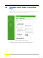
3.8 BW Reservation - DRAP Configuration Page ........................................................... 58
3.9 System Menu ............................................................................................................... 62
3.9.1 Set Security Password Page.............................................................................. 62
3.9.2 Localization Page............................................................................................... 64
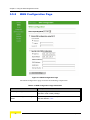
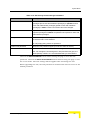
3.9.3 SNMP Configuration Page ................................................................................. 65
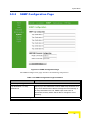
3.9.4 Service Access Configuration Page................................................................... 66
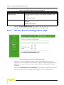
3.9.5 RTP Statistics Page ........................................................................................... 67
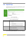
3.10Upgrade Page.............................................................................................................. 68
3.10.1 Downloader Result Codes (hexadecimal).......................................................... 69
3.11Restart Page................................................................................................................ 71
3.12Logout Page ................................................................................................................72
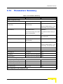
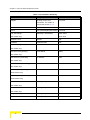
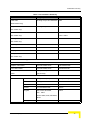
3.13Parameters Summary................................................................................................. 73
Appendix A - Internal Class 5 Services
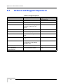
A.1 Actions and Keypad Sequences................................................................................ 80
A.2 Using the Class 5 Services......................................................................................... 81
A.2.1 Call Waiting ........................................................................................................ 81
A.2.2 Call Inquiry ......................................................................................................... 81
A.2.3 Call Alteration..................................................................................................... 81
A.2.4 Call Drop ............................................................................................................ 81
A.2.5 3-Party Conference 1 ......................................................................................... 82
A.2.6 3-Party Conference 2 ......................................................................................... 82
A.2.7 Call Waiting Indication Tone .............................................................................. 82
A.2.8 Call Forward....................................................................................................... 83
Appendix B - Default Telephony Parameters
Glossary
Voice Gateways System Manual
xiii
1
Chapter 1 - System Description
In This Chapter:
“Introducing the Voice Gateway” on page 1-2
“Specifications” on page 1-3
Chapter 1 - System Description
1.1
Introducing the Voice Gateway
Alvarion's Voice Gateway enables operators and service providers using Alvarion's
Broadband Wireless Access system to provide subscribers with a number of
broadband services transparently. The Voice Gateway enables bundling services
such as telephony (Voice over IP) and high speed Internet to end-users.
IP-telephony services are supported for standard analog phones or G3 fax
machines. The VG-1D1V has a single POTS interface, and the VG-1D2V has two
POTS interfaces. The Voice Gateways are available with either H.323 or SIP
standard, and support both narrow (compressed) and wide band (uncompressed)
speech codecs, silence suppression with comfort noise, line echo cancellation and
regional telephone parameters. Class 5 services such call waiting and 3-party
conference call are also supported.
Up to 3 telephones can be connected in series to each telephone port. Daisy
chaining of Voice Gateways enables the service provider to offer certain end users,
for example small offices, additional telephone numbers.
The Voice Gateway also supports Internet access or any other Ethernet based
services. The unit can be installed behind a router/NAT due to NAT traversal
support allowing signaling as well as voice packets to correctly reach Softswitch or
Gatekeeper for bi-directional call initiations. The Gateway can handle up to 16
simultaneous VLANs, enabling the operator to offer different services to different
end users behind the unit.
These Gateways incorporate the proprietary DRAP (Dynamic Resources Allocation
Protocol) protocol for automatic registration and allocation of resource. DRAP is a
protocol based on IP/UDP between the Gateway and a DRAP server (e.g. the
BreezeMAX base station). The protocol provides an auto-discovery mechanism for
the Gateway, so no specific configuration is required and the Gateway can
automatically locate and register with the DRAP server. The protocol uses a few
simple messages enabling a Voice Gateway to request resources when calls are
made, and the DRAP server to dynamically allocate them.
The Voice Gateways are designed for remote management and supervision using
either the built-in internal web server or SNMP.
The Voice Gateways are easily updated and upgraded as they support remote
software and configuration file download.
2
System Description
Specifications
1.2
Specifications
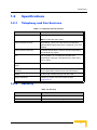
1.2.1
Telephony and Fax Services
Table 1-1: Telephony and Fax Services
Item
Description
VoIP Standard
H323 model: H323v2/4
SIP model: SIP (RFC 3261)
Internal Class 5 Services
Call Waiting, 3-party call, call hold and call alteration,
differentiated ringing tones (refer to Appendix A for more
details)
External Class 5 Services
Activation/deactivation of class 5 services supported by
the IP-telephony system
Fax
G3 compliant V.17 14.4 Kbps fax reception and
transmission using the T.38 standard (or in-band using
G.711 codec)
Calling Number Identification
FSK, DTMF
(CNI)
3rd party initiated pause and
External rerouting of media stream during speech, e.g.
rerouting
for pre-paid calling card and record announcement
DTMF
In-band and out-band using H.245 and H.225
Regional Settings
Telephony signals, tones and cadences (see
Appendix B)
1.2.2
Security
Table 1-2: Security
Item
Description
VLAN
Support IEEE 802.1Q with up to 16 VLAN IDs
Authentication
Per call authentication and registration
Voice Gateways System Manual
3
Chapter 1 - System Description
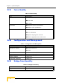
1.2.3
Voice Quality
Table 1-3: Voice Quality
Item
Description
Voice Codecs
G.711 Ulaw
G.711 Alaw
G.729ab
IEEE 802.1p layer-2 prioritization
Prioritization
DiffServ layer-3 prioritization
Adaptive jitter buffer
General
Echo cancellation
Speech sampling rate: 10-60 ms
Silence suppression with comfort noise
1.2.4
Configuration and Management
Table 1-4: Configuration and Management
Item
Description
Management Options
Internal Web Server
SNMP
SNMP Agents
SNMPv1 clientMIB II (RFC 1213), Private MIB
Plug & Play Functionality
DHCP, including support messages option 60, 61, 43
Software Upgrade
Using TFTP
Configuration Download
Using TFTP
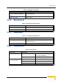
1.2.5
Bridge Functionality
Table 1-5: Bridge Functionality
Item
Description
Supported Ethernet Devices
Up to 32 MAC addresses
4
System Description
Specifications
Table 1-5: Bridge Functionality
Item
Description
Unknown address Forwarding
Forward Unknown
Policy
Bridge Aging Time
1.2.6
180 seconds
Mechanical
Table 1-6: Mechanical Specifications
Item
Details
Dimensions (W x D x H)
17.6 x 11 x 2.8 cm
Weight
230g
1.2.7
Electrical
Table 1-7: Electrical Specifications
Item
Details
Power Input
12 VDC from an external power supply, 100-240 VAC,
50-60 Hz, 2A max.
Power Consumption
1.2.8
10.5 W max.
Connectors
Table 1-8: Connectors
Connection
Description
LAN
Type
10/100Base-TX (RJ-45)Ethernet
connection: MDI/MDIX
PHONE
(1 - 2 in VG-1D2V)
Voice Gateways System Manual
Cable Length
max 100 m.
Type
RJ-11
Number of Phones (REN)
Up to 5
Cable Length
Max. 500 m
5
Chapter 1 - System Description
Table 1-8: Connectors
Connection
Description
WAN
Type
10/100Base-TX (RJ-45)
Ethernet Connection to SU-IDU/hub:
Straight
Cable Length
12 VDC
1.2.9
max 100 m.
Standard DC power jack to external power supply
Regulatory Standards Compliance
Table 1-9: Standards Compliance
Type
Standard
EMC
Low Voltage Directive (LVD) 73/23/EEC
Electromagnetic Compatibility Directive (EMC)
89/336/EEG
Safety
IEC 60950
CSA C22.2 No. 950-95/UL 1950
AS/NZS 3260
Emission
EN 55022:1998 Class B
EN 61000-3-2:1995
Harmonics; EN 61000-3-3:1995
Flicker; FCC part 15 (1998) Class B
AS/NZS 3548 (1995)
Immunity
EN 55024:1998
1.2.10 Environmental
Table 1-10: Environmental Specifications
Item
Details
Operating temperature
0 o C to 50 o C
Operating humidity
10%-95% RH non condensing
6
System Description
2
Chapter 2 - Installation
In This Chapter:
“Installation Requirements” on page 2-8
“Front and Rear Panel Components” on page 2-9
“Installation and Commissioning” on page 2-11
“Notes on Using the Voice Gateways in Alvarion's Systems” on page 2-14
Chapter 2 - Installation
2.1
Installation Requirements
2.1.1
Packing List
Voice Gateway with one (VG-1D1V) or two (VG-1D2V) Phone Ports
Power supply with a DC connecting cable
Mains power cable
2.1.2
Additional Installation Requirements
A straight Ethernet cable for connecting the WAN port to the SU-IDU
An Ethernet cable for connecting to the user's data equipment (straight for
connecting to a PC, crossed for connecting to a hub/switch)
Standard phone cable(s) with RJ-11 connectors.
Mains plug adapter (if the power plug on the supplied mains power cable does
not fit local power outlets).
Portable PC with an Ethernet card and an Ethernet cable for configuring the
Voice Gateway parameters using a web browser.
8
Installation
Front and Rear Panel Components
2.2
Front and Rear Panel Components
2.2.1
Connectors
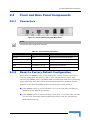
Figure 2-1: Voice Gateway VG-1D2V Back Panel
NOTE
The VG-1D1V has a single Phone connector.
Table 2-1: Voice Gateway Connectors
Name
Connector
Functionality
Phone 1
RJ-11
Connections to the user's telephones
Phone 2 (VG-1D2V only)
RJ-11
Connections to the user's telephones
LAN
10/100Base-T (RJ-45)
Connection to the user's data equipment
WAN
10/100Base-T (RJ-45)
Connection to the SU-IDU
12 VDC
DC power jack
Connection to power supply
2.2.2
Reset to Factory Default Configuration
Press down the RESET button on the back of the unit for at least 5 seconds to
reset all configurable parameters back to their original default values. After
releasing the RESET button, the PWR, WAN and LAN LEDs blink twice, indicating
proper operation. The affect on the selected IP parameters acquisition method
depends on the time the RESET button is held in the pressed position:
If the RESET button is pressed down for 5 to 10 seconds: The unit will use
DHCP to get the WAN IP parameters.
If the RESET button is pressed down for more than 10 seconds: The unit will
use the static (manually defined) WAN IP parameters (IP 192.168.254.254
Mask 255.255.255.0).
Voice Gateways System Manual
9
Chapter 2 - Installation
For more details on configuration of DHCP and static IP parameters, refer to
Section 3.5.2.
2.2.3
LEDs
Figure 2-2: VG-1D2V Front Panel
NOTE
The VG-1D1V has a single Phone LED.
Table 2-2: Voice Gateway LEDs
Name
Symbol
Phone 1
Description
Functionality
Phone service
indication
Off -Phone line does not get IP telephony
services
On - Phone line is connected to the
IP-telephony system
Phone 2
(VG-1D2V only)
Phone service
indication
Off -Phone line does not get IP telephony
services
On - Phone line is connected to the
IP-telephony system
LAN
LAN port status
indication
Off - Ethernet Link not detected
On - Ethernet link connected, no activity
Blinking - Ethernet link activity
WAN
WAN port status
indication
Off - Ethernet link not detected
On - Ethernet link connected, no activity
Blinking - Ethernet link activity
POWER
PWR
Power Indication
Off - unit is not powered or power failed
Green - power OK
10
Installation
Installation and Commissioning
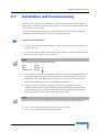
2.3
Installation and Commissioning
The unit can be placed on a desktop or a shelf. The location should be selected
taking into account the necessary connections to mains power, SU-IDU and user's
data/telephony equipment.
It is assumed that installation and commissioning of the SU has already been
completed and that the SU is connected to the Base Station.
To install the Voice Gateway:
1
Connect the DC power cable of power supply to the 12 VDC jack on the rear
panel of the unit.
2
Connect the mains power cable to the power supply. Connect the other end of
the mains power cable to the AC mains.
NOTE
The color codes of the power cable are as follows:
Brown
Phase
~
Blue
Neutral
0
Yellow/Green
Ground
3
After power up, all front panel LEDs bilnk once, and then the PWR, WAN and
LAN LEDs bilnk twice, indicating that the unit operates properly. Then the
PWR LED is lit. Other LEDs may also be lit, according to the status of the
WAN, LAN and Phone ports, as described in Section 2.2.3.
4
Connect a PC to the WAN or LAN port using a crossed Ethernet cable.
Configure the PC with a static IP address 192.168.254.2 and subnet mask
255.255.255.0. (The IP address of the WAN port for management purposes
only is 192.168.254.254 and netmask 255.255.255.0)
NOTE
The VG can be accessed via the WAN or LAN port using the WAN IP address.
5
Open a web browser and connect to the unit by entering
http://192.168.254.254. in the address field.
Voice Gateways System Manual
11
Chapter 2 - Installation
6
If the Web Configuration Server is password protected, you will be prompted to
enter your username and password in order to log in to the system. The
default username is operator and the default password is installer. See
Chapter 3 for details on using the Web Configuration Server.
7
Configure the necessary parameters according to instructions supplied by the
system administrator. The mandatory parameters that must be configured
properly are:
Enable DRAP (in BW Reservation page) only if DRAP is supported by the
wireless system (currently DRAP is supported by BreezeMAX equipment
with SW version 1.5 or higher and BreezeACCESS VL with SW version 4.0).
Uncheck if DRAP is not used.
LAN/WAN VLAN Tagged Port Membership parameters (VLAN page) and
VoIP VLAN parameters (VoIP VLAN Configuration page).
Telephony parameters (per line) in the SIP Configuration/H323 Telephone
page: Telephone Line Enable/Disable, primary SIP Server/H323 Gate
Keeper parameters, User Name and Password (SIP model), Telephone
Number, Telephone domain name (SIP model). Certain H323 Gatekeepers
require configuration of a unique H323 Alias.
WAN IP parameters (WAN Configuration page): For operation as a DHCP
client, check the Obtain WAN Configuration dynamically. For static IP
configuration, check the Specify fixed WAN configuration option and
specify the IP Address, Subnet Mask and Default Gateway.
8
Restart the unit from the Restart page.
9
If VLANs are configured for management, you will lose management from the
PC, unless the packets are tagged from the PC towards the Voice Gateway. To
resume management capabilities, return to factory defaults (see
Section 2.2.2).
10 Disconnect the PC used for configuration.
11 Use a straight Ethernet cable to connect the WAN port on the rear panel of the
unit to the Ethernet port of the SU-IDU. The length of the indoor-to-outdoor
Ethernet cable should not exceed 90 meters. The length of the Ethernet cable
connecting the indoor unit to the user's equipment, together with the length of
the Indoor-to-Outdoor cable, should not exceed 100 meters.
12 Connect the data equipment using a 10/100 Base-T Ethernet cable to the LAN
port. The length of the Ethernet cable should not exceed 100m. Use a straight
cable for connecting to a PC, or a crossed cable for connecting to a
hub/switch).
12
Installation
Installation and Commissioning
13 Use standard telephone cord(s) with RJ-11 termination to connect the
telephony equipment to the unit.
14 Verify proper operation using the LED indicators (see Table 2-2).
15 To verify data connectivity, from the end-user's PC or from a portable PC
connected to the unit, try to connect to the Internet or to ping another unit in
the network.
16 Verify proper telephony operation by establishing a call to another telephone
(for each enabled line).
Voice Gateways System Manual
13
Chapter 2 - Installation
2.4
Notes on Using the Voice Gateways in
Alvarion's Systems
2.4.1
BreezeMAX System (Version 1.5 and higher)
Access the Monitor program of the SU from a PC connected to the LAN port of
the Gateway. The SU's Monitor program uses the fixed IP address
192.168.254.251 with the subnet mask 255.255.255.0. The PC used for
accessing the Monitor program should be configured to belong to the same
subnet. It is recommended to set the PC's IP address to 192.168.254.250,
which is the default TFTP Server IP address in the Monitor (required for
downloading SW versions and for downloading/uploading configuration files).
Information about the DRAP-enabled Gateways that are connected to each SU
can be viewed in the Base Station's Monitor program (in the Voice/Networking
Gateways option of the Configuration menu for a selected SU). The displayed
information includes Gateway's type, IP Address, and the VLAN ID used for
management.
In general, the same VLAN should be configured in the Voice Gateway for
Management (Default VLAN ID) and Voice (RTP and Signaling) as the Voice
Gateway uses one IP address for two VLANs and the default router in the
backbone cannot operate in this mode.
To support the required quality of service when DRAP is used, provision the
correct VoIP Service. If DRAP is not used, provision an L2 Service with a CG
connection (refer to the BreezeMAX System Manual for details).
2.4.2
BreezeACCESS VL System (Version 3.1)
To access the Monitor program of the SU from a PC connected to the LAN port
of the Gateway, the WAN port must be configured with static IP address that is
in the same subnet as the IP Address of the SU, and subnet mask
255.255.255.0 (the default IP address is 10.0.0.1 with a Subnet Mask
255.255.255.0). The PC used for accessing the Monitor program should be
configured to belong to the same subnet.
Configure the Traffic Prioritization parameters in both the SU and the AU to
ensure high priority for RTP traffic. Refer to the BreezeACCESS VL System
Manual for details.
14
Installation
3
Chapter 3 - Using the Web Configuration
Server
In This Chapter:
“Introduction to the Web Configuration Server” on page 3-16
“Accessing the Web Configuration Server” on page 3-17
“Using the Web Configuration Server” on page 3-18
“Home Menu - Product info Page” on page 3-20
“WAN Menu” on page 3-22
“VLAN Tagging Menu” on page 3-26
“Telephone Menu” on page 3-38
“BW Reservation - DRAP Configuration Page” on page 3-58
“System Menu” on page 3-62
“Upgrade Page” on page 3-68
“Restart Page” on page 3-71
“Logout Page” on page 3-72
“Parameters Summary” on page 3-73
Chapter 3 - Using the Web Configuration Server
3.1
Introduction to the Web Configuration
Server
The Voice Gateway can be configured using the following methods:
The Web Configuration Server
An .ini-file loaded into the unit from a TFTP-server or automatically
downloaded using DHCP option 43.
This document describes the configuration using the Web Configuration Server.
16
Operation
Accessing the Web Configuration Server
3.2
Accessing the Web Configuration Server
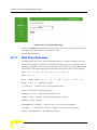
To manage the unit you must have prior knowledge of its WAN IP Address. Follow
the steps below to access the Web Configuration Server:
1
Open a web browser.
2
Enter the WAN IP address of the unit in the Address field of the browser and
click Enter. E.g., http://192.168.254.254 (default).
3
If the Web Configuration Server is password protected, you will be prompted
to enter your user name and password in order to login to the system.
To login with operator privileges (full access and read/write privileges), the
default user name is operator and the default password is installer.
To login with administrator privileges (partial access and read/write
privileges), the default user name is admin. No password is required.
4
The Web Configuration Server main view appears on the screen.
Voice Gateways System Manual
17
Chapter 3 - Using the Web Configuration Server
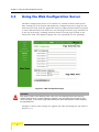
3.3
Using the Web Configuration Server
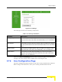
The Web Configuration Server view consists of a number of menu links (to the
left). Clicking on each of them will display the configuration/status page for the
selected menu item, with the applicable content (configurable parameters/options
or status information) in the main area. Several pages include a page selection bar
at the top of the page, enabling selection between several pages related to the
same menu item. The displayed pages may vary depending on user privileges.
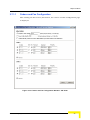
Figure 3-1: Web Configuration Page
CAUTION
Many pages include a "Save Settings" button. Click on the Save Settings button before selecting
another page/menu item, or before quitting the application. The Save Settings functionality in many
cases is per page - if you leave the page without clicking the Save Settings button, all the changes in
the page will be lost.
Changes to most of the settings are applied only after restarting the unit (refer to
Section 3.11).
18
Operation
Using the Web Configuration Server
CAUTION
There is no control that the entered values are valid or have the correct format or range. If invalid
values are entered, access to the unit may be lost and in that case a factory default procedure must be
performed. Refer to Section 2.2.2 for information about how to reset the Voice Gateway to factory
default parameters.
Voice Gateways System Manual
19
Chapter 3 - Using the Web Configuration Server
3.4
Home Menu - Product info Page
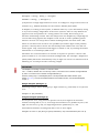
The Product Info page provides general information on the Voice Gateway.
Figure 3-2: Product Info Page
The Product Info page includes the following components:
Table 3-1: Product Info Page Parameters
Parameter
Description
Name
The unit's model
Mac address
The MAC address of the unit
Serial Number
The serial number of the unit
Product number
Not Used
Product revision
The hardware revision
Production week
Production date in the format <yy>w<ww>. <yy> is the year (two last
digits) and ww is the week (two digits).
Default configuration
The unit's configuration
Downloader revision
The revision of the SW download SW module.
20
Operation
Home Menu - Product info Page
Table 3-1: Product Info Page Parameters
Parameter
Description
Reported download status
The status of the SW download operation. For more details refer to
Section 3.10.1.
Main software revision
The unit's main SW version
Operator defaults revision
The custom .ini file (if exists)
In any case of contact with Alvarion Customer Service, include the Default
configuration, Downloader revision, Main software revision and Operator defaults
revision (.ini file) if exists.
Voice Gateways System Manual
21
Chapter 3 - Using the Web Configuration Server
3.5
WAN Menu
The WAN menu page includes settings related to the operation and functionality
on the WAN (network) side of the unit.
NOTE
Be careful when setting these parameters to avoid conflicts in the network.
The WAN page selection bar includes the following options:
WAN Status (Section 3.5.1)
WAN Configuration (Section 3.5.2)
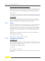
3.5.1
WAN Status Page
Figure 3-3: WAN Status Page
The WAN Status page includes the following components:
22
Operation
WAN Menu
Table 3-2: WAN Status Page Parameters
Parameter
Description
Interface Status
Enabled
The administrative status of the WAN port: Yes or No. In the current
version the administrative status cannot be disabled.
Service
The configured operation mode. In current version it is always
Bridged.
Bridge Status
The method of handling packets with an unknown destination address.
In the current version it is always Forwarding.
Protocol
The protocol used for data transmission: In the current version it is
always Ethernet.
Interface Status
The operational status of the WAN port: Up or Down.
Network Settings
Dynamic IP Assignment
The method of configuring IP Address, Subnet Mask, Default Gateway
and DNS Address, as defined in the WAN Configuration page:
Yes (via DHCP): the parameters are obtained from a DHCP server.
No: the parameters are configured manually
IP Address
The IP address of the unit
MAC Address
The MAC address of the unit
Subnet Mask
The IP Subnet Mask
Default Gateway
The Default Gateway address
DNS Address
IP DNS Server address
Domain Name
The Domain Name as defined in the WAN Configuration page
VLAN Tag
The VLAN ID tag defined for management traffic
Priority Tag
The Priority tag defined for management traffic
Click on the Update button to refresh the display.
Voice Gateways System Manual
23
Chapter 3 - Using the Web Configuration Server
3.5.2
WAN Configuration Page
Figure 3-4: WAN Configuration Page
The WAN Configuration page includes the following components:
Table 3-3: WAN Configuration Page Parameters
Parameter
Description
Device Operating Mode
The operating mode of the unit. In current version the
operation mode is always Bridge.
Obtain WAN configuration using
Select this option to obtain IP parameters from a DHCP server.
DHCP
See also Section 2.2.2.
24
Operation
WAN Menu
Table 3-3: WAN Configuration Page Parameters
Parameter
Description
Client identity
Applicable only if the "Obtain WAN configuration dynamically"
option is selected. The method used for identifying the client
(Option 61). The options are:
Standard: The unit's MAC address
Custom: An identification string of up to 25 characters. The
default is null (an empty string)
Vendor ID
Applicable only if the "Obtain WAN configuration dynamically"
option is selected. The Vendor ID (Option 60). A string of up to
25 characters. The default used by the unit is VoIP (not
displayed).
Specify static WAN configuration
Select this option to configure the IP parameters manually.
See also Section 2.2.2.
IP Address
Applicable only if the "Specify fixed WAN configuration" option
is selected. The IP address of the unit. The default is
192.168.254.254
Subnet Mask
Applicable only if the "Specify fixed WAN configuration" option
is selected. The IP Subnet Mask. The default is 255.255.255.0
Default Gateway
Applicable only if the "Specify fixed WAN configuration" option
is selected. The Default Gateway address. The default is none
(empty)
DNS Address
Applicable only if the "Specify fixed WAN configuration" option
is selected. IP DNS Server address. The default is none
(empty)
Host Name
The Host name for clients. A string of up to 25 characters. The
default is null (an empty string).
Domain Name
The Domain Name for client resolution. A string of up to 25
characters. The default is null (an empty string).
Click on the Save WAN Settings button before leaving the page to save the new
settings. The new settings will be applied after restarting the unit.
Voice Gateways System Manual
25
Chapter 3 - Using the Web Configuration Server
3.6
VLAN Tagging Menu
The VLAN Tagging page selection bar includes the following options:
VLAN Tagging (Section 3.6.1)
VoIP VLAN Configuration (Section 3.6.3)
3.6.1
VLAN Tagging Page
The Voice Gateway supports 802.1Q VLAN standard, allowing IEEE 802 Local
Area Networks (LANs) of all types to be connected together with Media Access
Control (MAC) Bridges, as specified in ISO/IEC 15802-3. This standard defines
the operation of Virtual LAN (VLAN) Bridges that permit the definition, operation
and administration of Virtual LAN topologies within a bridged LAN infrastructure.
Figure 3-5: VLAN Tagging Page
26
Operation
VLAN Tagging Menu
The VLAN page enables defining up to 16 VLANs, and it includes the following
components:
Table 3-4: VLAN Page Parameters
Parameter
Description
Tagged Port Membership
A table displaying the defined VLANs. For details on
modifying the table refer to Section 3.6.2 below.
Untagged VLAN ID
The VLAN ID that is defined for untagged data on the WAN
port (text box on the left side) and the LAN port (text box on
the right side). This parameter must be consistent with a
properly configured VLAN in the tagged port membership. For
examples on VLAN configuration, see Section 3.6.4 and
Section 3.6.5.
The range for both parameters is from 1 to 4094.
Default VLAN ID
The text box on the left side is for the WAN port. This is the
VLAN defined for management frames (SNMP, HTTP, TFTP)
arriving on the WAN port.
The DRAP packets are tagged with the default VLAN
configuration.
The range is from 1 to 4094.
NOTE
Management of the unit can only be done from the WAN port.
3.6.2
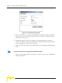
Adding and Deleting VLANs
To add a VLAN:
1
Click on the Add VLAN button. The VLAN Editor (Add) is displayed:
Voice Gateways System Manual
27
Chapter 3 - Using the Web Configuration Server
Figure 3-6: VLAN Editor (Add VLAN)
2
Enter the VLAN ID (1 to 4094), VLAN NAME (A descriptive string of printable
characters. Do not use special characters such as space or comma), and the
VLAN priority tag (0 to 7).
3
If applicable packets need to be tagged on the WAN/LAN port, check the
relevant Yes option. Otherwise check the No option. Note that only one VLAN
can be untagged on each port (or on both).
4
Click OK. The newly added entry will be added to the Tagged Port Membership
table.
To delete a VLAN from the Tagged Port Membership table:
1
Click on the row ID number of the entry you wish to remove. The VLAN Editor
(Delete) is displayed:
28
Operation
VLAN Tagging Menu
Figure 3-7: VLAN Editor (Delete VLAN)
2
Click on the Delete button. The entry will be removed from the Tagged Port
Membership table.
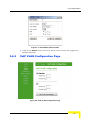
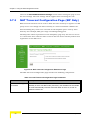
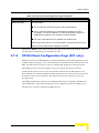
3.6.3
VoIP VLAN Configuration Page
Figure 3-8: VoIP VLAN Configuration Page
Voice Gateways System Manual
29
Chapter 3 - Using the Web Configuration Server
The VoIP VLAN configuration page enables defining the following parameters:
Table 3-5: VoIP VLAN Configuration Page Parameters
Parameter
Description
Call Signaling
VLAN Tag
The VLAN ID tag for VoIP call signaling packets. If not set, the
Default VLAN ID set for WAN (in the VLAN Tagging page) will
also apply for VOIP.
Priority Tag
The Priority tag for VoIP call signaling packets. If not set, the
priority tag defined for the Management VLAN in the Tagged Port
Membership (in the VLAN Tagging page), will also apply for
VOIP.
RTP
VLAN Tag
The VLAN ID tag for RTP and RTCP packets. If not set, the
Default VLAN ID set for WAN (in the VLAN Tagging page) will
also apply for VOIP.
Priority Tag
The Priority tag for RTP and RTCP packets. If not set, the priority
tag defined for the Management VLAN in the Tagged Port
Membership (in the VLAN Tagging page), will also apply for
VOIP.
Typically, the same VLAN is used for management, call signaling and RTP. In this
case, the same VLAN and Priority Tags should be configured for management
(Default VLAN on WAN port in the VLAN Tagging page), Call Signaling and RTP.
However, the Voice Gateway supports separation of VLANs and allows defining 3
different VLANs for management, call signaling and RTP traffic (this may require a
proper router). Different Priority tags for management, call signaling and RTP can
be configured. The Priority tag for management is defined in the Priority field of
the management VLAN ID (configured in the Tagged Port Membership table).
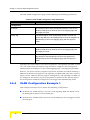
3.6.4
VLAN Configuration Example 1
This example describes how to define the following configuration:
VLAN ID 100, VLAN Priority 7 for Voice (call signaling, RTP and RTCP) and 5
for Management packets on the WAN port.
VLAN ID 200, VLAN Priority 0 for data on the WAN port and untagged to/from
the LAN port.
30
Operation
VLAN Tagging Menu
VLAN200
(Data)
Untagged
VLAN100
(Voice &
Management)
POTS
Figure 3-9: VLAN Configuration Example 1
1
In the VLAN page, click Add VLAN to open the VLAN Editor.
2
In the VLAN Editor, enter the follwing for Voice and Management VLAN:
VLAN ID: 100
VLAN NAME: Voice&Mng
VLAN Priority: 5
WAN: Yes
LAN: No
3
Click OK to add the VLAN to the Tagged Port Membership table.
4
Enter the VLAN ID for Voice and Management (100) in the field Default VLAN
ID on WAN port, and click Save.
5
In the Page Selection bar, click on VoIP VLAN Configuration to open the VoIP
VLAN Configuration page. Enter 100 in the VLAN Tag fields for both Call
Signaling and RTP. Enter 7 in the Priority Tag field for both Call Signaling and
RTP. Click Save VoIP VLAN Settings. Go back to the VLAN Tagging page.
6
In the VLAN page, click Add VLAN to open the VLAN Editor to configure the
data VLAN.
Voice Gateways System Manual
31
Chapter 3 - Using the Web Configuration Server
7
In the VLAN Editor, enter the follwing for data:
VLAN ID: 200 (an arbitrary selection-a VLAN ID is required for defining the
untagged data. This VLAN tag is only used internally in the unit)
VLAN NAME: Data
VLAN Priority: 0
WAN: Yes
LAN: Yes
8
Click OK to add the VLAN to the Tagged Port Membership table.
9
Enter the VLAN ID for untagged data (200) in the fields Untagged VLAN ID on
LAN port and click Save.
10 Restart the unit to apply the changes.
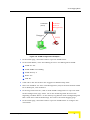
3.6.5
VLAN Configuration Example 2
This example describes how to define the following configuration:
Two daisy-chained Voice Gateways: VG-1 and VG-2.
VLAN ID 100, VLAN Priority 7 for Voice (call signaling, RTP and RTCP) and
Management packets on the WAN port.
VLAN ID 200, VLAN Priority 4 for data on WAN port (VG-1)
No VLAN for data on the LAN port (VG-2).
32
Operation
VLAN Tagging Menu
VLAN 200
VLAN100
VG-1
POTS
VG-2
Untagged
Figure 3-10: VLAN Configuration Example 2
3.6.5.1
VG-1 Configuration
1
In the VLAN page, click Add VLAN to open the VLAN Editor.
2
In the VLAN Editor, enter the follwing for Voice and Management VLAN:
VLAN ID: 100
VLAN NAME: Voice&Mng
VLAN Priority: 7
WAN: Yes
LAN: Yes
3
Click OK to add the VLAN to the Tagged Port Membership table.
4
Enter the VLAN ID for Voice and Management (100) in the fields Default VLAN
ID on WAN port, and click Save.
5
In the Page Selection bar, click on VoIP VLAN Configuration to open the VoIP
VLAN Configuration page. Enter 100 in the VLAN Tag fields for both Call
Voice Gateways System Manual
33
Chapter 3 - Using the Web Configuration Server
Signaling and RTP. Enter 7 in the Priority Tag field for both Call Signaling and
RTP. Click Save VoIP VLAN Settings. Go back to the VLAN Tagging page.
6
In the VLAN page, click Add VLAN to open the VLAN Editor.
7
In the VLAN Editor, enter the follwing for Data VLAN:
VLAN ID: 200
VLAN NAME: Data
VLAN Priority: 4
WAN: Yes
LAN: Yes
8
Click OK to add the VLAN to the Tagged Port Membership table.
9
Enter the VLAN ID for untagged data (200) in the field Untagged VLAN ID on
LAN port and click Save.
10 Restart the unit to apply the changes.
3.6.5.2
VG-2 Configuration
1
In the VLAN page, click Add VLAN to open the VLAN Editor.
2
In the VLAN Editor, enter the follwing for Voice and Management VLAN:
VLAN ID: 100
VLAN NAME: Voice&Mng
VLAN Priority: 7
WAN: Yes
LAN: No
34
3
Click OK to add the VLAN to the Tagged Port Membership table.
4
Enter the VLAN ID for Voice and Management (100) in the field Default VLAN
ID on WAN port, and click Save.
5
In the Page Selection bar, click on VoIP VLAN Configuration to open the VoIP
VLAN Configuration page. Enter 100 in the VLAN Tag fields for both Call
Signaling and RTP. Enter 7 in the Priority Tag field for both Call Signaling and
RTP. Click Save VoIP VLAN Settings. Go back to the VLAN Tagging page.
6
In the VLAN page, click Add VLAN to open the VLAN Editor.
7
In the VLAN Editor, enter the follwing for untagged data:
Operation
VLAN Tagging Menu
VLAN ID: 300 (an arbitrary selection-a VLAN ID is required for defining the
untagged data. This VLAN tag is only used internally in the unit)
VLAN NAME: Untagged
VLAN Priority: 0
WAN: Yes
LAN: Yes
8
Click OK to add the VLAN to the Tagged Port Membership table.
9
Enter the VLAN ID for untagged data (300) in the fields Untagged VLAN ID on
LAN port and Untagged VLAN ID on WAN port, and click Save.
10 Restart the unit to apply the changes.
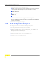
3.6.6
VLAN Configuration Example 3
This example describes how to define the following configuration:
One Voice Gateway.
VLAN ID 60, VLAN Priority 6 for Voice (call signaling, RTP and RTCP) and
Management packets on the WAN port.
No VLAN for data packets on WAN and LAN ports
No VLAN
VLAN 60
VG
Untagged
POTS
Figure 3-11: VLAN Configuration Example 3
Voice Gateways System Manual
35
Chapter 3 - Using the Web Configuration Server
3.6.6.1
Method 1
1
In the VLAN page, click Add VLAN to open the VLAN Editor.
2
In the VLAN Editor, enter the follwing for Voice and Management VLAN:
VLAN ID: 60
VLAN NAME: Voice&Mng
VLAN Priority: 6
WAN: Yes
LAN: No
3
Click OK to add the VLAN to the Tagged Port Membership table.
4
Enter the VLAN ID for Voice and Management (60) in the field Default VLAN
ID on WAN port, and click Save.
5
In the Page Selection bar, click on VoIP VLAN Configuration to open the VoIP
VLAN Configuration page. Enter 60 in the VLAN Tag fields for both Call
Signaling and RTP. Enter 6 in the Priority Tag field for both Call Signaling and
RTP. Click Save VoIP VLAN Settings. Go back to the VLAN Tagging page.
6
In the VLAN page, click Add VLAN to open the VLAN Editor.
7
In the VLAN Editor, enter the follwing for untagged data:
VLAN ID: 90 (an arbitrary selection-a VLAN ID is required for defining the
untagged data. This VLAN tag is only used internally in the unit)
VLAN NAME: Untagged
VLAN Priority: 0
WAN: Yes
LAN: Yes
8
Click OK to add the VLAN to the Tagged Port Membership table.
9
Enter the VLAN ID for untagged data (90) in the fields Untagged VLAN ID on
LAN port and Untagged VLAN ID on WAN port, and click Save.
10 Restart the unit to apply the changes.
3.6.6.2
36
Method 2
1
In the VLAN page, click Add VLAN to open the VLAN Editor.
2
In the VLAN Editor, enter the follwing for Voice and Management VLAN:
Operation
VLAN Tagging Menu
VLAN ID: 60
VLAN NAME: Voice&Mng
VLAN Priority: 6
WAN: Yes
LAN: No
3
Click OK to add the VLAN to the Tagged Port Membership table.
4
Enter the VLAN ID for Voice and Management (60) in the field Default VLAN
ID on WAN port, and click Save.
5
In the Page Selection bar, click on VoIP VLAN Configuration to open the VoIP
VLAN Configuration page. Enter 60 in the VLAN Tag fields for both Call
Signaling and RTP. Enter 6 in the Priority Tag field for both Call Signaling and
RTP. Click Save VoIP VLAN Settings. Go back to the VLAN Tagging page.
6
There is no need to define VLAN in the Port Tag Membership table or in the
Untagged WAN and LAN fields. Untagged packets will pass through LAN to
WAN and WAN to LAN.
7
Restart the unit to apply the changes.
Voice Gateways System Manual
37
Chapter 3 - Using the Web Configuration Server
3.7
Telephone Menu
In the SIP model, the Telephone page selection bar includes the following options:
SIP (Section 3.7.1)
SIP Extensions (Section 3.7.2)
NAT (Section 3.7.3)
STUN Client (Section 3.7.4)
ToS (Section 3.7.5)
In the H323 model, the Telephone page selection bar includes the following
options:
H323 (Section 3.7.1)
ToS (Section 3.7.5)
38
Operation
Telephone Menu
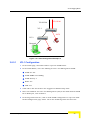
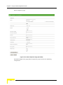
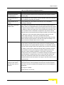
3.7.1
SIP/H323 Configuration Page
SIP Configuration page:
Figure 3-12: SIP Configuration Page (VG-1D2V)
Voice Gateways System Manual
39
Chapter 3 - Using the Web Configuration Server
H323 Telephone page:
Figure 3-13: H323 Telephone Page (VG-1D2V)
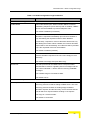
The SIP Configuration page/H323 Telephone pages include the following
components:
40
Operation
Telephone Menu
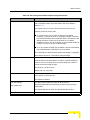
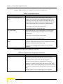
Table 3-6: SIP Configuration/H323 Telephone Page Parameters
Parameter
Description
Dialplan
The Dialplan parameter defines how the Voice Gateway decides
that a complete number has been dialed. See more details in
Section 3.7.7.
The default value is xx.T|xx.#, which means that each of the
following schemes can be used:
xx.T: Dial timeout. Any number of digits may be dialed.
Following T seconds in which no new digit is dialed, a decision
is reached that dialing was completed and the unit will send the
dialing sequence received up to this time as a complete
telephone number. This is necessary since the whole telephone
number is sent at once and not digit by digit.
xx.#: Any number of digits may be dialed. A decision that dialing
was completed will be reached once # is pressed.
The combination of both schemes means that dialing is completed
either after a timeout of T seconds or after pressing #.
Dial timeout
The timeout in seconds for the dial timeout dialplan. The number of
seconds that the unit waits before it sends a complete telephone
number. This is necessary since the whole telephone number is
sent at once and not digit by digit.
The range is 1 to 60 seconds
Default value is 4 seconds.
Use #
Use # as a quick dial function. To send the # along with the number
to the server, uncheck the box.
The default is enabled.
RTP Port Range
(SIP model only)
The start and end UDP port-range for RTP protocol.
Recommended values for Start and End ports are in the range
1030-65535.
The default Start port is 8000. The default End port is 8015.
Telephone line
Voice Gateways System Manual
Switch the telephone line On or Off. The default is Off.
41
Chapter 3 - Using the Web Configuration Server
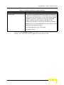
Table 3-6: SIP Configuration/H323 Telephone Page Parameters
Parameter
Description
HA mode
The High Availability mode defines the support of a secondary Gate
Keeper/SIP Server for high system availability, redundancy, and
scalability. When a secondary server is available, the unit will try to
register to the secondary server after 10 failed attempts to register
to the primary server.
The available options are:
Fixed: The secondary Gate Keeper/SIP Server IP address is
defined manually by the Gate Keeper/SIP Server IP (secondary)
parameter.
Auto: The secondary Gate Keeper /SIP Server IP address is
supplied by the primary Gate Keeper/SIP Server.
Off: Secondary Gate Keeper/SIP Server is not supported.
The default is Off.
SIP Server IP (primary)
(SIP model only)
The IP address for the primary SIP server/proxy who is responsible
for managing the Voice Gateway in the specific network. If
HA-mode is set to Auto, the primary SIP server/proxy provides to
the Voice Gateway during registration an IP address for the
secondary system.
SIP Server Port (primary)
(SIP model only)
SIP Server IP (secondary)
The port used for the primary system. The recommended values
are in the range 1030-65536. The default is 5060.
The IP address of the secondary SIP server/proxy.
(SIP model only)
SIP Server Port (secondary)
(SIP model only)
Gate Keeper IP (primary)
(H323 model only)
The port used for the secondary system. The recommended values
are in the range 1030-65536. The default is 5060.
The IP address for the primary Gate Keeper who is responsible for
managing the Voice Gateway in the specific network. If HA-mode is
set to Auto, the primary Gate Keeper provides to the Voice
Gateway during registration an IP address for the secondary
system.
Gate Keeper IP (secondary)
The IP address of the secondary Gate Keeper.
(H323 model only)
42
Operation
Telephone Menu
Table 3-6: SIP Configuration/H323 Telephone Page Parameters
Parameter
Description
User Name
The SIP user Name. Format (name or number) depends on the SIP
(SIP model only)
Password
(SIP model only)
H323 Alias
server. A string of up to 25 characters.
The SIP user Password. Format (name or number) depends on the
SIP server. A string of up to 25 characters.
The unit's name used when registering the unit at the Gate Keeper.
If used, the H323 alias must be set to a unique value for each
telephone line in the network in order for the system to accept it. Up
to 25 characters. The default is null (not used during registration).
Outgoing Display name
The name to be displayed on the caller ID display of a receiving
party (if supported by the network). Up to 25 characters with no
spaces.
Telephone number
The telephone number of the specific telephone line to be used
when registering the unit at the Gate keeper/SIP Server.
The telephone number is limited to 25 characters. It may also be an
e-mail address (limited to 25 characters before the @ sign).
The Telephone number must be set to a unique value for each
telephone line in the network in order for the system to accept it.
Telephone domain name
(SIP model only)
The domain-name. The Telephone domain name is limited to 25
characters, i.e. 25 characters after the @-sign. If not specified by
the user, the same information as defined in the SIP Server IP field
will be used.
Port
(SIP model only)
The number of the outgoing signaling port on the telephone line.
Line1 and Line 2 cannot have the same port number. The range is
from 1030 to 65535. The default is 5060 for Line 1 and 5061 for
Line 2.
Message Waiting Account
(SIP model only)
When a message is waiting in the network-based voice mail
system, a discontinuous dial tone will be played when the handset
goes off hook. To enable, a SIP server supporting Interactive Voice
Response (IVR) is required.
Voice Gateways System Manual
43
Chapter 3 - Using the Web Configuration Server
Table 3-6: SIP Configuration/H323 Telephone Page Parameters
Parameter
Description
Incoming CLIP
The Calling Line Identity Presentation (Caller ID) option for the
telephone line. If On is selected, the Caller ID information of a
calling party in incoming calls will be displayed on a caller ID
display attached to the telephone line.
Caller ID can be restricted permanently using a customized .ini file.
The default is Off.
Keepalive Timeout (seconds)
The interval of waiting for acknowledgement message from the
server. If Keep-alive timeout is sent from the network, it will override
the setting in the Voice Gateway. The interval for sending
Keep-alive registration messages from the Gateway is half the
configured value (600 seconds with the default timeout of 1200
seconds).
In case of registration problem, try changing the value to 1800
seconds.
The range is from 10 to 65535 seconds.
The default is 1200 seconds.
Ring signal [0 - 9]
The Ring signal parameter provides a selection of 10 different ring
patterns (0-9) that the unit can use.
The default is 0.
Transport
Configure whether signaling shall use UDP or TCP. The default is
(SIP model only)
Preferred codecs
UDP.
Displays the currently supported codecs, according to the defined
priorities.
Click the Set Codecs/Fax button to change codecs
settings/priorities.
NOTE: Click Save before clicking the Set Codecs/Fax button.
Otherwise, all configuration changes in the Telephone page will be
lost.
Click on the Save button before leaving the page to save the new settings. The new
settings will be applied after restarting the unit.
Click the Set Codecs/Fax button to change codecs settings/priorities as
described in the following section.
44
Operation
Telephone Menu
3.7.1.1
Codecs and Fax Configuration
After clicking the Set Codecs/Fax button, the Codecs and Fax Configuration page
is displayed.
Figure 3-14: Codecs and Fax Configuration Window - VG-1D2V
Voice Gateways System Manual
45
Chapter 3 - Using the Web Configuration Server
The jitter buffer options are common to both lines (if applicable):
Table 3-7: Jitter Buffer Options
Parameter
Description
Adaptive Jitter Buffer Maximum
The Voice Gateway uses a Jitter Buffer to eliminate jitter
Delay
effects. The size of the buffer changes dynamically to reflect
actual jitter conditions. The Adaptive Jitter Buffer Maximum
Delay defines the maximum size that is available for the jitter
buffer (the larger the size, the greater the potential delay).
The range is from 100 to 300 milliseconds.
The default duration is 100 milliseconds.
Fixed Jitter Buffer
When using fax only, it is recommended to use a fixed jitter
buffer. The fixed jitter buffer may affect voice conversation
performance.
The range is from 100 to 300 milliseconds.
The default duration is 40 milliseconds.
Automatically switch to Fixed Jitter
Select this option in order to use both fax and voice. The Voice
Buffer
Gateway automatically switches to the configured Fixed Jitter
Buffer upon detecting a fax/modem tone.
Faxes can be transmitted when Codec G.711 or T38 are
selected.
The following settings are available for each line:
Table 3-8: Codecs and Fax Configuration Parameters
Parameter
Description
Codec
The Codec check boxes identify which codecs are used.
By default all three codecs are selected (checked).
NOTE: G 729 with Annex A is implemented in the Voice
Gateway. It enables communication with devices using either
G729 with Annex A or G729 with Annex A and Annex B. It is not
possible to communicate with devices using G729 with Annex B
only.
For each Codec in use, the following can be configured:
46
Operation
Telephone Menu
Table 3-8: Codecs and Fax Configuration Parameters
Parameter
Description
SS
The SS (Silent Suppression) option for outgoing calls. When the
SS option is enabled, silence intervals are identified and only
relevant information is transmitted, using less bandwidth than
during voice activity intervals. This allows for a better overall
utilization of the available bandwidth. It is possible to enable
Silent Suppression with G729 codec. Silent Suppression is not
applicable when using the G711 codecs.
The default (G729) is SS disabled.
EC
The EC (Echo Cancellation) option, defines whether to activate
the echo cancellation mechanism for improved voice quality. EC
is not used during Fax (T.38) transmissions.
The default is enabled.
Packet
The packet size in milliseconds.
The range is from 10 to 150 milliseconds.
The default is 30 ms for G729 and 20 ms for G711A and G711U.
Keypad
The "Keypad" field indicated which transmission method to be
used for user input DTMF signaling (i.e. phone banking). "None"
means in-band, which should be used with G.711 only.
For SIP model the options are None, RFC2833 and SIP INFO.
RFC2833 and SIP INFO should be used primarily with G.729
but could also be used with G.711. The default is None for G711
codecs and RFC2833 for G729.
For H323 model the options are H225, H245, RFC2833 and
None. The default is None for G711 codecs and H225 for G729.
Priority
The Priority parameter defines the relative priorities to be offered
during capabilities' exchange. If only G711A and G711U are
used, the permitted priorities are 1 and 2.
If all 3 codecs are used, the permitted priorities are 1, 2 and 3.
Voice codec negotiation/priority is always performed between 2
end-points and depending on which side initiated the
negotiation.
The default is Priority 1 to G711A, Priority 2 to G711U.
Voice Gateways System Manual
47
Chapter 3 - Using the Web Configuration Server
Table 3-8: Codecs and Fax Configuration Parameters
Parameter
Description
T38 Fax
The T38 check box indicates for each line whether to support
the T38 Fax protocol.
The default is checked (T38 Fax supported).
Click on the Save button before leaving the page to save the new settings. The new
settings will be applied after restarting the unit.
3.7.2
SIP Extensions Page
Figure 3-15: SIP Extensions Page
The SIP Extensions page includes the following components:
Table 3-9: SIP Extensions Page Parameters
Parameter
Description
Support PRACK method
The PRACK request plays the same role as ACK, but for provisional
with provisional response
responses. PRACK is a normal SIP message, like BYE. As such, its own
reliability
reliability is ensured hop-by-hop through each stateful proxy. Also like BYE,
but unlike ACK, PRACK has its own response. If this were not the case, the
PRACK message could not traverse proxy servers compliant to RFC 2543.
For more details refer to RFC 3262: Reliability of Provisional Responses in
the Session Initiation Protocol (SIP).
48
Operation
Telephone Menu
Table 3-9: SIP Extensions Page Parameters
Parameter
Description
Encode SIP URI with
User=Phone will be inserted in the Contact field of SIP uniform resource
user parameters
identifier (URI).
Encode default port in
Include default port in SIP uniform resource identifier (URI) even though it
SIP URI
is not mandatory according to standard.
Include default port in
Include default port in the INVITE even though it is not mandatory
INVITE
according to standard
Send INVITE with timer
If the called user agents (UA) or the SIP Proxy Server (SPS) requires a
header value
session timer for a requested session and the calling UA does not include
the Session-Expires header in the INVITE message, then the called UA or
the SPS may reject the request with a 487-request failure message. If the
use of a session timer is desirable but optional for the session and the
calling UA does not include the Session-Expires header in the INVITE then
the called UA or SPS may add a Session-Expires header to the next
session setup message. In this case, the SPS shall add the
Session-Expires header to the INVITE message and the called UA shall
add the Session-Expires header to the 200 OK response message. The
range for the timer header value is from 1 to 999.
SIP Session timer value
The SIP Session Timer Support feature adds the capability to periodically
refresh Session Initiation Protocol (SIP) sessions by sending repeated
INVITE requests. The repeated INVITE requests, or re-INVITEs, are sent
during an active call leg to allow user agents (UA) or proxies to determine
the status of a SIP session. Without this keep alive mechanism, proxies
that remember incoming and outgoing requests (stateful proxies) may
continue to retain call state needlessly. If a UA fails to send a BYE
message at the end of a session or if the BYE message is lost because of
network problems, a stateful proxy does not know that the session has
ended. The re-INVITES ensure that active sessions stay active and
completed sessions are terminated. The range for the timer value is from 1
to 999 seconds.
Use NOTIFY message to
The gateway will send a SIP NOTIFY message to the SIP proxy at the
keep alive the session
configured interval. These messages can keep the connection with SIP
with SIP proxy every X
proxy alive, as well as the NAT port mapping when the Voice Gateway is
seconds
behind NAT.
The range is: 0-99999
Default interval: 15 seconds
Voice Gateways System Manual
49
Chapter 3 - Using the Web Configuration Server
Click on the Save SIP Extensions Settings button before leaving the page to save
the new settings. The new settings will be applied after restarting the unit.
3.7.3
NAT Traversal Configuration Page (SIP Only)
NAT Traversal function can be used to allow the Voice Gateway to register to a SIP
proxy server even though the Voice Gateway is connected behind a NAT device.
Port forwarding may need to be activated for all telephone ports used by Voice
Gateway: For example, RTP port range and SIP signaling ports.
The Keep alive timeout parameter in the Telephony page may also need to be set
to a value lower than 1200 seconds to ensure that the Voice Gateway will not lose
registration to the SIP server.
Figure 3-16: NAT Traversal Configuration Extensions Page
The NAT Traversal Configuration page includes the following components:
Table 3-10: NAT Traversal Configuration Page Parameters
Parameter
Description
External NAT-mapped
The IP address that the NAT device uses on the WAN side. If the Voice
IP Address
Gateway is set to Auto NAT mode (see below), the IP address of the outside
IP will be automatically inserted. If the NAT Mode is set to On, a NAT IP
Address must be set.
50
Operation
Telephone Menu
Table 3-10: NAT Traversal Configuration Page Parameters
Parameter
Description
Static NAT Mode:
The NAT mode:
On = Enable NAT Traversal function using manual setting.
Auto = Enter NAT mode if any of the following conditions is met:a.
IP-address = Private IP address b. "received" parameter in INVITE or
REGISTER IP-address is not equal to internal IP address.
Off = NAT Traversal function is disabled.The default is Off.
When using a NAT device, it is recommended to set this parameter to ON
and to enter the External NAT-mapped IP Address.
Click on the Save button before leaving the page to save the new settings. The new
settings will be applied after restarting the unit.
3.7.4
STUN Client Configuration Page (SIP only)
Simple Traversal of UDP (STUN) is a method of NAT traversal through UDP, based
on RFC 3489. For proper voice conversations in networks based on more than one
NAT, the NAT devices must be able to transfer RTP packets in both directions.
The STUN protocol uses the default server port 3478. The Voice Gateway
communicates with a server over the internet. Based on the RTP packets, the
Server knows the number of NATs behind which the Voice Gateway is located, the
IP address of the Voice Gateway, and which of the Voice Gateway's ports are
actually used.
The STUN application supports the following NAT Types: FullCone, FullRestrict,
and PortRestrict. The Voice Gateway does not support symmetrical NAT as it is
not meant to traverse symmetrical NAT devices.
Voice Gateways System Manual
51
Chapter 3 - Using the Web Configuration Server
Figure 3-17: STUN Client Configuration Page
The STUN Client page includes the following components:
Table 3-11: STUN Client Configuration Page Parameters
Parameter
Description
STUN Client Mode
Switch the STUN Client mode on or off. When on, turn off the
Static NAT Traversal mode.
STUN Server Address (IP or Domain)
The IP address or Domain of the STUN server.
STUN Server Port
The port used by the STUN Server.
The default is port 3478.
Click on the Save STUN Client Settings button before leaving the page to save
the new settings. The new settings will be applied after restarting the unit.
STUN enabled cannot operate with NAT traversal enabled. In any case, the Voice
Gateway receives the external IP and the port information using the STUN.
3.7.5
ToS Page
Outgoing packets from the Voice Gateway can be marked with DSCP (DiffServ
Code Point) values. The ToS page enables defining the 8-bits ToS field in the IP
header for different packet types. Diffserv use the first 6 out of these 8 bits.
For more information about DiffServ Code Points please refer to RFC2474.
52
Operation
Telephone Menu
Figure 3-18: ToS Page
The ToS page includes the following components:
Table 3-12: ToS Page Parameters
Parameter
Description
Call signaling Packets
ToS marking for call signaling packets. Enter a number in the range 0 to
255 (The first 6 bits is the value of the DSCP field) or null. The default is
0.
RTP Packets
ToS marking for RTP and RTCP packets. Enter a number in the range 0
to 255 (The first 6 bits is the value of the DSCP field) or null. The default
is 0.
SNMP Packets
ToS marking for SNMP packets. Enter a number in the range 0 to 255
(The first 6 bits is the value of the DSCP field) or null. The default is 0.
Default setting
ToS marking for other types of packets (e.g. HTTP, TFTP). Enter a
number in the range 0 to 255 (The first 6 bits is the value of the DSCP
field) or null. The default is 0.
Click on the Save ToS Settings button before leaving the page to save the new
settings. The new settings will be applied after restarting the unit.
3.7.6
Line Configuration Page
The Line Configuration page enables to select the country standard for Caller ID.
When using a caller ID device, select your country/standard from the list.
Voice Gateways System Manual
53
Chapter 3 - Using the Web Configuration Server
Figure 3-19: Line Configuration Page
Click on the Save button before leaving the page to save the new settings. The new
settings will be applied after restarting the unit.
The default is Sweden.
3.7.7
Dial Plan Schemes
A dialplan gives the unit a map to determine when a complete number has been
entered and should be passed to the gatekeeper/SIP server for resolution into an
IP address. Dialplans are expressed using the same syntax as used by MGCP NCS
specification. The following notation describes the formal syntax of the dialplan:
Digit ::= "0" | "1" | "2" | "3" | "4" | "5" | "6" | "7" | "8" | "9"
Timer ::= "T" | "t"
Letter ::= Digit | Timer | "#" | "*" | "A" | "a" | "B" | "b" | "C" | "c" | "D" | "d"
Range ::= "X" | "x" -- matches any digit
| "[" Letters "]" -- matches any of the specified letters
Letters::= Subrange | Subrange Letters
Subrange::= Letter -- matches the specified letter
| Digit "-" Digit -- matches any digit between first and last
Position::= Letter | Range
StringElement::= Position -- matches any occurrence of the position
| Position "." -- matches an arbitrary number of occurrences including 0
String ::= StringElement | StringElement String
54
Operation
Telephone Menu
StringList::= String | String "|" StringList
DialPlan::= String | "(" StringList ")"
[0-9] denotes a single digit between 0 and 9. To configure a range of more than 10
numbers (e.g., 800xxx-819xxx) use the scheme: 80xxxx|81[0-9]xxx.
A dialplan, according to this syntax, is defined either by a (case insensitive) string
or by a list of strings. Regardless of the above syntax a timer is only allowed if it
appears in the last position in a string (12T3 is not valid). Each string is an
alternate numbering scheme. The unit will process the dialplan by comparing the
current dial string against the dialplan. If the result is under-qualified (partial
matches at least one entry) then it will do nothing further but wait until a full
match is reached. If the result is over-qualified (no further digits could possibly
produce a match) then it aborts the dial attempt and notifies end-user with an
audio signal. Only a full match will trigger to initiate a call, by sending the dialed
information to a Gatekeeper/SIP server.
The Timer T is activated when it is all that is required to produce a match. The
period of timer T is 4 seconds as default (configurable). For example a dialplan of
(xxxT|xxxxx) will match immediately if any 5 digits are entered. It will also match
following a 4 second pause after entering 3 digits.
IMPORTANT
The dialplan is according to section 2.1.5 of RFC 3435.
The “.” notation, denotes zero or more keys. That is, x.# means none or at least one digit followed
by # and x.T means none or at least one digit followed by T.
However, having only T in the dialplan (where x is null) activates the Hotline function (see
Section 3.7.7.1). To avoid unwanted activation of the hotline function, use the default dialplan,
xx.#|xx.T.
Simple dialplan (Example 1):
Following example allows dialing any 7-digit number (e.g. 5551234) or an operator
on 0.
Dialplan is: (0T|xxxxxxx)
Complex dialplan (Example 2):
Local operator on 0, long distance operator on 00, four digit local extension
number starting with 3,4 or 5, seven digit local numbers are prefixed by an 8, two
digit star services (e.g. 69), ten digit long distance prefixed by 91, and
international numbers starting with 9011+one or more digits.
Dialplan for this is: (0T|00T|[3-5]xxx|8xxxxxxx|*xx|91xxxxxxxxxx|9011xx.T)
Voice Gateways System Manual
55
Chapter 3 - Using the Web Configuration Server
Using supplemental external services (Example 3):
When a soft switch or a SIP server/gatekeeper exists in the network and the user
would like to use class 5 services which are not internal to the Voice Gateway e.g.,
*xy#, *xy*abcd#, #xy#, etc., the VG dialplan should be configured as follows:
[*#][0-9*][0-9*].#
Note that when VG internal class 5 services are enabled (default) in addition to the
above dialplan, the internal class 5 activation codes remain valid. See Appendix A.
Call completion
Call completion means allowing user to skip the timer period T after finished
dialing, by ending number sequence with '#' (no other character is valid for this
feature). A valid dialplan to accomplish this would be: (xx.#|xx.T)
3.7.7.1
Hotline
The hotline function allows a predetermined number to be called automatically by
waiting T seconds (which can also be configured) without pressing any keys.
The hotline function can also be used to receive tones from the Local Exchange.
This is achieved by leaving the number in the hotline dialplan empty. Additional
modifications may be required, in which case, contact Customer Support for
assistance.
The hotline feature is activated by specifying "T" (time-out) in the dialplan (by
default, T is set to 4 seconds).
For example: (xx.#|xx.T|<:1234>T)
The number 1234 will be dialed after T seconds.
3.7.7.2
Adding/Removing Prefixes
For outgoing calls
VG can add a pre-defined prefix to a dialed number via the dialplan and send the
number with the added prefix to the server. The prefix can automatically replace a
dialed digit using the following notation:
"<'dialed substring':'transmitted-string'>"
For example:
Set the dialplan to "<8:1860>xxx"
When dialing 8123, the digit 8 is replaced with 1860, and the actual number sent
is 1860123.
56
Operation
Telephone Menu
In ethereal trace, the "To" field in SIP INVITE is "1860123"
For incoming calls
VG can remove a prefix in the dialplan and show the number without the prefix on
the phone display. Use the following notation:
"<'replacement string':'received-string'>"
For example:
Set the dialplan to "<8:1860>xxx"
When a number with the 1860 prefix is received (e.g., "1860123"), the prefix 1860
is replaced with the digit 8 and the number displayed is 8123.
Voice Gateways System Manual
57
Chapter 3 - Using the Web Configuration Server
3.8
BW Reservation - DRAP Configuration
Page
The Voice Gateway uses DRAP (Dynamic Resource Allocation Protocol) for efficient
management of bandwidth resources for telephone calls.
Figure 3-20: DRAP Configuration Page
The DRAP Configuration page includes the following components:
58
Operation
BW Reservation - DRAP Configuration Page
Table 3-13: DRAP Configuration Page Parameters
Parameter
Description
DRAP Server Settings
Enable DRAP
The Enable DRAP option defines whether DRAP is used for
establishing telephone (voice and fax) calls. If enabled, a DRAP
Server must be available to provision telephone calls.
The default is disabled (unchecked).
Enable Pre-allocation
The Enable Pre-allocation option defines whether resource
allocation is requested immediately upon off-hook condition or
only after dialing the requested number. When disabled
(unchecked), a request for resource allocation will be sent only
after dialing the number. When enabled, the resource allocation
request will be sent immediately, and a dial tone will be provided
only if the requested resources are available.
The default is enabled (checked).
DRAP Server IP Address
The IP address of the DRAP server that should serve the
resource allocation requests of the unit. Leave empty for Auto
Discovery.
The default is an empty field (Auto Discovery).
Server Port
The UDP port used for the DRAP server. The port number
indicated will be used for originating ALLOC messages and the
port number indicated +1 will be used for receiving CONFRM
messages.
The available range is from 8000 to 8200.
The default is 8171.
DRAP Protocol Options
Discovery Time
The Discovery Time is the timeout to be used when the Auto
Discovery process is used for finding a DRAP server. The Auto
Discovery process is based on sending empty broadcast
allocation requests, and the Discovery Time is the time that the
unit will wait for a response before sending a new request.
The range is 1 to 255 seconds.
The default is 10 seconds.
Voice Gateways System Manual
59
Chapter 3 - Using the Web Configuration Server
Table 3-13: DRAP Configuration Page Parameters
Parameter
Description
Acknowledge Time
The Acknowledge Time is the timeout out to be used between
allocation requests. If no confirmation is received within this time,
a new allocation request should be sent.
The range is 1 to 10 (x 100 milliseconds).
The default is 3 (300 milliseconds).
Clear Count
The Clear Count parameter indicates the number of allocation
requests (ALLOC) that can be sent without being acknowledged
before clearing all pending reservation attempts.
Note: Established reservations (existing calls) are not cleared.
The range is 1 to 10.
The default is 2.
Retry Count
The Retry Count parameter indicates the number of allocation
requests (ALLOC) that can be sent without being acknowledged
before reaching a decision that the unit should search for another
server. When this number is reached established reservations are
to be cleared (existing calls are disconnected) and auto discovery
procedure is initiated.
The range is 1 to 10.
The default is 5.
RTP Packing Ratio
The RTP Packing Ratio parameter defines the packet size to be
used until an actual call is established. It is recommended to set a
value that supports the worst-case scenario, e.g. the smallest
expected size (20 milliseconds) that results in the highest
expected number of packets per second.NOTE: The configured
RTP Packing Ratio is used by the unit until an actual call is
established. Once a call is established, the unit will use a packet
size according to the actual value being used for the call.
The available range is 10 to 100 milliseconds in multiples of 10
(10, 20, …100).
The default value is 30 milliseconds.
60
Operation
BW Reservation - DRAP Configuration Page
Table 3-13: DRAP Configuration Page Parameters
Parameter
Description
Vocoder Type
The Vocoder Type parameter defines the codec to be used until
an actual call is established. It is recommended to set a value that
supports the worst-case scenario, e.g. the codec with the highest
bandwidth requirement. Typically G711 should be configured,
except in networks where only G729 is used. NOTE: The
configured Vocoder Type is used by the unit until an actual call is
established. Once a call is established, the unit will use the actual
codec type being used for the call.
The available options are G711 and G729.
The default is G729.
Click on the Save DRAP Settings button before leaving the page to save the new
settings. The new settings will be applied after restarting the unit.
Voice Gateways System Manual
61
Chapter 3 - Using the Web Configuration Server
3.9
System Menu
The System page selection bar includes the following options:
Security (Section 3.9.1)
Localization (Section 3.9.2)
SNMP (Section 3.9.3)
Service Access (Section 3.9.4)
RTP Stats (Section 3.9.5)
3.9.1
Set Security Password Page
Figure 3-21: Set Security Password Page
The Set Security Password page includes the following components:
62
Operation
System Menu
Table 3-14: Set Security Password Page Parameters
Parameter
Description
User name
Enter the user name. The user name for users with operator
privileges (full access and read/write privileges) is operator and for
user with administrator privileges (partial access and read/write
privileges) is admin. These user names cannot be changed.
Old password
A password used previously. The default password for users with
operator privileges is installer. No password is required for users with
administrator privileges.
New password
Enter the new password. A password includes up to 20 printable
characters and is case sensitive.
A null (empty) string means no password.
Confirm new password
Enter the new password again (must be the same as above).
Access
Select the mode in which the PC can manage the IDU-DV unit. The
PC can manage the unit through the LAN (User Ethernet) port, the
WAN (Radio) or BOTH. It is recommended that you select BOTH.
Click on the Save Password button before leaving the page to save the new
password. Click on the Save Access Mode button before leaving the page to save
the access mode. The new settings will be applied after restarting the unit.
When upgrading the unit, the new password is retained and does not revert to the
default password.
Voice Gateways System Manual
63
Chapter 3 - Using the Web Configuration Server
3.9.2
Localization Page
Figure 3-22: Localization Page
The Localization page includes the following components:
Table 3-15: Localization Page Parameters
Parameter
Description
NTP Server
The IP address of the NTP-server (optional). If an IP address is
configured the NTP server usage is activated. The feature must be
activated to support FSK-based caller ID.
The default is disabled (no IP address).
Time Zone
The appropriate time zone. Use the drop-down list to change the time
zone.
Adjust clock for daylight
By checking the "Adjust clock to daylight savings" the Voice Gateway
savings
will automatically adjust to daylight saving time (set the time one hour
ahead).
The default is enabled (checked).
Click on the Save Localization Settings button before leaving the page to save
the new settings. The new settings will be applied after restarting the unit.
64
Operation
System Menu
3.9.3
SNMP Configuration Page
Figure 3-23: SNMP Configuration Page
The SNMP Configuration page includes the following components:
Table 3-16: SNMP Configuration Page Parameters
Parameter
Description
SNMP Trap Configuration
Trap Destination 1 to Trap
Specify up to 6 IP addresses to which SNMP traps should be sent.
destination 6
Only these stations will be able to manage the Voice Gateway. If
all Trap Destinations are null, SNMP traps will be sent as
broadcasts, and any station will be able to manage the Voice
Gateway.
SNMP MIB Parameter Configuration
Voice Gateways System Manual
65
Chapter 3 - Using the Web Configuration Server
Table 3-16: SNMP Configuration Page Parameters
Parameter
Description
Read Community
The read community string, up to 20 printable characters, case
sensitive.
Default string is public.
Write Community
The write community string, up to 20 printable characters, case
sensitive.
Default string is private
Click on the Save SNMP Settings button before leaving the page to save the new
settings. The new settings will be applied after restarting the unit.
3.9.4
Service Access Configuration Page
Figure 3-24: Service Access Configuration Page
The Service Access Configuration page enables to enable/disable access to
various services. Access from each of the ports (LAN or WAN) using HTTP and/or
SNMP can be either enabled or disabled. The default for all options is enabled
(checked).
Click on the Save Service Access Settings button before leaving the page to save
the new settings. The new settings will be applied after restarting the unit.
66
Operation
System Menu
3.9.5
RTP Statistics Page
The RTP Stats page enables to monitor from remote the performance of the last
call. The displayed information includes: Bandwidth (kb/s), jitter, packet loss,
and latency.
NOTE
The bandwidth relates to the payload only.
Figure 3-25: RTP Statistics Page
Voice Gateways System Manual
67
Chapter 3 - Using the Web Configuration Server
3.10
Upgrade Page
The Upgrade page enables to control the process of downloading either a software
file (with the extension .ro) or a configuration file (with the extension .ini) from a
TFTP-server or from an HTTP server.
Figure 3-26: Upgrade Page
The Upgrade page includes the following components:
Table 3-17: Upgrade Page Parameters
Parameter
Description
Upgrade Type
Auto
The Voice Gateway will automatically select the server type for
download.
TFTP
Downloads the file from the TFTP server according to the
specified host address.
HTTP
Downloads the file from the HTTP server according to the
specified URL. Not implemented in the current release.
Host
(TFTP) The IP address of the TFTP server
URL
(HTTP/Auto) Use the following syntax: IP/filename. E.g.,
192.168.254.1/DMA0027R2F201.ro
File name
The file name in the HTTP/TFTP server of the software or the
configuration .ini file. Up to 25 characters.
Click on the Start Auto/HTTP/TFTP Upgrade button to start the download
process. The downloading and installation of the new SW version or configuration
68
Operation
Upgrade Page
file is done automatically, including a restart of the unit. When the installation is
complete and the unit has restarted, the Home Product Info page will be displayed
(if not, click on the Refresh button).
The version R2H implementation of the dialplan module is fully compliant with
RFC3435. However, some previously acceptable dialplans are inconsistent with
RFC3435 operation and must therefore be changed to ensure continued operation
consistent with previous releases. You should review your dialplan to ensure that
the dial behavior will continue to be that required by your customers.
For example, the default dialplan should be changed from (x.#|x.T) to (xx.#|xx.T).
It is recommended to review your dialplan to ensure that its proper operation.
You can change the dialplan as follows:
Default dialplan
If an INI file is not used: upgrade to version R2H and then install the INI file
provided with the upgrade package.
If an INI file is used: you will be provided with an updated INI file.
Non-default dialplan
If an INI file is not used: Refer to Section 3.7.7 for information on updating
your dialplan. The dialplan can be changed via the Telephone menu, or via
option 43.
If an INI file is used: you will be provided with an updated INI file.
3.10.1 Downloader Result Codes (hexadecimal)
If something goes wrong during download or installation, you will be notified
according to the following:
0 (0x00): normal boot (no upgrade requested or needed)
bit-0 (0x01): upgrade requested or main application not valid
bit-1 (0x02): failed to download new image
bit-2 (0x04): TFTP server not defined
bit-3 (0x08): TFTP file not defined
Voice Gateways System Manual
69
Chapter 3 - Using the Web Configuration Server
bit-4 (0x10): TFTP session failed
bit-5 (0x20): CRC error in downloaded image
bit-6 (0x40): incompatible image
3.10.1.1
Examples
An attempt to download from a non-existing TFTP-server results in code 0x7 (=
0x07):
bit-2 0x04 TFTP server not defined plus…
bit-1 0x02 failed to download new image plus…
bit-0 0x01 upgrade requested or main application not valid
An attempt to download a non-existing file results in code 0xb (= 0x0b):
bit-3 0x08 TFTP file not defined plus…
bit-1 0x02 failed to download new image plus…
bit-0 0x01 upgrade requested or main application not valid
A successful download results in code 0x01
A restart without download of main application results in 0x00.
70
Operation
Restart Page
3.11
Restart Page
When settings have been inserted or altered, the Voice Gateway must be restarted
in order to apply the new settings.
Figure 3-27: Restart Page
Click the Restart button to restart the Voice Gateway.
Voice Gateways System Manual
71
Chapter 3 - Using the Web Configuration Server
3.12
Logout Page
Use this page to log out the system.
Figure 3-28: Logout Page
72
Operation
Parameters Summary
3.13
Parameters Summary
Table 3-18: Parameters Summary
Parameter
Range/Options
Default
Device Operating Mode
Only Bridge option is available
Bridge
Obtain WAN configuration
Yes (checked)/No
Default: Yes (selected)
dynamically
(unchecked)
WAN Configuration Page
Factory default (above 10 sec
HW reset): No (unchecked)
Client identity
Vendor ID
Standard/Custom
Standard
The Custom string can include
The default Custom string is
up to 25 characters
null
A string of up to 25 characters
VoIP (used by default but is
not displayed)
Specify fixed WAN configuration
Yes (checked)/No
No (unchecked)
(unchecked)
IP Address
IP address
Default: Dynamic
Factory default (above 10 sec
HW reset): 192.168.254.254
Subnet Mask
IP address
255.255.255.0
Default Gateway
IP address
Null
DNS Address
IP address
Null
Host Name
A string of up to 25 characters
Null
Domain Name
A string of up to 25 characters
Null
Call Signaling VLAN Tag
1-4094 or null
Null
Call Signaling Priority Tag
0-7 or null
Null
RTP VLAN Tag
1-4094 or null
Null
RTP Priority Tag
0-7 or null
Null
VoIP VLAN Configuration Page
SIP Configuration / H323 Telephone Page
Voice Gateways System Manual
73
Chapter 3 - Using the Web Configuration Server
Table 3-18: Parameters Summary
Parameter
Range/Options
Default
Dialplan
A string of up to 100
xx.T|xx.#
characters. For details on
format see Section 3.7.7
Dial Timeout
1-60 seconds
4 seconds
Use #
Yes (checked)/No(unchecked)
Checked
RTP Port Range
Start/Stop: 1030-65535
Start: 8000
(SIP model only)
End: 8015
Telephone Line
On/Off
Off
HA Mode
Fixed/Auto/Off
Off
SIP Server IP (primary)
IP address
Null
1030-65535
5060
IP address
Null
1030-65535
5060
IP address
Null
IP address
Null
A string of up to 25 characters
Null
A string of up to 25 characters
Null
Outgoing Display Name
A string of up to 25 characters
Null
Telephone number
A string of up to 25 characters
Null
(SIP model only)
SIP Server Port (primary)
(SIP model only)
SIP Server IP (secondary)
(SIP model only)
SIP Server Port (secondary)
(SIP model only)
Gate Keeper IP (primary)
(H323 model only)
Gate Keeper IP (secondary)
(H323 model only)
User Name
(SIP model only)
Password
(SIP model only)
74
Operation
Parameters Summary
Table 3-18: Parameters Summary
Parameter
Range/Options
Default
H323 Alias
A string of up to 25 characters
Null
A string of up to 25 characters
Null
1030-65535
Line 1: 5060
(H323 model only)
Telephone domain name
(SIP model only)
Port
(SIP model only)
Line 2: 5061
Message Waiting Account
Null
(SIP model only)
Incoming CLIP
On/Off
Off
Keepalive timeout
10-65535 seconds
1200 seconds
Ring signal
0-9
0
Transport
UDP/TCP
UDP
Adaptive Jitter Buffer
100-300 milliseconds
100 milliseconds
Fixed Jitter Buffer
100-300 milliseconds
40 milliseconds
Automatically switch to Fixed Jitter
Yes (checked)/No
Unchecked
Buffer
(unchecked)
(SIP model only)
Codecs and Fax Configuration
Jitter Buffer:
Codec:
G711A
Select/Deselect
Yes (checked)/No(unchecked)
SS
Not applicable
EC
Enable/Disable
Enabled
Packet
10-150 milliseconds
20 ms
Keypad
SIP: None, RFC2833,
None
SIP
Yes (checked)
INFO
H323: H225, H245, RFC2833,
None
Priority
Voice Gateways System Manual
1-3
1
75
Chapter 3 - Using the Web Configuration Server
Table 3-18: Parameters Summary
Parameter
G711U
Range/Options
Default
Select/Deselect
Yes (checked)/No(unchecked)
Yes (checked)
SS
Not applicable
EC
Enable/Disable
Enabled
Packet
10-150 milliseconds
20 ms
Keypad
SIP: None, RFC2833,
None
SIP
INFO
H323: H225, H245, RFC2833,
None
G729
Priority
1-3
2
Select/Deselect
Yes (checked)/No(unchecked)
Yes (checked)
SS
Enable/Disable
Disabled
EC
Enable/Disable
Enabled
Packet
10-150 milliseconds
30 ms
Keypad
SIP: None, RFC2833,
SIP: RFC2833
SIP
INFO
H323: H225
H323: H225, H245, RFC2833,
None
Priority
T38 Fax
1-3
Not Applicable
Enable/Disable
Enable
SIP Extensions Page (SIP model only)
Support PRACK method with
Yes/No
No (unchecked)
Yes/No
No (unchecked)
Encode default port in SIP URI
Yes/No
No (unchecked)
Include default port in INVITE
Yes/No
Yes (checked)
Send INVITE with timer header
Yes/No, plus a value in the
No (unchecked)
value
range 1-999 seconds if Yes
provisional response reliability
Encode SIP URI with user
parameters
(checked) is selected.
SIP Session timer value
Yes/No, plus a value in the
range 1-999 seconds if Yes
(checked) is selected.
76
The default value is null
No (unchecked)
The default value is null
Operation
Parameters Summary
Table 3-18: Parameters Summary
Parameter
Range/Options
Default
Use NOTIFY message to keep alive
Yes (checked)/No
15 seconds
the session with SIP proxy every X
(unchecked)
seconds
0-99999 seconds
NAT Traversal Configuration Page (SIP model only)
External NAT-mapped IP Address
IP address
Null
Static NAT Mode
On/Auto/Off
Off
STUN Client Mode
On/Off
Off
STUN Server Address
IP address/Domain
Null
STUN Server Port
1-65534
3478
Call signaling Packets
0-255 or null
192
RTP Packets
0-255 or null
160
SNMP Packets
0-255 or null
0
Default setting
0-255 or null
0
A list
Sweden
Enable DRAP
Enable/Disable
Disable (unchecked)
Enable Pre-allocation
Enable/Disable
Enable (checked)
DRAP Server IP Address
IP address or null for auto
Null (auto discovery)
STUN Client Page
ToS Page
Line Configuration Page
CLIP Standard
DRAP Configuration Page
discovery
Server Port
8000-8200
8171
Discovery Time
1-255 seconds
10 seconds
Acknowledge Time
1 to 10 (x 100 milliseconds)
3 (300 milliseconds)
Clear Count
1-10
2
Retry Count
1-10
5
RTP Packing Ratio
10 to 100 milliseconds in
30 milliseconds
multiples of 10 (10, 20, …100)
Vocoder Type
Voice Gateways System Manual
G711/G729
G729
77
Chapter 3 - Using the Web Configuration Server
Table 3-18: Parameters Summary
Parameter
Range/Options
Default
Set security Password Page
New password/ Confirm new
Up to 20 printable characters,
password
case sensitive. A null (empty)
string means no password.
Localization Page
NTP Server
IP address or null for disable
Null (NTP server disabled)
NTP server
Time Zone
Drop Down Menu
GMT+01:00
Adjust clock for daylight savings
Yes/No
Yes (checked)
Trap Destination 1 to Trap
IP addresses.If all Trap
Null for all addresses
destination 6
Destinations are null, SNMP
SNMP Configuration Page
traps will be sent as
broadcasts.
Read Community
Up to 20 printable characters,
public
case sensitive.
Write Community
Up to 20 printable characters,
private
case sensitive.
Service Access Configuration Page
HTTP LAN
Yes/No
Yes (checked)
HTTP WAN
Yes/No
Yes (checked)
SNMP LAN
Yes/No
Yes (checked)
SNMP WAN
Yes/No
Yes (checked)
Upgrade Type
Auto/TFTP/HTTP
TFTP
Host/URL
IP address/Domain Name
Null
File name
A string of up to 25 characters
Upgrade Page
78
Operation
A
Appendix A - Internal Class 5 Services
In This Appendix:
This appendix provides a description of the internal Class 5 services that are
supported by the Voice Gateway.
Appendix A - Internal Class 5 Services
A.1
Actions and Keypad Sequences
Table A-1: Keypad Sequences
Action
Description
Keypad Sequence
(R=hook-flash)
HOLD
Holds an on-going call
R0
DROP
Drops an on-going call
R1
FLASH
Switches between on-going call
R2
sessions or starts new call
inquiry
CONFERENCE
Activates 3-party conference
R3
CONFERENCE DROP
Deactivates 3-party conference
R5
CW ACTIVATION
Enables Call Waiting indication
*43#
tone
CW DEACTIVATION
Disable Call Waiting indication
#43#
tone
CW STATUS CHECK
Informs about the current
*#43#
configuration of Call Waiting
indication tone
CALL FORWARD ACTIVATION
Call Forward activation
*21* <telephone number>#
CALL FORWARD
Call Forward de-activation
#21#
DEACTIVATION
80
Voice Gateways System Manual
Using the Class 5 Services
A.2
Using the Class 5 Services
A.2.1
Call Waiting
Description: One on-going call active, audible CW tone indicating new incoming
call in progress.
Table A-2: Call Waiting Service
Action
Event
R0
Reject incoming call → Calling party hears busy tone. Continue with active
call.0
R1
Disconnect on-going call and answer incoming call.
R2
Place on-going call on hold, answer incoming call.
A.2.2
Call Inquiry
Description: One on-going call active, place a new call to a third party.
Table A-3: Call Inquiry Service
Action
Event
R2+telephone number
Place on-going call on hold (dial tone), Inquire new call to a third party.
R1
Return to call placed on hold if third party is not answering.
A.2.3
Call Alteration
Description: Two on-going calls active, switch between calls.
Table A-4: Call Alteration Service
Action
Event
R2
Switch between two on-going calls. Places non-active call on hold.
A.2.4
Call Drop
Description: Two on-going calls active, disconnect one of the calls.
Voice Gateways System Manual
81
Appendix A - Internal Class 5 Services
Table A-5: Call Drop Service
Action
Event
R0
Disconnect call that is put on hold. Continue with on-going call.
R1
Disconnect on-going call and return to call that is put on hold.
A.2.5
3-Party Conference 1
Description: One on-going call active, place a new call to a third party and start
conference.
Table A-6: 3-Party Conference Service 1
Action
Event
R3+telephone number
Place on-going call on hold (dial tone), inquire new call to a third party
and mix all session into a conference when third party has answered.
R5
End conference with third party and return to first initiated call session.
A.2.6
3-Party Conference 2
Description: Two on-going calls active, mix them into a conference session.
Table A-7: 3-Party Conference Service 2
Action
Event
R3
Start conference with all active parties (mix audio streams).
R5
End conference with third party and return to first initiated call session.
A.2.7
Call Waiting Indication Tone
Description: Available only when there are no calls active/in progress.
Table A-8: Call Waiting Indication Tone Service
Action
Event
*43#
Enable Call Waiting indication tone
#43#
Disable Call Waiting indication tone (calling party will hear a busy tone
when calling)
82
Voice Gateways System Manual
Using the Class 5 Services
Table A-8: Call Waiting Indication Tone Service
Action
Event
*#43#
Informs about present Call Waiting indication tone configuration:
Three short beeps = off
Two long beeps = on
A.2.8
Call Forward
Description: Available only when there are no calls active/in progress.
Table A-9: Call Forward Service
Action
Event
*21*<telephone number>#
Enable Call Forward and do forward to <telephone number>.
Indication tone is heard.
#21#
Voice Gateways System Manual
Deactivate Call Forward
83
B
Appendix B - Default Telephony
Parameters
In This Appendix:
This appendix provides the default settings for various telephony parameters.
Appendix B - Default Telephony Parameters
Table B-1: Default Telephony Parameters
Parameter
Definition
Default
Normal Ringing Signal
The signal that end user will
Cadence: 1 second on, 4
hear from the telephone set
second off
when a call is received
Duration: 180 seconds
Frequency: 25 Hz
Ringing Tone
The tone that sounds on the
Cadence: 1 second on, 5
telephone set when ringing on
second off
the other side.
Duration: Not limited
Frequency: 425 Hz
Level: -10 dBmO
Dial Tone
The tone that the call originator
hears in the handset before
dialing the destination telephone
number.
Cadence: Continuous
Duration: Not limited
Frequency: 425 Hz
Level: -5 dBmO
Busy Tone
The tone that the end user that
Cadence: 0.25 second on, 0.25
originates a call hears when the
second off
destination telephone line is
busy.
Duration: Not limited
Frequency: 425 Hz
Level: -10 dBmO
Network Busy Tone
The tone that the end user that
Cadence: 0.25 second on, 0.75
originates a call will hear when
second off
the network is congested.
Duration: Not limited
Frequency: 425 Hz
Level: -10 dBmO
Call Waiting Tone
The tone that the end user that
Cadence: 0.2 second on, 0.5
originates the call hears when
second off, 0.2 seconds on
there is a second incoming call
during the original call session.
Duration: One On-Off-On cycle
Frequency: 425 Hz
Level: -10 dBmO
86
Voice Gateways System Manual
Table B-1: Default Telephony Parameters
Parameter
Definition
Default
Caller ID Standard
The country standard and data
Sweden, DTMF
transmission method
CID Alerting Method
The method of alerting on the
Polarity Reversal
existence of CID data
On-hook data transmission
The timing for transmission of
timing method
CID data
2-Wire Impedance
The impedance presented
between the A and B wires of
the telephone line in active state
(nominal impedance).
Voice Gateways System Manual
Post first ring signal
CTR21
(ETSI complex =
270Ω+750Ω||150nF))
87
Glossary
AS/NZS
Australian and New Zealand Standard
BW
Band Width
CLIP
Calling Line Identification Presentation: A supplementary
service used to show the number of a caller.
CNI
Calling Number Identification.
CSA
Canadian Standards Association
CW
Call Waiting
DHCP
Dynamic Host Configuration Protocol. A protocol for
dynamically assigning IP addresses from a pre-defined list to
nodes on a network. Using DHCP to manage IP addresses
simplifies client configuration and efficiently utilizes IP
addresses.
DiffServ
See DSCP
DNS
Domain Name System: The name resolution system that lets
users locate computers on the Internet (TCP/IP network) by
domain name. The DNS server maintains a database of domain
names (host names) and their corresponding IP addresses.
DRAP
Dynamic Resource Allocation Protocol
DSCP
Differentiated Service Code Point, AKA DiffServ: An alternate
use for the ToS byte in IP packets. Six bits of this byte are
being reallocated for use as the DSCP field where each DSCP
specifies a particular per-hop behavior that is applied to the
packet.
DTMF
Dual-Tone Multi Frequency: The type of audio signals that are
generated when you press the buttons on a touch-tone
telephone. DTMF assigns a specific frequency (consisting of
two separate tones) to each key.
EC
Echo Cancellation
Glossary
EMC
Electro-Magnetic Compatibility. The capability of equipment or
systems to be used in their intended environment within
designed efficiency levels without causing or receiving
degradation due to unintentional EMI (Electro Magnetic
Interference). EMC generally encompasses all of the
electromagnetic disciplines.
FCC
Federal Communications Commission. A U.S. government
agency that supervises, licenses, and controls electronic and
electromagnetic transmission standards.
FSK
Frequency Shift Keying: A simple modulation technique that
merges binary data into a carrier. It creates only two changes
in frequency: one for 0, another for 1.
G.711
A 64 Kbps PCM voice-coding technique. Described in the ITU-T
standard in its G-series recommendations.
G.729
A compression technique where voice is coded into 8 Kbps
streams. There are two variations of this standard (G.729 and
G.729 Annex A) that differ mainly in computational complexity;
both provide speech quality similar to 32-kbps ADPCM.
Described in the ITU-T standard in its G-series
recommendations.
H.225
An ITU standard protocol for control signaling in an H.323
audio or video environment. H.225 uses messages defined in
H.245 to establish the call over the Registration, Admission
and Signaling (RAS) channel.
H.245
An ITU standard protocol for control messages in an H.225
audio or videoconferencing call. The messages are used for flow
control, encryption and jitter management as well as for
initiating the call, negotiating which features should be used
and terminating the call. It also determines which side is the
master for issuing various commands.
H.323
A protocol suite defined by ITU-T for voice transmission over
internet (Voice over IP or VoIP). In addition to voice
applications, H.323 provides mechanisms for video
communication and data collaboration, in combination with
the ITU-T T.120 series standards.
HA
High Availability.
90
Voice Gateways System Manual
Glossary
HTTP
HyperText Transport Protocol: A protocol used to request and
transmit files, especially web pages and web page components,
over the Internet or other computer network.
IDU
Indoor Unit
IEC
International Electrotechnical Commission, Geneva,
Switzerland, www.iec.ch: An organization that sets
international electrical and electronics standards founded in
1906. It is made up of national committees from over 60
countries.
IEEE
Institute of Electrical and Electronics Engineers. IEEE
(pronounced I-triple-E) is an organization composed of
engineers, scientists, and students. The IEEE is best known for
developing standards for the computer and electronics
industry. In particular, the IEEE 802 standards for local-area
networks are widely followed.
IEEE 802.1p
A QoS method - A three-bit value that can be placed inside an
802.1Q frame tag.
IEEE 802.1Q
The IEEE 802.1Q standard defines the operation of VLAN
Bridges that permit the definition, operation and
administration of Virtual LAN topologies within a Bridged LAN
infrastructure. The 802.1Q specification establishes a
standard method for inserting VLAN membership information
into Ethernet frames. A tag field containing VLAN (and/or
802.1p priority) information can be inserted into an Ethernet
frame, carrying VLAN membership information.
IETF
Internet Engineering Task Force. One of the task forces of the
IAB (Internet Architecture Board), formally called the Internet
Activities Board, which is the technical body that oversees the
development of the Internet suite of protocols (commonly
referred to as "TCP/IP").The IETF is responsible for solving
short-term engineering needs of the Internet.
IP
Internet Protocol. The standard that defines how data is
transmitted over the Internet. IP bundles data, including
e-mail, faxes, voice calls and messages, and other types, into
"packets", in order to transmit it over public and private
networks.
Voice Gateways System Manual
91
Glossary
ISO
International Organization for Standardization, Geneva,
www.iso.ch: An organization that sets international standards,
founded in 1946. The U.S. member body is ANSI. ISO deals
with all fields except electrical and electronics, which is
governed by the older International Electrotechnical
Commission (IEC). With regard to information processing, ISO
and IEC created JTC1, the Joint Technical Committee for
information technology.
ITU-T
International Telecommunication Union Telecommunications. An intergovernmental organization
through which public and private organizations develop
telecommunications. The ITU was founded in 1865 and
became a United Nations agency in 1947. It is responsible for
adopting international treaties, regulations and standards
governing telecommunications. The standardization functions
were formerly performed by a group within the ITU called
CCITT, but after a 1992 reorganization the CCITT no longer
exists as a separate entity.
IVR
Interactive Voice Response. A telephony technology in which
someone uses a touch-tone telephone to interact with a
database to acquire information from or enter data into the
database.
LAN
Local area Network. A computer network limited to a small
geographical area, such as a single building. The network
typically links PCs as well as shared resources such as
printers.
MAC
Media Access Control. The lower of the two sub-layers of the
data link layer defined by the IEEE. The MAC sub-layer
handles access to shared media, such as whether token
passing or contention will be used.
MAC Address
Standardized data link layer address that is required for every
port or device that connects to a LAN. Other devices in the
network use these addresses to locate specific ports in the
network and to create and update routing tables and data
structures. MAC addresses are 6bytes long and are controlled
by the IEEE.
92
Voice Gateways System Manual
Glossary
MDI/MDIX
MDI/MDIX is a type of Ethernet port connection using twisted
pair cabling. The MDI (for Medium Dependent Interface) is the
component that provides the physical and electrical connection
to the cabling medium. An MDIX (for MDI crossover) is a
version of MDI that enables connection between like devices.
MDI ports connect to MDIX ports via straight-through twisted
pair cabling; both MDI-to-MDI and MDIX-to-MDIX connections
use crossover twisted pair cabling. The design of Auto
MDI/MDIX or Auto Crossover is used to automatically identify
the cable type and internally switch over the TX/RX paired
signals.
MIB
Management Information Base. A database of objects that can
be monitored by a network management system. SNMP uses
standardized MIB formats that allow any SNMP tools to
monitor any device defined by a MIB.
NAT
Network Address Translation: An IETF standard that allows an
organization to present itself to the Internet with far fewer IP
addresses than there are nodes on its internal network. The
NAT technology, which is typically implemented in a router,
converts private IP addresses (such as in the 192.168.0.0
range) of the machine on the internal private network to one or
more public IP addresses for the Internet. It changes the
packet headers to the new address and keeps track of each
session. When packets come back from the Internet, NAT
performs the reverse conversion to the IP address of the client
machine.
NTP
Network Time Protocol: A protocol used to update the real time
clock in a computer. There are numerous primary and
secondary servers in the Internet that are synchronized to the
Coordinated Universal Time (UTC) via radio, satellite or
modem. For more information, visit www.ntp.org.
POTS
Plain Old Telephone System. A basic analog telephone
equipment.
Voice Gateways System Manual
93
Glossary
PPPoE
Point-to-Point Protocol over Ethernet. PPPoE relies on two
widely accepted standards: PPP and Ethernet. PPPoE is a
specification for connecting the users on an Ethernet to the
Internet through a common broadband medium, such as a
single DSL line, wireless device or cable modem. All the users
over the Ethernet share a common connection, so the Ethernet
principles supporting multiple users in a LAN combines with
the principles of PPP, which apply to serial connections.
REN
Ringer Equivalency Number: A number determined in
accordance with the Code of Federal Regulations, Title 47, part
68, which number represents the ringer loading effect on a
line. A REN of 1 represents the loading effect of a single
traditional telephone set ringing circuit. Modern telephone
instruments may have a REN lower than 1.
RH
Relative Humidity. The amount of water in the air relative to
the maximum amount of water that the air can hold at a given
temperature.
RTCP
RTP Control Protocol. A protocol that monitors the QoS of an
RTP connection and conveys information about the on-going
session.
RTP
Real Time Protocol. An Internet protocol for transmitting
real-time data such as audio and video. RTP itself does not
guarantee real-time delivery of data, but it does provide
mechanisms for the sending and receiving applications to
support streaming data. Typically, RTP runs on top of the UDP
protocol, although the specification is general enough to
support other transport protocols.
SIP
Session Initiation Protocol. An application-layer control IETF
protocol that can establish, modify, and terminate multimedia
sessions such as Internet telephony calls (VoIP). SIP can also
invite participants to already existing sessions, such as
multicast conferences. Media can be added to (and removed
from) an existing session. SIP transparently supports name
mapping and redirection services, which supports personal
mobility - users can maintain a single externally visible
identifier regardless of their network location.
94
Voice Gateways System Manual
Glossary
SNMP
Simple Network Management Protocol. A network management
protocol that provides a means to monitor and control network
devices, and to manage configurations, statistics collection,
performance, and security. SNMP works by sending messages,
called protocol data units (PDUs), to different parts of a
network. SNMP-compliant devices, called agents, store data
about themselves in Management Information Bases (MIBs)
and return this data to the SNMP requesters.
SS
Silence Suppression: A method for eliminating wasted
bandwidth when sending voice over a packet-switched system.
STUN
Simple Traversal of UDP: A method of NAT traversal through
UDP, based on RFC 3489.
SU
Subscriber Unit
T.38
This is the ITU-T recommendation which defines a real time
method for fax over IP networks.
TCP
Transmission Control Protocol. Connection-oriented transport
layer protocol that provides reliable full-duplex data
transmission. TCP is the part of the TCP/IP suite of protocols
that is responsible for forming data connections between nodes
that are reliable, as opposed to IP, which is connectionless and
unreliable.
TCP/IP
Transmission Control Protocol/Internet Protocol. A set of
protocols developed by the U.S. Department of Defense to allow
communication between dissimilar networks and systems over
long distances. TCP/IP is the de facto standard for data
transmission over networks, including the Internet.
TFTP
Trivial File Transfer Protocol. Simplified version of FTP that
allows files to be transferred from one computer to another
over a network, usually without the use of client
authentication.
ToS
Type Of Service: A field in an IP packet (IP datagram) that is
used for quality of service (QoS).
UDP
User Datagram Protocol. Connectionless transport layer
protocol in the TCP/IP protocol stack. UDP is a simple protocol
that exchanges datagrams without acknowledgments or
guaranteed delivery, requiring that error processing and
retransmission be handled by other protocols. UDP is defined
in RFC 768.
Voice Gateways System Manual
95
Glossary
URL
Uniform Resource Locator, the global address of documents
and other resources on the World Wide Web. The first part of
the address indicates what protocol to use, and the second
part specifies the IP address or the domain name where the
resource is located.
V.17
An ITU fax standard (1991) that uses TCM (Trellis-Coded
Modulation, a technique for forward error correction)
modulation at 12,000 and 14,400 bps for Group 3 faxes. It
adds TCM to the V.29 standard at 7,200 and 9,600 bps to
allow transmission over noisier lines. It also defines special
functions (echo protection, turn-off sequences, etc.) for
half-duplex operation. Modulation use is a half-duplex version
of V.32bis.
V.29
An ITU standard (1976) for synchronous 4,800, 7,200 and
9,600 bps full-duplex modems using QAM (Quadrature
Amplitude Modulation) on four-wire leased lines. It has been
adapted for Group 3 fax transmission over dial-up lines at
9,600 and 7,200 bps.
V.32bis
An ITU standard (1991) for asynchronous and synchronous
4,800, 7,200, 9,600, 12,000 and 14,400 bps full-duplex
modems using TCM and echo cancellation. It supports rate
renegotiation, which allows modems to change speeds as
required.
VLAN
Virtual Local Area Network. A group of devices on one or more
LANs that are configured with the same VLAN ID so that they
can communicate as if they were attached to the same wire,
when in fact they are located on a number of different LAN
segments. Used also to create separation between different
user groups.
VoIP
Voice over Internet Protocol. Provides an advanced digital
communications network that bypasses the traditional public
switched telephone system and uses the Internet to transmit
voice communication. VoIP enables people to use the Internet
as the transmission medium for telephone calls by sending
voice data in packets using IP rather than by traditional circuit
switched transmissions of the PSTN.
96
Voice Gateways System Manual
Glossary
WAN
Voice Gateways System Manual
Wide Area Network. A computer network that spans a relatively
large geographical area. Wide area networks can be made up of
interconnected smaller networks spread throughout a
building, a state, or the entire globe.
97