1
Instruction Manual 69TM
TM500 Top Load Ceramic
Revised 07/2014
D/F MACHINE SPECIALTIES, INC.
MIG & TIG Welding Products, Consumables & Accessories
1750 Howard Drive, North Mankato, MN 56003
Phone: (507) 625-6200 Fax: (507) 625-6203
Email: [email protected]
www.dfmachinespecialties.com
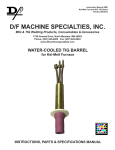
WATER-COOLED TIG MACHINE BARREL
Model TM500
Code No. 15506 (Barrel Only)
Water-Cooled Nozzle 11147
Uses Ceramic Gas Nozzles
INSTRUCTION, PARTS & SPECIFICATIONS MANUAL
D/F MACHINE SPECIALTIES is a world leader in the design, development, and manufacture of “MIG” (GMAW) & “TIG” (GTAW) welding products, consumables and accessories. D/F offers several types of manual Air or Water-Cooled “MIG” welding tools, and with the
increased use of automated and robotic welding systems, a demand has been created for welding tools of the highest quality, durability
and interchangeability. For over forty years, D/F welding products have been used extensively on “MIG” and “TIG” welding applications.
This experience, coupled with patented design features, unavailable on any other competitive equipment, has made D/F welding tools
the most advanced “MIG” and “TIG” welding guns and barrels for semi-automatic, automatic or robotic welding applications.
This Catalog is a guide to helping you select the proper tool for a given semi-automatic, automatic or robotic welding application. The following is only a partial listing of available semi-automatic, automatic and robotic guns. For further information on special “MIG” and “TIG”
requirements, please consult the factory.
Customer satisfaction and customer benefits are the center
points of all strategic contents
The spirit of the D/F Machine Specialties personnel is to listen to
and to integrate the customer throughout the process, to develop
and design marketable products, to present prototypes, to carry
out pilot tests and to prepare for and be open to new technology
and tasks. We attract and carefully select talented individuals
who share our values. Together we will nurture and sustain a
work environment with two-way communication, training, mentoring, and rewarding career opportunities.
Innovation and quality
Innovation and quality come from being receptive and willing to
learn from others. We encourage our people to be creative and
take risks in the pursuit of excellence. Innovative practices are
deeply rooted in every one of our employees, a philosophy that
leads to continuous product development and industry firsts.
Progress
By remaining confident, focused, and persistent in challenging
times, we will discover opportunity. Commitment to quality and
the pursuit on innovation ensure that D/F Machine Specialties
will remain an industry leader for years to come.
Commitment to excellence
At D/F Machine Specialties we commit to design, build and deliver premium products and superior customer support to quality
driven welding professionals. Customers still to this day choose
D/F over competitors because of our responsiveness and flexibility. Customers will continue to choose D/F tomorrow for our
superior hand-made products and service. To ensure this, we
need creative and competent personnel in all business divisions,
an intensive exchange of thoughts and ideas with all users, participation in working and study groups within the field of welding
technology and intensive cooperation with institutes and universities.
Teamwork
Striving for excellence is a commitment that is an integral component of the D/F Culture. Our team of skilled and dedicated
employees takes pride in the excellence products they produce.
Each of us willingly accepts personal responsibility for meeting
our commitments and we hold each other to a high standard of
accountability.
Responsibility
We will continually strive to be environmentally responsible and
to support the health and safety of our employees, customers,
and neighbors. We continue to support the communities in which
we operate and the industries in which we participate.
Thank You for Choosing D/F Machine Specialties
TABLE OF CONTENTS
Safety.............................................................................................................................4
Introduction, (Table 1) Recommended Spare Parts.......................................................5
Disassembly, Assembly..................................................................................................6
Disassembly Sequence..................................................................................................7
Required Tools List for Disassembly & Assembly........................................................8-9
Model TM500 W/C Top Load TIG Barrel - Parts...........................................................10
Model TM500 Ordering Information, Mounting............................................................. 11
Utility Station................................................................................................................12
Troubleshooting.......................................................................................................13-14
SAFETY MEASURES - **PLEASE READ!**
Welding is not particularly hazardous when certain safety practices are followed. Anyone using this equipment should be thoroughly
trained in safe welding practices. Failure to observe safe practices may cause serious injury. Handling welding torches presents no danger if the appropriate safety regulations are strictly adhered to. For example:
• Starting-up procedures must be reserved for those fully conversant with processes relating to arc welding equipment.
• Arc welding can prove damaging to eyes, skin, and hearing! It is therefore imperative that the Accident Prevention Regulations UVV 26.0 and VGB 15 are
fully observed and that all protective clothing, eye and ear protectors specified are worn.
• The load data given are maximum limit figures. Overloading will inevitably damage the torch!
• Before changing wear parts, disconnect for the power supply.
• The operating instructions for the individual welding components - e.g. power source, wire feed and cooling unit must be followed.
• Never pull the cable assembly across sharp edges or set down close to weld spatter or on a hot workpiece.
• Those not involved in the welding process should be protected by curtains or partitions from radiation and the danger of being dazzled.
• When handling gas cylinders, consult the instructions issued by the manufacturers and the suppliers of the pressurized gas.
• Workpieces which have been degreased using chlorinated solvents must be sprayed down with clean water before welding starts to avoid the risk of
phosgene forming. For the same reason, no degreasing baths containing chlorine must be placed close to the welding point.
• All vapors given off by metals can cause harm and a special warning is attached to lead, cadmium, copper, zinc, and beryllium. If necessary, take appropriate precautions (by providing adequate ventilation or an extraction system) to ensure that the legal maximum levels of toxic concentrations are not
exceeded.
For more information, refer to the following standards in their latest revisions and comply as applicable.
• ANSI Standard Z49.1, SAFETY IN WELDING AND CUTTING obtainable from the American Welding Society, 2501 N.W. 7th St., Miami, FL 33125.
• ANSI Standard Z41.1, STANDARD FOR MEN’S SAFETY - TOE FOOTWEAR obtainable from the American National Standards Institute, 1430 Broadway,
New York, NY 10018.
• ANSI Standard Z49.2, FIRE PREVENTION IN THE USE OF CUTTING AND WELDING PROCESSES obtainable from the American National Standards
Institute, 1430 Broadway, New York, NY 10018.
• OSHA, SAFETY AND HEALTH STANDARDS, 29CRF 1910, obtainable from the U.S. Government Printing Office, Washington, D.C. 20402.
• AWS Standard A6.0, WELDING AND CUTTING CONTAINERS WHICH HAVE HELD COMBUSTABLES obtainable from the American Welding Society,
2501 N.W. 7th St., Miami, FL 33125.
• NFPA Standard 70-1978, NATIONAL ELECTRICAL CODE obtainable from the National Fire Protection Association, 470 Atlantic Avenue, Boston, MA
02210.
• ANSI Standard Z88.2, “Practice for Respiratory Protection” obtainable from the American National Standards Institute, 1430 Broadway, New York, NY
10018.
• ANSI Standard Z87.1, SAFE PRACTICES FOR OCCUPATION AND EDUCATIONAL EYE AND FACE PROTECTION obtainable from the American
National Standards Institute, 1430 Broadway, New York, NY, 10018.
• NIOSH, SAFETY AND HEALTH IN ARC WELDING AND GAS WELDING AND CUTTING obtainable from the Superintendent of Documents, U.S. Printing
Office, Washington, D.C. 20402.
• American Welding Society Standard AWSF4.1 “Recommended Safe Practices for the Preparation for Welding and Cutting of Containers and Piping That
Have Held Hazardous Substances”, obtainable from the American Welding Society, 2501 N.W. 7th St., Miami, FL 33125.
IMPORTANT
The D/F torch is famous for the fact that if it is chilled properly, the welder can grab the front of the torch with their bare hand and it will be
cold to the touch seconds after welding. With the proper chiller, this can be done even after a 4 hour arc time.
Make certain the cooling water supply is at least the minimum flow rate of 3 quarts per minute (for each inner body), at 40 psi (80 psi
maximum) with a 5 gallon reservoir and 15,000 BTU/hr cooling capacity. Gun ratings are affected by shielding gas used, arc time, cooling
time and inlet water temperature. Water outlet temperature should not exceed 27°C (80°F). The torch’s water out & power cable is not
cooled until the coolant has gone through the torch and out the water out & power cable. If water is not flowing through the D/F torch for
at least 1 minute prior to striking an arc, when you apply the power and water hits the “hot” water/out & power cable, you will generate
steam. Steam can damage the torches internals in seconds causing a leak. It can also blow out the torches water/out & power cable. A
flow switch can be installed after the return line ensuring that coolant is present at the return line prior to striking an arc.
When High-Deposition GMAW or extended periods of arc time are used, it is recommended that a liquid chiller be considered with a
larger reservoir and a minimum of 30,000 BTU/hr cooling capacity. Precise temperature control maintains the cooling at a constant 13°C
(55°F) temperature, thus prolonging the life of the welding equipment and more specifically extending the service life of the gas nozzle
and current tip.
A refrigerated liquid chiller for GMAW may be obtained from:
For single torch chillers: Dynaflux - 800-334-4420 - www.dynaflux.com
For multiple torch cooling systems: Koolant Koolers - 800-968-5665 - www.koolantkoolers.com
INTRODUCTION
The D/F Model TM500 (Tungsten Machine 500 amp) water-cooled barrel is for use in semi-automatic or automatic machine
applications of the tungsten inert arc process.
A unique feature of this water-cooled TIG barrel is that the nozzle assembly water chamber and the inner body water chamber are serially connected to each other, thus completely eliminating the need for gaskets or O-rings in the water passage
system.
Maximum current rating with thoriated tungsten electrodes is 500 amperes DC straight polarity, and 300 amperes AC; high
frequency may be superimposed over standard current on a continuous or intermittent basis.
There are five (5) collets available for use with this machine barrel in sizes .040”, 1/16”. 3/32”, 1/8”, and 5/32”. The tubular
dual collet design provides clamping pressure at two points when the collet is securely fastened.
For further information or help with D/F Machine Specialties products, please visit our web site at
www.dfmachinespecialties.com, or consult the factory at 1-507-625-6200.
TABLE 1 - RECOMMENDED SPARE PARTS
ITEM
Gas Nozzle
Tungsten Sleeve
Collet Adapter
Spatter Disc
Insulation Tube
Insulator
O-ring
CODE NO.
To Be Selected
To Be Selected
15881
10405
16475
16473
16476
MIN QTY.
1
1
1
1
1
1
1
5
DISASSEMBLY
To disassemble the Water-Cooled Barrel, proceed as follows:
1) Remove the forward gas nozzle.
2) Remove the nut which fastened the Water-Cooled Nozzle to the body housing.
3) With a screw driver removed the barrel body holding screws. The upper shell may now be removed from the barrel
body.
4) Push the barrel body upward until the milled slots bottom out at service connections. The nylon insulators at the front water hose fittings are now exposed. Push these into the body housing concaves which will expose the interconnection water
hose fittings. With a 5/16” open end wrench unscrew the water hose nuts from the water-cooled nozzle body. Following this
the body housing may be removed from the inner body.
5) Part replacement may now be performed.
ASSEMBLY
1) To assemble the Water-Cooled Barrel, attach the short interconnection hose assembly to the upper block of the inner
body. Connect the long interconnection hose to the fitting at the rear of the front inner body block. It is recommended that at
this point a leak test be made by attaching the interconnection hose fittings to the water-cooled nozzle. Apply a water hose
to one of the service connections and make a visual inspection for leaks at the two connections made within the inner body
assembly.
2) Place the long interconnection hose into the concave of the inner body with it extending outward from the inner body.
Place the inner body assembly into the barrel body until it bottoms out at service connections.
3) Insert the two (2) nylon insulating tubes over the interconnection hose fittings.
4) The nylon collar should be in place on the rear of the water-cooled nozzle assembly. It is important that the small hole in
the nylon collar be on the lower right hand side as the water-cooled nozzle is connected to the hose fittings. After fastening the hoses, the barrel body should be moved forward until the flat head body screw may be fastened. The water-cooled
nozzle may now be pushed back against the barrel body.
5) Slide upper barrel body shell into place and fasten with screw. The body nut may now be applied.
6) Place the gas diffuser (D/F #15858), with parts facing forward on inner body. Replace insulation tube (D/F #15879) and
apply collet adapter (D/F #15914) with wrench supplied.
7) Replace the gas nozzle.
NOTE: When replacing the spatter disc (D/F #10405), use wrench supplied (D/F #12111) and unscrew the collet adapter.
The spatter disc must be placed on the collet adapter with the counter-bored end facing the front
6
DISASSEMBLY SEQUENCE
a. Unscrew the gas nozzle
a. With a screw driver remove the
slotted screw (A) and (B)
b. Remove the upper shield (C)
from barrel housing
a. Remove the collet adapter and
spatter disc with wrench supplied
a. Slide the barrel housing upward
until the milled slots bottom out at
service connections (A).
b. Nylon insulation tubes will now
be exposed. By pushing the tubes
upward into the barrel housing the
interconnection water hose nut
(B) and (C) attached to the watercooled nozzle will be exposed.
c. With a 5/16” open end wrench
remove (B) and (C).
d. The water-cooled nozzle body
may now be removed.
7
a. Unscrew the barrel housing nut.
a. Unscrew the barrel housing nut.
REQUIRED TOOLS LIST FOR DISASSEMBLY & ASSEMBLY
1. D/F 12111 Collet/Tip Wrench - This is the only tool that should ever be used to tighten the collet adapter. Pressure should be 30 lbs.,
or as snug as hand tightened. Never use another wrench to apply more torque to this wrench.
3. Long 5/16” Open Ended Wrench
A. A short wrench will work, however we prefer the feel and comfort of the long 5/16” open ended wrench. This is used to loosen or
tighten interconnection hoses (10974 & 13971) to the 7mm fitting on the inner body.
B. Also use this wrench to connect the torch’s water-cooled nozzle assembly to the interconnection hoses.
4. 3/8” Open Ended Wrench
A. This is used on the inner body’s water in hose fitting to secure the water in hose to the torch’s inner body. A crescent wrench could
be used instead, but due to the large size of crescent wrenches, we prefer the smaller size of the open ended wrenches. You never
want to use excessive force by using too large of a wrench. You will use the Long 7/16” Open Ended Wrench for the fitting on the
water in hose itself while using the 3/8” wrench to steady the inner body at the fitting. (see #5 A)
B. This is used on the inner body’s gas hose fitting to secure the gas hose to the torch’s inner body. A crescent wrench could be used
instead, but due to the large size of crescent wrenches, we prefer the smaller size of the open ended wrenches. You never want
to use excessive force by using too large of a wrench. You will use the Long 7/16” Open Ended Wrench for the fitting on the gas
hose itself while using the 3/8” wrench to steady the inner body at the fitting. (see #5 B)
5. Long 7/16” Open Ended Wrench
A. This is used to secure the water in hose to the torch’s inner body. (see #4 A)
B. This is used to secure the gas hose to the torch’s inner body. (see #4 B)
6. 9/16” & 1/2” Open Ended Wrench
A. This is used on the inner body’s water out & power cable fitting to secure the water out and power cable to the torch’s inner body.
A crescent wrench could be used instead, but due to the large size of crescent wrenches, we prefer the smaller size of the open
ended wrenches. We prefer the use of the larger wrenches on the power cable fitting to ensure that there are no water leaks, and
that it has been seated correctly. You will use the #7 (Long 9/16” Open Ended Wrench) for the fitting on the water out & power
cable hose. (see #7 A)
B. This wrench is also used to secure the adapter and jam nut that hold the current tip to the inner body. In your left hand hold the
inner body, and with your right hand thread up the adapter using the 1/2” Open Ended Wrench until it is tight. Now place the same
wrench on the jam nut and snug it up against the inner body. Keeping that wrench on the jam nut and placing it on the table for
force, take #7 (Long 1/2” Open Ended Wrench), place it on the adapter and push it down (counter-clockwise) securing the adapter
to the inner body. (see #7 B)
7. Long 1/2” & 9/16” Open Ended Wrench
A. This is used to secure the water out & power cable to the torch’s inner body. A medium size adjustable crescent wrench could be
used as well. We prefer the use of the larger wrenches on the power cable fitting to ensure that there are no water leaks, and that
it has been seated correctly. (see #6 A)
B. This wrench is also used to secure the adapter and jam nut to the inner body. (see #6 B)
C. This is used to secure the gas hose to the torch’s inner body. A crescent wrench could be used instead, but due to the large size
of crescent wrenches, we prefer the smaller size of the open ended wrenches.
8. Adjustable Crescent Wrench - A medium size adjustable crescent wrench could be used as well. We prefer the use of the larger
wrenches on the power cable fitting to ensure that there are no water leaks, and that it has been seated correctly. CAUTION: Never
use excessive force with large wrenches, for you could twist or break parts.
9. Standard Flat Head Screwdriver - This is used to tighten or secure the torch’s body screw. Also, the screwdriver can be used to
straighten the collet adapter if it is not aligned in the center of the gas cup or water-cooled nozzle CAUTION: This cannot be done
unless the spatter disc has been removed from the torch.
10.Long Nose Pliers - These are used to grab the small white insulation tubes (10723) and get them into the correct position when working on the interconnection hose fittings inside the torch. Also they are very handy when changing a slip-in contact tip.
11. 1/16” Allen Wrench - This is used to secure the socket set screw that holds the knob on the collet fastening shaft.
12.3/32” Allen Wrench - This is used to secure the socket cap screw that holds the shaft adapter in the top of the inner body.
8
REQUIRED TOOLS LIST FOR DISASSEMBLY & ASSEMBLY
9
WATER-COOLED TIG BARREL
MODEL TM500 (Code No. 15506)
32
5
6
1
28
18
19
20
2
21
7
22
26
11
4
12
13
25
14
15
16
13917
15511
15512
15871
15872
15873
15874
15875
O-ring (2 required)
Collet Fastening Shaft (with Knob)
Collet Fastening Shaft (less Knob)
Collet .040” Dia. Tungsten
Collet 1/16” Dia. Tungsten
Collet 3/32” Dia. Tungsten
Collet 1/8” Dia. Tungsten
Collet 5/32” Dia. Tungsten
Select Required Tungsten Size
Knob
Shaft Adapter
Interconnection Hose (Short)
Interconnection Hose (Long)
Inner Body Assembly
Adapter
Spatter Disc
Collet Adapter
Insulation Tubes (2 required)
Collar
Water-Cooled Nozzle
Insulator
Nut
Set Screw
Oval Head Screw (SS)
Outer Top Shell
Barrel Housing Assembly
Flat Head Screw (Nylon)
Sleeve (Cyclomatic Model 4608C)
Gas Nozzle 1/4”
Gas Nozzle 3/8”
Gas Nozzle 1/2”
Gas Nozzle 5/8”
Wrench
Tungsten Extension Rod
Tungsten Sleeve .040”
Tungsten Sleeve 1/16”
Tungsten Sleeve 3/32”
Tungsten Sleeve 1/8”
Tungsten Sleeve 5/32”
Boot
Nozzle Adapter
Adapter Insulation Tube
O-ring
Set Screw
25
26
27
17
30
1
2
4
5
6
7
8
9
10
11
12
13
14
15
16
17
18
19
20
21
22
23
24
24
3
Description
23
27
10
Code No.
3
8
9
Ref.
29
31
28
29
30
31
32
24
10
15850
15844
13971
13973
14027
12022
10405
15881
10723
10744
11147
15899
15930
14712
13975
13991
14035
12611
15920
15895
15896
15897
15898
12117
15860
15865
15866
15867
15868
15869
14050
16474
16475
16476
12540
TM500 MACHINE BARREL MOUNTING
CODE NO.
DESCRIPTION
15288
15289
15290
15291
15292
15293
TM500 3 Ft. Assembly
TM500 4 Ft. Assembly
TM500 5 Ft. Assembly
TM500 6 Ft. Assembly
TM500 8 Ft. Assembly
TM500 10 Ft. Assembly
TUNGSTEN CURRENT
MODEL
SIZE
CAPACITY
.040”-5/32”
500
TM500-3
.040”-5/32”
500
TM500-4
.040”-5/32”
500
TM500-5
.040”-5/32”
500
TM500-6
.040”-5/32”
500
TM500-8
.040”-5/32”
500
TM500-10
Cable/Hose Coupling
14430
2
3
Approx.
14.5”
1.625”
4
1
1”
1”
1.437”
.625” Dia.
REF.
1
2
3.5”
3
8”
Sleeve
1.625”
See Note*
4
3.125”
1.375”
*NOTE: Sleeve shown is used with Cyclomatic 4608C
Electromagnetic Probe
11
CODE NO.
14085
14451
14452
14453
13733
11904
11908
14501
14502
14503
14504
16830
11846
14461
14462
14463
14464
17046
12942
DESCRIPTION
Mounting Bracket
Water Out & Power Cable 3 Ft.
Water Out & Power Cable 4 Ft.
Water Out & Power Cable 5 Ft.
Water Out & Power Cable 6 Ft.
Water Out & Power Cable 8 Ft.
Water Out & Power Cable 10 Ft.
Gas Hose 3 Ft.
Gas Hose 4 Ft.
Gas Hose 5 Ft.
Gas Hose 6 Ft.
Gas Hose 8 Ft.
Gas Hose 10 Ft.
Water In Hose 3 Ft.
Water In Hose 4 Ft.
Water In Hose 5 Ft.
Water In Hose 6 Ft.
Water In Hose 8 Ft.
Water In Hose 10 Ft.
UTILITY STATION - STANDARD
DIMENSION SPECIFICATIONS
ORDERING INFORMATION
Description
Utility Station
Utility Station - Dual Power Cable
Code No.
45196
45188
Base Length
Overall Length
Base Width
Overall Width
Overall Height
Mounting Hole Center Distance
Overall Weight
3.75”
5.75”
2.25”
2.5”
3.125”
2.75”
3.5 lbs.
UTILITY STATION SIDE VIEW WITH COVER
D/F TORCH CONNECTION
Water In
Hose
5.75”
Water Out &
Power Cable
Gas
Hose
3.125”
3.75”
2.5”
FROM LEFT: D/F TORCH CONNECTION
FROM RIGHT: CUSTOMER UTILITIES CONNECTION
CUSTOMER UTILITIES CONNECTION
Water Out
(3/8” Hose Shank)
Water In
(3/8” Hose Shank)
Water Out &
Power Cable
Water Out
(3/8” Hose Shank)
Water In Hose
Voltage
Sensing
Lead
Shielding Gas
(3/16” Hose Shank)
Water In (3/8” Hose Shank)
Gas Hose
Shielding Gas
(3/16” Hose Shank)
4/0 Power
Cable
1.125”
2.75”
2 ea.
1/4”-20 Screws,
Lock Washers,
Nuts
12
TROUBLESHOOTING: POROSITY (SUMMARY)
NOTE: Most POROSITY is caused by gas problems, followed by base metal contamination.
Causes of Porosity
Possible Solutions
BASE METAL CONTAMINATION
Impurities on base metal
a. Remove contamination; clean surfaces
b. Use of specific wire/gas mix for specific types of impurities
FILLER METAL CONTAMINATION
Impurities on filler metal (wire)
a. Replace wire
b. Install wire-cleaning system
c. Prevent industrial dust/dirt/grit from contaminating wire during storage or use
d. Prevent build-up of aluminum oxide on exposed aluminum
wire surface by using up quickly
e. Remove wire from wire drive unit and store in a sealed plastic bag when not in use for long periods
ATMOSPHERIC CONTAMINATION
Drafts, wind, fans, etc.
a. Protect weld from drafts (curtains/screens)
b. Use tapered or bottleneck gas nozzles when drafts cannot
be avoided
GAS MIXING APPARATUS
1. Too high a gas flow, causing turbulence, and/or sucking air
at hose connections; creating the venturi effect at end of gas
nozzle
2. Too low a gas flow, causing insufficient gas coverage
3. Damaged or kinked gas lines
4. Too high an oxygen content
5. Leaks in gas distribution system
6. Other impurities in gas - moisture, etc.
7. Inconsistent gas flow (cfh) at the torch connection
1a. Reduce gas flow
1b. Tighten all hose connection points
2. Increase gas flow
3. Repair or replace
4. Adjust mixer
5. Repair leaks
6. Overhaul system; fit filters and/or dryers
7. Regulate pressure into flow meter for consistent cfh delivery
of gas
GAS TURBULENCE
1. Excessive spatter build-up in gas nozzle and on current tip
2. Nozzle damage, causing uneven gas coverage
3. Torch gas ports clogged or deformed
4. Super-heated nozzle, causing shielding gas to expand rapidly and create return effect at end of nozzle
5.Gas diffuser/nozzle insulator missing
6. Too high a gas flow causing the venturi effect
1. Clean nozzle and tip regularly; spray with anti-spatter fluid
2. Replace nozzle
3. Clean or replace
4. Check duty cycle rating of torch
5. Replace
6. Reduce gas flow
WELDING PARAMETERS, ETC.
1. Too long a wire stick-out; gas nozzle too far from weld
puddle
2. Bad torch position - too sharp a torch incline causing the
venturi effect at the end of the nozzle leading to atmospheric
contamination
3. Excessively wide weld pool for nozzle I.D.
1. Use longer nozzle or adjust stick-out (3/8” minimum or 15
times wire diameter)
2. Correct torch angle
3. Width of the weld pool should be 1.3 times the nozzle I.D.;
use suitable wider gas nozzle
4. Reduce voltage
5. Reduce speed
4. Arc voltage too high
5. Too high a travel speed
13
TROUBLESHOOTING: SPATTER
Possible Solutions
Problems/Causes
SPATTER
Too fast or too slow wire feed for the arc voltage
Set the wire feed rate and voltage in accordance with good welding practices as recommended by a qualified welding engineer.
Too long an arc
Adjust the wire feed and voltage so that the arc is in accordance
with good welding practice for the joint to be welded. The distance from the current tip to the workpiece should be 15 times
the welding wire diameter. If the arc is too long there will be spatter, usually in the direction of the weld.
Damaged current tip
If the current tip becomes worn the welding wire will not be in
constant contact with the tip and the arc will become unstable.
A current tip contaminated with spatter will cause uneven wire
feed resulting in further spatter.
Inclination of welding gun too great
The angle of the gas nozzle relative to the workpiece should be
between 45 and 90 degrees. If the angle is too small, the wire
runs parallel to the weld pool, resulting in spatter in the direction
of the welding.
Faulty power source
Have the power source checked for faulty conditions such as
broken wires and faulty contacts.
Incorrect start
A great deal of spatter occurs if the stick-out is too great and if
the welding gun is held too far from the workpiece when striking
the arc. Try to start with as short a stick-out as possible and with
the welding gun as close to the starting point as possible. If a
large ball end is formed on the end of the welding wire, remove
it by cutting the wire with sharp wire cutters. It is helpful if the
wire is cut to a point. Always remove the ball end before striking
an aluminum arc. Check the welding ground connection.
Incorrect pulse parameters
Check the user manual for your power supply or consult a qualified welding engineer.
Uneven wire feed
Uneven wire feed gives rise to heavy spatter. Find the cause of
the disturbance and correct the condition before proceeding.
Impurities on the base metal
Paint, mill scale, rust and other contamination on the base metal
form an insulating layer causing an unstable arc that results in
heavy spatter. Clean the surfaces to be welded.
Poor ground contact
Inspect ground cable for loose connections, fraying and cuts.
Correct any problem areas found and attach the ground cable
directly to the workpiece after having cleaned the contact surface first. POOR GROUND CONTACT IS THE MOST COMMON CAUSE OF UNSTABLE MIG WELDING CONDITIONS.
Too long stick-out (short-arc welding)
The stick-out should be 15 times the diameter of the wire electrode being used. With increasing stick-out, the current is reduced and the arc voltage rises, giving a longer unstable arc
and increased spatter.
Incorrect polarity
Check for correct polarity. Follow the electrode manufacturer’s
recommendations.
14
TROUBLESHOOTING: GENERAL GUIDE
Problems/Causes
ERRATIC WIRE FEED
Slipping feed rolls
Possible Solutions
Check that the feed roll size is correct for the wire size being used. Increase the
drive roll pressure until the wire feed is even. Do not apply excessive pressure as
this can damage the wire surface, causing copper coating to loosen from steel
wires or metal shavings to be formed from soft wires like aluminum. These metal
fragments or shavings can be drawn into the wire feed conduit and will rapidly
clog the liner. When welding with flux-cored wires, excessive drive roll pressure
may open the wire seam and allow flux or metal powders to escape.
Clogged or worn gun liner
a. Dust, particles of copper, drawing lubricants, metal or flux and other forms of
contamination can all clog the liner so that the wire feed is slowed or impeded. A
liner that has been in use for an extended period of time becomes worn and filled
with dirt and must be replaced.
b. When changing the welding wire, remove the tip from the front end of the
gun and blow out the body liner with clean, dry compressed air from the back of
the gun. Repeat with the casing and liner assembly. Note: Wear safety goggles
when using compressed air to clean the liners. Make sure proper safety procedures are followed in order to avoid possible serious eye injury.
Liners too long or too short
Check the lengths of the liners and trim or replace if too long or too short. The
efficient feeding of the welding wire is dependent on the liners fitting correctly.
Spatter on the wire
Coil brake incorrectly adjusted
UNSTABLE ARC
Incorrect setting of voltage and/or current
Problems in wire feeding: worn current tip
Impurities on the base metal
Poor contact between ground cable and workpiece or loose power connection
Stick-out too long
An unprotected coil of wire quickly collects dust and other airborne contamination. If grinding is being performed in the vicinity, particles can become attached
to the wire, severely interfering with the wire feed. Replace with clean wire and
keep it protected with a cover. Make sure spare wire rolls are stored in a clean,
dry place.
Set the brake so that the coil immediately stops rotating as soon as welding is
interrupted. If the brake is applied too hard it will cause the feed rolls to slip,
resulting in uneven wire feed. If it is too loose, overrun of the wire will occur,
causing wire tangles, inconsistent tension on the feed mechanism and irregular
arc characteristics.
Set the wire feed in relation to the arc voltage in such a way that the arc is stable
and burns evenly. In spray arc welding, set the wire feed so that there are no
short circuits and the filler metal is transferred in a spray across the arc. Find the
cause of the interference and correct it. (See ERRATIC WIRE FEED above)
When the internal diameter of the current tip becomes worn from the passage
of wire through it, the wire may no longer stay in continuous electrical contact
with the tip. This results in an unstable arc and an increase in spatter. Paint, mill
scale, silicon scale, rust or flux deposits from previous weld runs may form an
insulating layer causing an unstable arc. Clean the surfaces to be welded.
Securely attach the ground cable as close to the point of welding as possible on
the workpiece. Clean the surfaces thoroughly to ensure good contact.
Check to insure the welding power connection on the power source is tight, the
and workpiece. Connection on the wire feeder is tight, the connection to the
adaptor block is tight, Loose power connection and the connection of the gun to
the adaptor block is tight.
Adjust the current tip to work distance to a minimum of 3/8” for short arc welding.
A more precise distance is 15 times the wire diameter.
15
TROUBLESHOOTING: GENERAL GUIDE
Problems/Causes
AIR-COOLED GUN RUNNING TOO HOT
Poor ground
Possible Solutions
Inspect ground cable for loose connections, fraying and cuts. Correct any problem areas found. Clean clamping area to insure good contact. Securely attach
the ground cable to the workpiece, as close as possible to the point of welding.
Make sure there is a good connection to the welding power source.
Loose power connection
Check to make sure the power connection on the power source is tight, the connection on the wire feeder is tight, the connection to the adaptor block is tight,
and the connection of the gun to the adaptor block is tight.
Consumable items loose or worn
Remove nozzle from gun and inspect current tip, collet nut (tip holder) and spatter disc (gas diffuser) for wear and tightness; replace or tighten as necessary.
Capacity of gun being exceeded
Note complete weld parameters, including welding current (Amps), welding voltage, wire feed speed, type and size of wire, type of gas and flow rate of gas and
consult your local Authorized D/F Machine Specialties Distributor or contact the
factory.
Dirty connection
Remove torch and inspect parts for dirt build-up. Periodic cleaning is necessary.
16
D/F MACHINE SPECIALTIES, INC.
MIG & TIG Welding Products, Consumables & Accessories
WARRANTY
This Equipment is sold by D/F MACHINE SPECIALTIES, Incorporated, under the warranty set forth in
the following paragraph. Such warranty is extended only to the buyer who purchases the equipment
directly from D/F or its authorized distributor as new merchandise.
The barrel and cable assemblies are warranted by D/F to be free from manufacturing defects for 90
days after delivery by D/F, provided that the equipment is properly operated under conditions of normal
use and that regular periodic maintenance and service is performed. Expendable parts are not warranted for any specific time. Expendable parts referred to herein would be the nozzles, current tips,
spatter discs, insulators, casing liners, and wire inlets. D/F’s sole obligation under this warranty is limited to making replacement at its manufacturing facility for barrel assemblies which are returned to it
with transportation charges prepaid, and upon D/F’s examination have been found to be so defective.
Genuine D/F MACHINE SPECIALTIES, Inc. Parts, Accessories, and Consumables must be used for
safety and performance reasons. The use of anything other than genuine D/F MACHINE SPECIALTIES, Inc. Parts, Accessories, or Consumables will void this Warranty. All units returned for warranty
repair are subject to Warranty Inspection. Warranty and repair work shall not apply to goods that have
been altered or repaired, have been subject to misuse or used while any parts are loose, broken, or
damaged, or used with other than original D/F® parts, consumables, or accessories which may affect
performance and safety.
D/F MACHINE SPECIALTIES, INC.
Rev. 140612-2
1750 Howard Drive
North Mankato, MN 56003
Phone: (507) 625-6200
Fax: (507) 625-6203
www.dfmachinespecialties.com