1
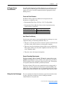
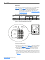
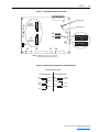
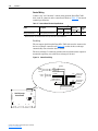
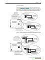
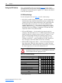
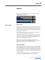
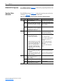
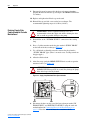
Liquid-to-Liquid Heat
Exchanger
User Manual
Important User Information
Solid state equipment has operational characteristics differing from those of
electromechanical equipment. Safety Guidelines for the Application,
Installation and Maintenance of Solid State Controls (Publication SGI-1.1
available from your local Rockwell Automation sales office or online at http://
www.rockwellautomation.com/literature) describes some important differences
between solid state equipment and hard-wired electromechanical devices.
Because of this difference, and also because of the wide variety of uses for solid
state equipment, all persons responsible for applying this equipment must
satisfy themselves that each intended application of this equipment is
acceptable.
In no event will Rockwell Automation, Inc. be responsible or liable for indirect
or consequential damages resulting from the use or application of this
equipment.
The examples and diagrams in this manual are included solely for illustrative
purposes. Because of the many variables and requirements associated with any
particular installation, Rockwell Automation, Inc. cannot assume responsibility
or liability for actual use based on the examples and diagrams.
No patent liability is assumed by Rockwell Automation, Inc. with respect to use
of information, circuits, equipment, or software described in this manual.
Reproduction of the contents of this manual, in whole or in part, without
written permission of Rockwell Automation, Inc. is prohibited.
Throughout this manual, when necessary we use notes to make you aware of
safety considerations.
!
WARNING: Identifies information about practices or
circumstances that can cause an explosion in a hazardous
environment, which may lead to personal injury or death, property
damage, or economic loss.
Important: Identifies information that is critical for successful application and
understanding of the product.
!
ATTENTION: Identifies information about practices or
circumstances that can lead to personal injury or death, property
damage, or economic loss. Attentions help you identify a hazard,
avoid the hazard, and recognize the consequences.
Shock Hazard labels may be located on or inside the equipment
(e.g., drive or motor) to alert people that dangerous voltage may be
present.
Burn Hazard labels may be located on or inside the equipment
(e.g., drive or motor) to alert people that surfaces may be at
dangerous temperatures.
Allen-Bradley and PowerFlex are registered trademarks of Rockwell Automation, Inc.
PowerFlex 700L Liquid-to-Liquid Heat Exchanger User Manual
Summary of Changes
This is the first release of the PowerFlex 700L Liquid-to-Liquid Heat
Exchanger User Manual.
PowerFlex 700L Liquid-to-Liquid Heat Exchanger User Manual
Publication 20L-UM002A-EN-P
soc-ii
Summary of Changes
PowerFlex 700L Liquid-to-Liquid Heat Exchanger User Manual
Publication 20L-UM002A-EN-P
Table of Contents
Preface
Overview
Who Should Use this Manual? . . . . . . . . . . . . . . . . . . . . . . . . . . . . . . . . . . . . . . . . . . . . .
Technical Support and Service . . . . . . . . . . . . . . . . . . . . . . . . . . . . . . . . . . . . . . . . . . . . .
What Is Not in this Manual . . . . . . . . . . . . . . . . . . . . . . . . . . . . . . . . . . . . . . . . . . . . . . . .
Reference Materials . . . . . . . . . . . . . . . . . . . . . . . . . . . . . . . . . . . . . . . . . . . . . . . . . . . . .
Introduction . . . . . . . . . . . . . . . . . . . . . . . . . . . . . . . . . . . . . . . . . . . . . . . . . . . . . . . . . . . .
Operating Principle . . . . . . . . . . . . . . . . . . . . . . . . . . . . . . . . . . . . . . . . . . . . . . . . . . . .
Component Details . . . . . . . . . . . . . . . . . . . . . . . . . . . . . . . . . . . . . . . . . . . . . . . . . . . .
General Precautions . . . . . . . . . . . . . . . . . . . . . . . . . . . . . . . . . . . . . . . . . . . . . . . . . . . . .
Catalog Number Explanation . . . . . . . . . . . . . . . . . . . . . . . . . . . . . . . . . . . . . . . . . . . . . .
Chapter 1
P-1
P-1
P-1
P-2
P-2
P-2
P-3
P-3
P-4
Installation
Installation Specifications . . . . . . . . . . . . . . . . . . . . . . . . . . . . . . . . . . . . . . . . . . . . . . . . . 1-1
Required Ambient Conditions. . . . . . . . . . . . . . . . . . . . . . . . . . . . . . . . . . . . . . . . . . . . 1-1
Location Requirements . . . . . . . . . . . . . . . . . . . . . . . . . . . . . . . . . . . . . . . . . . . . . . . . . 1-1
Lifting Instructions . . . . . . . . . . . . . . . . . . . . . . . . . . . . . . . . . . . . . . . . . . . . . . . . . . . . 1-2
Drive Coolant Requirements . . . . . . . . . . . . . . . . . . . . . . . . . . . . . . . . . . . . . . . . . . . . . 1-3
Connecting the Elbow/Strainer Assembly (shipped loose). . . . . . . . . . . . . . . . . . . . . . 1-4
Supply Loop Liquid Quality, Maintenance, and Precautions . . . . . . . . . . . . . . . . . . . . 1-5
Pre-Connection Pipe Flushing. . . . . . . . . . . . . . . . . . . . . . . . . . . . . . . . . . . . . . . . . . . . 1-5
Connecting Hoses to the Heat Exchanger . . . . . . . . . . . . . . . . . . . . . . . . . . . . . . . . . . . . . 1-6
Drive Loop (from Heat Exchanger to Drive) . . . . . . . . . . . . . . . . . . . . . . . . . . . . . . . . 1-6
Supply Loop (from Heat Exchanger to Cooling Liquid Source) . . . . . . . . . . . . . . . . . 1-7
Removing Top and Side Panels. . . . . . . . . . . . . . . . . . . . . . . . . . . . . . . . . . . . . . . . . . . . . 1-8
AC Supply Source Considerations . . . . . . . . . . . . . . . . . . . . . . . . . . . . . . . . . . . . . . . . . . 1-9
Fuses and Circuit Breakers . . . . . . . . . . . . . . . . . . . . . . . . . . . . . . . . . . . . . . . . . . . . . . 1-9
Input Power Conditioning . . . . . . . . . . . . . . . . . . . . . . . . . . . . . . . . . . . . . . . . . . . . . . . 1-9
General Grounding Requirements. . . . . . . . . . . . . . . . . . . . . . . . . . . . . . . . . . . . . . . . . 1-9
Wiring the Heat Exchanger . . . . . . . . . . . . . . . . . . . . . . . . . . . . . . . . . . . . . . . . . . . . . . . . 1-9
Power Wiring. . . . . . . . . . . . . . . . . . . . . . . . . . . . . . . . . . . . . . . . . . . . . . . . . . . . . . . . 1-10
Control Wiring . . . . . . . . . . . . . . . . . . . . . . . . . . . . . . . . . . . . . . . . . . . . . . . . . . . . . . 1-12
Setting the DIP Switches. . . . . . . . . . . . . . . . . . . . . . . . . . . . . . . . . . . . . . . . . . . . . . . . . 1-14
S1 DIP Switch Settings . . . . . . . . . . . . . . . . . . . . . . . . . . . . . . . . . . . . . . . . . . . . . . . . 1-14
S2 DIP Switch Settings . . . . . . . . . . . . . . . . . . . . . . . . . . . . . . . . . . . . . . . . . . . . . . . . 1-15
CE Conformity . . . . . . . . . . . . . . . . . . . . . . . . . . . . . . . . . . . . . . . . . . . . . . . . . . . . . . . . 1-16
Low Voltage Directive (73/23/EEC) . . . . . . . . . . . . . . . . . . . . . . . . . . . . . . . . . . . . . . 1-16
EMC Directive (89/336/EEC) . . . . . . . . . . . . . . . . . . . . . . . . . . . . . . . . . . . . . . . . . . . 1-16
Pressure Equipment Directive (97/23/EC) . . . . . . . . . . . . . . . . . . . . . . . . . . . . . . . . . 1-16
Essential Requirements for CE Compliance . . . . . . . . . . . . . . . . . . . . . . . . . . . . . . . . 1-16
C-Tick Conformity . . . . . . . . . . . . . . . . . . . . . . . . . . . . . . . . . . . . . . . . . . . . . . . . . . . . . 1-16
PowerFlex 700L Liquid-to-Liquid Heat Exchanger User Manual
Publication 20L-UM002A-EN-P
ii
Table of Contents
Chapter 2
Operation
Drive Interaction . . . . . . . . . . . . . . . . . . . . . . . . . . . . . . . . . . . . . . . . . . . . . . . . . . . . . . . .
Normal Operation . . . . . . . . . . . . . . . . . . . . . . . . . . . . . . . . . . . . . . . . . . . . . . . . . . . . .
Loss of Flow Operation . . . . . . . . . . . . . . . . . . . . . . . . . . . . . . . . . . . . . . . . . . . . . . . . .
PRIME SWITCH Operation . . . . . . . . . . . . . . . . . . . . . . . . . . . . . . . . . . . . . . . . . . . . . . .
Operating Status Indications . . . . . . . . . . . . . . . . . . . . . . . . . . . . . . . . . . . . . . . . . . . . . . .
Adding Coolant to the Drive Loop for Start-Up . . . . . . . . . . . . . . . . . . . . . . . . . . . . . . . .
Draining Supply Side Cooling Loop for Periodic Maintenance . . . . . . . . . . . . . . . . . . . .
Draining Coolant from the Drive Loop for Periodic Replacement . . . . . . . . . . . . . . . . . .
Appendix A
2-1
2-1
2-1
2-2
2-2
2-3
2-4
2-5
Supplemental Heat Exchanger Information
Specifications. . . . . . . . . . . . . . . . . . . . . . . . . . . . . . . . . . . . . . . . . . . . . . . . . . . . . . . . . . . A-1
Control Board Replacement Fusing. . . . . . . . . . . . . . . . . . . . . . . . . . . . . . . . . . . . . . . . . . A-1
Appendix B
Heat Exchanger Schematic
PowerFlex 700L Liquid-to-Liquid Heat Exchanger User Manual
Publication 20L-UM002A-EN-P
Preface
Overview
The purpose of this manual is to provide you with the installation and
operating information for the PowerFlex 700L Liquid-to-Liquid Heat
Exchanger used with PowerFlex 700L Liquid-Cooled drives and power
modules.
For information on…
Who Should Use this Manual?
Technical Support and Service
What Is Not in this Manual
Reference Materials
Introduction
General Precautions
Catalog Number Explanation
See page…
P-1
P-1
P-1
P-2
P-2
P-3
P-4
Who Should Use this
Manual?
This manual is intended for qualified personnel. You must be able to install,
wire, and operate Adjustable Frequency AC Drive devices.
Technical Support and
Service
For Allen-Bradley Drives Technical Support online:
www.ab.com/support/abdrives
For service or replacement parts, contact:
Dimplex Thermal Solutions in Kalamazoo, Michigan
1-800-968-5665
What Is Not in this Manual
This manual is designed to provide only heat exchanger information. For
detailed PowerFlex 700L drive information:
Title
PowerFlex 700L Liquid-Cooled Adjustable Frequency AC Drive User Manual
PowerFlex 700L Active Converter Power Module User Manual
Publication
20L-UM001…
PFLEX-UM002…
Publications can be obtained online at
http://www.rockwellautomation.com/literature.
PowerFlex 700L Liquid-to-Liquid Heat Exchanger User Manual
Publication 20L-UM002A-EN-P
P-2
Overview
Reference Materials
The following manuals are recommended for general drive information:
Title
Wiring and Grounding Guidelines for Pulse Width Modulated (PWM) AC Drives
Preventive Maintenance of Industrial Control and Drive System Equipment
PowerFlex 70/700 Reference Manual
Safety Guidelines for the Application, Installation, and Maintenance of Solid State
Control
A Global Reference Guide for Reading Schematic Diagrams
Guarding Against Electrostatic Damage
Introduction
Publication
DRIVES-IN001…
DRIVES-TD001…
PFLEX-RM001…
SGI-1.1
0100-2.10
8000-4.5.2
Operating Principle
The operating principle of the heat exchanger is based on liquid-to-liquid
transfer of heat (Figure P.1). The drive loop transports the heat load from the
drive to the heat exchanger. The supply loop flows through the heat
exchanger to collect the heat load and transports it to the user’s cooling
system liquid source. The use and choice of a system for disposing of the
heat load is the user’s responsibility.
Figure P.1 Liquid Flow Heat Transfer Diagram
Drive Loop
Supply Loop
The liquid-to-liquid heat exchanger uses a heat transfer plate to transfer heat
from one liquid to another. This method requires a stable water supply from
the user.
Figure P.2 Drive and Heat Exchanger Plumbing Arrangement
Liquid-to-Liquid
Heat Exchanger
PowerFlex 700L
Drive
Inlet
Drive
Outlet
Hose Kit
From
Drive
Outlet
To
Drive
Inlet
Return
In
To
From
Supply Supply
Customer
Supplied Piping
To Facility Water
= hose or pipe connection
PowerFlex 700L Liquid-to-Liquid Heat Exchanger User Manual
Publication 20L-UM002A-EN-P
Overview
P-3
Component Details
Figure P.3 shows a cooling loop diagram for a typical liquid-to-liquid heat
exchanger.
Figure P.3 Liquid-to-Liquid Heat Exchanger Plumbing Diagram
Ambient Sensor
TE
Control
Valve
Flow Switch
TE
FS
Strainer
IN
OUT
OUT
Heat Exchanger
Supply
Process
Water
Drive Coolant Temp.
IN
Level Switch
LS
IN
Reservoir
OUT
Drive
Pump
The main components of the cooling loop include:
Part
Strainer
Control Valve
Heat Exchanger Plate
Ambient Sensor
Drive Coolant Temperature
Sensor
Drive Coolant Flow Switch
Level Switch
Reservoir
Pump and Motor
General Precautions
!
!
Description
Filters particles from the supply water.
Controls the supply loop water flow.
Transfers heat from the drive loop to the supply loop.
Senses the ambient temperature used for the dew point control.
Senses the drive coolant temperature used for the dew point control.
Measures the drive coolant flow rate.
Senses the level of coolant in the reservoir.
Stores drive coolant.
Circulates drive coolant.
ATTENTION: An incorrectly applied or installed heat exchanger
can result in component damage or a reduction in product life.
Wiring or application errors, such as, undersizing the heat
exchanger, incorrect or inadequate AC supply, or excessive
ambient temperatures may result in malfunction of the system.
ATTENTION: Only qualified personnel familiar with adjustable
frequency AC drives and associated machinery should plan or
implement the installation, start-up, and subsequent maintenance
of the system. Failure to comply may result in personal injury and/
or equipment damage.
PowerFlex 700L Liquid-to-Liquid Heat Exchanger User Manual
Publication 20L-UM002A-EN-P
P-4
Overview
Catalog Number
Explanation
1-3
4
5-6
20L – LL
a
b
12
c
A
d
e
a
d
Hose Connection
Type
PowerFlex 700L
Code
P75
1P0
Size
0.75 inch NPT
1.0 inch NPT
b
e
Heat Exchanger
Option
Code
LL
Type
Liquid-to-Liquid
c
Rating
PowerFlex 700L Liquid-to-Liquid Heat Exchanger User Manual
Publication 20L-UM002A-EN-P
11
13K – P75
Drive
Code
20L
Code
13K
24K
Position
7-9 10
Watts
13,000
24,000
Code
A
Description
Reserved
Chapter
1
Installation
This chapter provides information on installing and wiring the PowerFlex
700L Liquid-to-Liquid Heat Exchanger.
For information on…
Installation Specifications
Connecting Hoses to the Heat Exchanger
Removing Top and Side Panels
AC Supply Source Considerations
Wiring the Heat Exchanger
Setting the DIP Switches
CE Conformity
C-Tick Conformity
Installation Specifications
See page…
1-1
1-6
1-8
1-9
1-9
1-14
1-16
1-16
Required Ambient Conditions
The heat exchanger is designed to work within these ambient temperatures:
Heat Exchanger
20L-LL13K-P75A
20L-LL13K-P75A
20L-LL24K-1P0A
When Used With
Drive Size
Frame 2
Frame 3A
Frame 3B
Ambient
Temperature Range
0-50°C (32-122°F)
0-40°C (32-104°F)
0-40°C (32-104°F)
It is the user’s responsibility to ensure that the temperature remains within
this limit during operation. Condensation cannot be allowed to form in the
drive. The easiest way of preventing condensation inside the drive is by
keeping the water temperature in the supply loop higher than the ambient
temperature. Circulate coolant through the drive only when the drive is
powered – except as described in Adding Coolant to the Drive Loop for
Start-Up on page 2-3.
!
ATTENTION: Risk of equipment damage exists. Failure to
keep the coolant temperature in the drive loop higher than the
ambient temperature may result in condensation accumulating on
the drive heatsink and/or circuit boards, which could damage the
drive.
Location Requirements
Place the heat exchanger in a suitable location not more than 9.1 m (30 feet)
from the drive. The location must be on the same level (altitude) as the drive
to prevent increasing the load on the heat exchanger coolant pump. Refer to
Figure 1.1 for overall dimensions of the heat exchanger and locations of
hose connections for the drive loop and supply loop.
PowerFlex 700L Liquid-to-Liquid Heat Exchanger User Manual
Publication 20L-UM002A-EN-P
1-2
Installation
Lifting Instructions
The heat exchanger can be lifted off the shipping skid by removing the
packing material from the unit and unscrewing the mounting brackets lag
screws from the skid.
Using a Lift Truck
Forks a can be inserted between the exchanger legs from the front or sides
as long as the forks extend beyond the opposite surface. Note: Bottom
sections of the exchanger are open.
Using Rigging Straps
Rigging straps should be placed under the unit and along the sides to lift
from the top. These straps should be long enough to provide fill tube
clearance on the top.
Figure 1.1 Heat Exchanger Dimensions and Coolant Connections
Dimensions are in
millimeters and (inches).
619 Max.
(24.4)
688 Max.
(27.1)
FILL TUBE
127 Max.
(5.0)
Data
Nameplate
TOP
POWER
Fluid Level
FROM DRIVE OUTLET
CONTROL
WIRING
781 Max.
(30.77)
616 Max.
(24.3)
38
+0.25/
-0.00
(1.5)
Electrical
Box
STATUS
Indicator
POWER
Indicator
258
(10.18)
TO DRIVE
INLET
740 Max.
289
(29.1)
(11.38)
RETURN TO
SUPPLY
172
(6.8)
102 Min.
(4.0)
304
(12.0)
INLET FROM SUPPLY
(Strainer shipped loose)
REAR
31 Max.
(1.25)
DRIVE
DRAIN
SUPPLY
DRAIN
PRIME SWITCH
FRONT
Heat Exchanger
20L-LL13K-P75A
20L-LL24K-1P0A
PowerFlex 700L Liquid-to-Liquid Heat Exchanger User Manual
Publication 20L-UM002A-EN-P
Approximate Weight
Empty (no coolant)
113 kg (250 lbs.)
113 kg (250 lbs.)
Installation
1-3
Drive Coolant Requirements
Table 1.A lists approved sources and recommended coolants with
appropriate corrosion inhibitors for the drive loop:
Table 1.A Recommended Drive Loop Coolants
Source
Interstate Chemical
Coolant
• NFP-50 (1); a 50/50 premix of propylene glycol and
distilled water
http://www.interstatechemical.com/
•
NFE-50 (1); a 50/50 premix of ethylene glycol and
contact.htm
distilled water
Koolant Koolers/Dimplex Thermal • K-Kool-E (1); ethylene glycol (available premixed with
Solutions
distilled water)
•
Propylene glycol (1) also available
http://www.koolantkoolers.com/
index.php/nic=contact
Dow Chemical
• Dowtherm® SR-1 (2); ethylene glycol
• Dowfrost® (2); propylene glycol
http://www.dow.com
Dowtherm and Dowfrost are registered trademarks of the
Dow Chemical Company
(1)
(2)
Available in 5 gallon pails.
Not premixed with distilled water, and may not be available in 5 gallon quantities.
Non-diluted coolants require a coolant-to-water mix ratio of 50% by
volume. Table 1.B lists the estimated amount of coolant needed for the drive
loop based on the drive frame size.
Table 1.B Estimated Coolant Amount for the Drive Loop
Drive Size
Frame 2
Frame 3A
Frame 3B
(1)
Estimated Amount of Coolant (1)
15.1 liters (4 gal.)
19 liters (5 gal.)
19 liters (5 gal.)
The estimated amount of coolant is based on the heat exchanger using 1.2 m
(4 ft.) hoses. Longer hoses require more coolant. The maximum hose length
of 9.1 m (30 ft.) would require up to an additional 2.8 liters (3/4 gal.).
Important: Since coolant performance slowly degrades over time, the drive
loop coolant should be replaced every two years and/or
whenever the loop is drained for servicing. See Draining
Coolant from the Drive Loop for Periodic Replacement on
page 2-5 for instructions.
If an approved coolant is not used, the drive coolant must consist of clean
water with a corrosion inhibitor. An approved corrosion inhibitor is
Chemtool, Inc. (www.chemtool.com) part number Watertool 4435-C. The
recommended concentration of the inhibitor is 8-10% by volume. Deionized
water is prohibited. Use distilled water or water with less than 50 ppm
concentrations of:
• Sulfate and chloride
• Hard water ions such as Mg++ and Ca++
PowerFlex 700L Liquid-to-Liquid Heat Exchanger User Manual
Publication 20L-UM002A-EN-P
1-4
Installation
!
ATTENTION: Ethylene and propylene glycols must be
inhibited and silicate free. Use of common silicate-containing,
automotive-type ethylene glycol solutions is prohibited as they
may damage the heat exchanger and/or drive and cooling
module equipment.
The drive coolant must be compatible with the following materials:
•
•
•
•
Copper
Brass
Aluminum
Arimid fiber gasket with nitrile binder (Garlock, Inc. Blue-Gard 3000®)
Blue-Gard 3000 is a registered trademark of Garlock, Inc.
Connecting the Elbow/Strainer Assembly (shipped loose)
1. Apply PTFE (Teflon®) thread sealing tape or pipe thread sealant
compound to threads on the "IN FROM SUPPLY" pipe nipple. Avoid
excessive tape or compound which may come loose in the cooling loop.
Apply only to threads that will contact mating parts.
Teflon is a registered trademark of DuPont.
2. Hold the pipe nipple with a pipe wrench and tighten the elbow/strainer
assembly onto the "IN FROM SUPPLY" pipe nipple with a second pipe
wrench (Figure 1.2). The strainer should be installed with the flow
direction as indicated on its body, in a vertical down or horizontal
pipeline. INSTALLATION IS NOT POSSIBLE WITH UPWARD
FLOW. The strainer must be accessible for periodic removal of
accumulated debris from its screen.
Figure 1.2 Connecting Strainer/Elbow
PowerFlex 700L Liquid-to-Liquid Heat Exchanger User Manual
Publication 20L-UM002A-EN-P
Installation
1-5
Supply Loop Liquid Quality, Maintenance, and Precautions
!
ATTENTION: The single walled heat exchanger is not
suitable for use in a potable water system. Do not connect the
supply return to a potable water system.
The supply loop liquid quality is not expected to be as clean as the drive loop
liquid. Clean water will prolong the time needed between cleanings and/or
replacement of the plate heat exchanger. A strainer with screen element is
provided on the input of the supply loop. This screen element is a 20 Mesh,
meaning it has 0.5 mm (0.020 in.) openings. When using a natural or
municipal source of water for the supply loop, sediments could clog the
strainer and openings between the exchanger plates causing the heat transfer
between the drive and supply loop to degrade over time. Scheduled yearly
maintenance to check, clean or replace the strainer element is recommended.
Additional supply liquid filtering may be required if water quality is poor
and supply loop fouling causes drive faults due to overheating. For
instructions to drain the supply loop for maintenance, see Draining Supply
Side Cooling Loop for Periodic Maintenance on page 2-4.
Pre-Connection Pipe Flushing
All piping to the drive or supply loop made by the user must be flushed to
remove debris before being connected to the heat exchanger.
PowerFlex 700L Liquid-to-Liquid Heat Exchanger User Manual
Publication 20L-UM002A-EN-P
1-6
Installation
Connecting Hoses to the
Heat Exchanger
Drive Loop (from Heat Exchanger to Drive)
Depending on the location of the heat exchanger relative to the drive, the
following drive cooling loop hose kits are available:
Table 1.C Drive Cooling Loop Hose Kits
Used With
Frame 2 and
13 kW heat exchanger
Frame 2 and
13 kW heat exchanger
Frame 3A and
13 kW heat exchanger
Frame 3A and
13 kW heat exchanger
Frame 3B and
24 kW heat exchanger
Frame 3B and
24 kW heat exchanger
(1)
Hose Kit
Hose
Catalog Number Length
20L-GH10-B1
3m
(10 ft.)
20L-GH30-B1
9.1 m
(30 ft.)
20L-GH10-A2
3m
(10 ft.)
20L-GH30-A2
9.1 m
(30 ft.)
20L-GH10-A1
3m
(10 ft.)
20L-GH30-A1
9.1 m
(30 ft.)
Hoses Drive Side(1) Heat Exchanger Side
in Kit Coupling Size Coupling Size
2
0.75 inch
0.75 inch
2
0.75 inch
0.75 inch
2
1 inch
1 inch with 90° elbow
2
1 inch
1 inch with 90° elbow
2
1 inch
1 inch
2
1 inch
1 inch
All drive side hose kit fittings are 37 degree flare.
Alternately, the following parts can be obtained from an appropriate supplier
to fabricate specific length hoses which must not exceed 9.1 m (30 ft.).
• 1-inch inside diameter hose Parker Hannifin p/n 801-16
• 1-inch swivel hose fitting female JIC (Joint Industrial Council) 37°
Parker Hannifin p/n 30682-16-16B
• 3/4-inch inside diameter hose Parker Hannifin p/n 801-12
• 3/4-inch swivel hose fitting female JIC (Joint Industrial Council) 37°
Parker Hannifin p/n 30682-12-12B
• 1-inch elbow Parker Hannifin p/n 16 CTX-B
!
ATTENTION: Risk of equipment damage exists. Hose fittings
must be brass or stainless steel. Use of plated steel fittings is
prohibited.
To attach a coupling to a hose, lubricate the inside of the hose end with a
small amount of liquid soap. Set the coupling down on a solid surface and
push the hose onto the coupling — in one firm push — until the hose end is
flush against the plastic bushing on the coupling. Stopping before the hose
is fully on may make it difficult to push the hose completely onto the
coupling.
Connect the two drive cooling loop hoses from the heat exchanger to the
drive. Mating hose connections for the drive loop are shown in Figure 1.3
and Figure 1.4. The mating process includes the following steps:
1. Assemble the mating version of the fitting (with swivel nut) to each drive
fluid fitting, and tighten to wrench resistance or 3.3 N-m (30 lb.-in.).
PowerFlex 700L Liquid-to-Liquid Heat Exchanger User Manual
Publication 20L-UM002A-EN-P
Installation
1-7
2. Using a backup wrench on the drive loop or drive fitting, tighten the
swivel nut fitting by either of the following two methods:
– Hex flats from wrench resistance method (recommended): one (1)
hex flat from wrench resistance.
– Torque method: 103 to 109 N-m (or 76 to 81 lb.-ft.).
Figure 1.3 Connecting Drive Side Hose
DRIVE SIDE
(INLET or OUTLET)
Backup Wrench
(use to prevent twisting
during swivel nut tightening)
1-5/8" Wrench Flats
Do not use
Backup Wrench
on fitting locknut
TO HEAT EXCHANGER
37˚ Flare Fitting
Swivel Nut
Hose
1-1/2" Wrench Flats
Figure 1.4 Connecting Heat Exchanger Side Hose
HEAT EXCHANGER SIDE
(INLET or OUTLET)
1-3/8" Wrench Flats
37° Flare Fitting
1-1/2" Wrench Flats
Backup Wrench
(use to prevent twisting
during swivel nut tightening)
Swivel Nut
NOTE: If connecting heat exchanger
p/n 20L-LL13K-P75 to a Frame 3A
drive, you must remove the 3/4-inch
elbow and replace it with the 1-inch
elbow listed on page 1-6.
Hose
Supply Loop (from Heat Exchanger to Cooling Liquid Source)
The use and choice of connections for the supply loop is the user’s
responsibility. However, brass or stainless steel fittings must be used to
prevent corrosion on the inside of the heat exchanger. The pipe connections
for the supply loop are 1-inch NPT. Note that the heat exchanger has a
PowerFlex 700L Liquid-to-Liquid Heat Exchanger User Manual
Publication 20L-UM002A-EN-P
1-8
Installation
pressure drop of 5.00 to 6.00 PSI on the supply side, and flow must be
provided per Table 1.D.
Table 1.D Supply Loop Minimum Flow Rates
Heat Exchanger
Drive Size
20L-LL13K-P75A
20L-LL13K-P75A
20L-LL24K-1P0A
Frame 2
Frame 3A
Frame 3B
Minimum Supply Loop
Flow Rate
15.1 LPM (4 GPM)
22.7 LPM (6 GPM)
56.8 LPM (15 GPM)
Connect the two supply loop hoses from the heat exchanger to the supply
source.
Removing Top and Side
Panels
The top panel and side panels (Figure 1.5) can be removed from the heat
exchanger to access internal components. To do so, proceed in this order:
1. Remove the fill tube cap from the top of the tank.
2. Remove the top panel by loosening four captive hardware screws.
3. Remove each side panel by unfastening/removing two sheet metal
screws and loosening one captive hardware screw. Then use the flush
handle to lift the side panel up and out.
Figure 1.5 Top and Side Panel Removal
Captive Hardware
(6 Places)
Top Panel
FILL TUBE WARNING:
Fill with approved fluid or
equipment damage may result.
See Instruction Manual.
Dimensions are in
millimeters and (inches).
Side Panel
(2 places)
Sheet Metal Screw
(4 places)
22.2
(0.88)
22.2 x 12.7
(0.875 x 0.5) Slot
25.4
(1.0)
Flush Handle
(2 places)
22.2 x 12.7
(0.875 x 0.5) Slot
See DETAIL A
Shipping/Field Installation
Mounting Angle (4 places)
22.2
(0.88)
M10 Flat Washer
M10 x 1.5 Nut
M10 Lock Washer
M10 Flat Washer
M10 x 1.5 x 35
Hexagonal Head Screw
DETAIL A
PowerFlex 700L Liquid-to-Liquid Heat Exchanger User Manual
Publication 20L-UM002A-EN-P
76.2
(3.0)
50.8
(2.0)
47.6
(1.88)
44.5
(1.75)
Installation
AC Supply Source
Considerations
1-9
PowerFlex 700L Liquid-to-Liquid Heat Exchangers are suitable for use on a
circuit capable of delivering up to a maximum of 5,000 rms symmetrical
amperes or used on a circuit in conjunction with the appropriate current
limiting devices.
Fuses and Circuit Breakers
Installation wiring requires the addition of circuit protection and
disconnects as required by code.
• Recommended Fuse Types: UL Class J, CC, T or Type BS88
• Recommended Circuit Breakers: Inverse time or instantaneous trip
circuit breakers or equivalent
Maximum Operating Input Amps
115 VAC, 1 Phase, 15.8 amps
230 VAC, 1 Phase, 8.4 amps
Minimum Recommended
Protection Rating (See Nameplate)
20 amps
12 amps
Input Power Conditioning
Certain events on the power system supplying the heat exchanger can cause
component damage or shortened product life. They are:
• The power system has power factor correction capacitors switched in and
out of the system, either by the user or by the power company.
• The power source has intermittent voltage spikes in excess of 6000 volts.
These spikes could be caused by other equipment on the line or by events
such as lightning strikes.
• The power source has frequent interruptions.
General Grounding Requirements
The heat exchanger Safety Ground - PE must be connected to system
ground. Ground impedance must conform to the requirements of national
and local industrial safety regulations and/or electrical codes. The integrity
of all ground connections should be periodically checked.
The Safety Ground - PE is the safety ground for the heat exchanger that is
required by code. This point must be connected to adjacent building steel
(girder, joist), a floor ground rod or bus bar. Grounding points must comply
with national and local industrial safety regulations and/or electrical codes.
Wiring the Heat Exchanger
To access terminals for electrical connections, open the electrical box door
by using a flat blade screwdriver to turn its locking mechanism
counterclockwise one-quarter turn.
PowerFlex 700L Liquid-to-Liquid Heat Exchanger User Manual
Publication 20L-UM002A-EN-P
1-10
Installation
Power Wiring
Connect line power to the power terminal block’s L1, N, and PE terminals
(Figure 1.6). Refer to Table 1.E for power terminal specifications.
Important: The heat exchanger is configured and shipped for 120 VAC
operation. However, its configuration can be changed to
operate on 230 VAC. For details, see Configuring for 230 VAC
Operation on page 1-10.
Table 1.E Power Terminal Specifications
Wire Size Range (1)
Name
Description
Input Power Terminals —
PE, N, and L1
Input AC line power
(1)
Recommended
Tightening
Maximum Minimum Torque (+10%)
3.3 mm2
0.05 mm2 N/A
(#12 AWG) (#30 AWG) (Spring-Loaded)
Wire Strip
Length
10 mm
(0.4 in.)
Maximum/minimum sizes that the terminals will accept - these are not recommendations.
J7
J8
J2
PE
PE
L1
N
H1
H2
H4
J5
Wire #3
(230 VAC Line
Power Connection)
J6
Wire #3
(115 VAC Line
Power Connection)
J1
Figure 1.6 Power Terminal Block Electrical Connections
Configuring for 230 VAC Operation
1. Open the cover of the electrical box (Figure 1.1) and set the J2 jumper on
the control board (Figure 1.7) to the 230 VAC position (terminals 1-7).
2. On the power terminal block (Figure 1.6), disconnect wire #3 from
terminal H2 and reconnect it to terminal H4 for 230 VAC operation.
3. Remove the heat exchanger’s top panel first and then its left side panel to
access the pump motor conduit box. Remove the conduit box cover and
change the motor winding connections for 230 VAC operation as shown
in Figure 1.8.
PowerFlex 700L Liquid-to-Liquid Heat Exchanger User Manual
Publication 20L-UM002A-EN-P
Installation
1-11
Figure 1.7 Control Board Component Locations
11 10 9 8 7 6 5 4 3 2 1
230 VAC
Operation
Plug Position
J2
1
STATUS Indicator
115 VAC
Operation
Plug Position
FU1
J3
S1
1
2
3
4
5
6
7
8
9
9
POWER Indicator
J1
1
2
3
4
5
6
7
8
9
8 7 6 5 4 3 2 1
S2
S1
J4
S2
N O
8 7 6 5 4 3 2 1
N O
1 = ON = Down
J5
1
J6
5
J7
1
10
J8
1
8
NOTE: Terminal blocks J3, J4, J5, J6, J7, and J8 do
not require electrical connections by the user.
Figure 1.8 Motor Winding Connections for 230 VAC Operation
MOTOR CONNECTIONS
115 VAC Operation
Blue
Brown
L1 (Black)
230 VAC Operation
Insulate
Blue
Brown
Orange
N (White)
White
Yellow
L1 (Black)
Insulate
Insulate
Orange
White
N (White)
Yellow
PowerFlex 700L Liquid-to-Liquid Heat Exchanger User Manual
Publication 20L-UM002A-EN-P
1-12
Installation
Control Wiring
Connect “run” and “interlock” control wiring from the PowerFlex 700L
drive to the J1 connector on the control board. Refer to Table 1.F for control
terminal specifications.
Table 1.F Control Board Terminal Specifications
Wire Size Range (1)
Recommended
Tightening
Maximum Minimum Torque (+10%)
Coolant Controller Control Control wiring for run, fault and 3.3 mm2
0.2 mm2
0.55 N-m
Wiring Terminal Block — J1 alarm (optional), and interlock (#12 AWG) (#24 AWG) (5 lb.-in.)
Name
(1)
Description
Wire Strip
Length
7 mm
(0.3 in.)
Maximum/minimum sizes that the terminals will accept - these are not recommendations.
Run Wiring
The run output signal from the PowerFlex 700L drive must be connected to
the heat exchanger control board (Figure 1.9) so that the heat exchanger
automatically starts when the drive is started.
The heat exchanger J1 connector provides fault and alarm contact outputs to
monitor the operating state of the heat exchanger if desired.
Figure 1.9 Control Run Wiring
120 VAC
Frame
To Converter TB5-1
3A/3B
Drive To Converter TB5-3
Frame 2 To TB1 (1b-5)
Drive To TB1 (1b-6)
Run
Neutral
+12 VDC
12V Common
PRIME SWITCH
(on electrical box cover)
11 10 9 8 7 6 5 4 3 2 1
11 10 9 8 7 6 5 4 3 2 1
J1
Heat Exchanger
Control Board
J2
1
J3
S1
9
S2
J4
FU1
J5
1
J6
5
1
J7
10
J8
1
8
PowerFlex 700L Liquid-to-Liquid Heat Exchanger User Manual
Publication 20L-UM002A-EN-P
Com
N.C.
Fault Contact
(30 VDC @
10A Max.)
Com
N.O.
Alarm Contact
(30 VDC @
10A Max.)
J1
Installation
1-13
Control Interlock Wiring
The interlock contact output on the heat exchanger control board can be
interlocked (Figure 1.10 or Figure 1.11) with the PowerFlex 700L drive to
prevent the drive from running when the heat exchanger is in a faulted state.
Figure 1.10 Control Interlock Wiring for Drive with PowerFlex 700 Vector Control
2-Wire Control
Non-Reversing
24V DC Internal Supply
PowerFlex 700 Vector Control
Cassette I/O Terminal Block
24
25
26
27
28
Required PowerFlex 700 Vector
Control Parameter Changes:
P190 - [Direction Mode] = “0” (Unipolar)
P361 - [Digital In1 Sel] = “0” (Not Used)
P362 - [Digital In2 Sel] = “7” (Run)
Heat Exchanger
Interlock Contact
(30 VDC @ 10A Max.)
Run
11 10 9 8 7 6 5 4 3 2 1
J1
11 10 9 8 7 6 5 4 3 2 1
J1
Heat Exchanger
Control Board
J2
1
J3
S1
9
PowerFlex 700 Vector Control
Cassette I/O Terminal Block
S2
J4
24
25
26
27
28
FU1
J5
1
J6
5
1
J7
J8
10
1
8
Heat Exchanger
Interlock Contact
(30 VDC @ 10A Max.)
Stop
Start
3-Wire Control Internal Supply
11 10 9 8 7 6 5 4 3 2 1
J1
Required PowerFlex 700 Vector
Control Parameter Changes: None
Figure 1.11 Control Interlock Wiring for Drive with PowerFlex 700S Phase II Control
PowerFlex 700S Ph. II
Control Cassette TB2
2-Wire Control
24V DC Internal Supply
1
2
3
Required PowerFlex 700S Ph. II
Control Parameter Changes:
P829 - [Dig In5 Sel] = “7” (Run)
9
10
11
12
13
14
15
16
Heat Exchanger
Interlock Contact
(30 VDC @ 10A Max.)
Run
11 10 9 8 7 6 5 4 3 2 1
J1
11 10 9 8 7 6 5 4 3 2 1
J1
Heat Exchanger
Control Board
J2
1
J3
S1
9
PowerFlex 700S Ph. II
Control Cassette TB2
S2
J4
FU1
J5
1
J6
5
1
J7
10
J8
1
8
3-Wire Control Internal Supply
Required PowerFlex 700S Ph. II
Control Parameter Changes:
P828 - [Dig In4 Sel] = “5” (Start)
P829 - [Dig In5 Sel] = “14” (Normal Stop)
1
2
3
9
10
11
12
13
14
15
16
Heat Exchanger
Interlock Contact
(30 VDC @ 10A Max.)
Start
Stop
11 10 9 8 7 6 5 4 3 2 1
J1
PowerFlex 700L Liquid-to-Liquid Heat Exchanger User Manual
Publication 20L-UM002A-EN-P
1-14
Installation
Setting the DIP Switches
Two 8-position DIP switches (S1 and S2 in Figure 1.7) set the various
operating functions for the coolant controller. The DIP switch settings may
be changed at any time while power is applied. A “1” indicates the switch is
in the ON (down) position.
S1 DIP Switch Settings
See the descriptions below and Table 1.G for S1 switch settings:
• SW1, SW2, and SW3 (Temperature Setpoint) — Sets the temperature at
which the drive loop coolant is maintained by the heat exchanger. The
setpoint can be based on ambient temperature or the alarm temperature.
For example, when set to T ambient + 3°C, the heat exchanger will
attempt to maintain the drive loop coolant at a temperature 3°C above
ambient. When set to T alarm - 5°C, the heat exchanger will attempt to
maintain the drive loop coolant at a temperature 5°C below the alarm
temperature which is set by SW6 and SW7.
• SW4 and SW5 (Mode) — Sets the mode of operation for the heat
exchanger. The mode must be set to “1” (Motor Operated Valve) for the
liquid-to-liquid heat exchanger to operate correctly. In mode “0” (on/
off), the run digital input turns the heat exchanger pump on or off.
Modes “2” (2-level) and “3” (3-level) can be used to turn on 2 and 3
solenoids, respectively — and are intended for use with a liquid-to-air
heat exchanger to control the number of fans that are running.
• SW6 and SW7 (Temperature Alarm) — Sets the alarm temperature for
drive loop coolant. When the alarm temperature is reached, the status
LED will flash amber. When the drive loop coolant drops to 2°C below
the alarm temperature, the alarm will automatically reset.
!
ATTENTION: Since the heat exchanger pump continues to
run during an alarm, it is the user’s responsibility to analyze the
alarm condition and take appropriate action.
Table 1.G S1 DIP Switch Settings
(1)
PowerFlex 700L Liquid-to-Liquid Heat Exchanger User Manual
Publication 20L-UM002A-EN-P
SW8 SW7
—
—
—
—
—
—
—
—
—
0
0
1
1
Not Used
Function
Temperature Setpoint: T ambient (default)
T ambient +3°C
T ambient +6°C
T ambient +10°C
T alarm -5°C
Mode: 0 (on/off)
1 (Motor Operated Valve - default) (1)
2 (2-level)
3 (3-level)
Temperature Alarm: 45°C (default)
55°C
65°C
75°C
SW6
—
—
—
—
—
—
—
—
—
0
1
0
1
SW5
—
—
—
—
—
0
0
1
1
—
—
—
—
SW4
—
—
—
—
—
0
1
0
1
—
—
—
—
SW3
0
0
0
0
1
—
—
—
—
—
—
—
—
SW2
0
0
1
1
0
—
—
—
—
—
—
—
—
SW1
0
1
0
1
0
—
—
—
—
—
—
—
—
Mode switches SW4 and SW5 must be set to mode “1” (Motor Operated Valve) for correct operation of the
liquid-to-liquid heat exchanger.
Installation
1-15
S2 DIP Switch Settings
See the descriptions below and Table 1.H for S2 switch settings:
• SW1 (Start Input) — Sets the type of start for the heat exchanger. An
edge-triggered (default) start requires a low-to-high transition of the run
signal to start the heat exchanger. Since the drive will send the run signal,
the edge-triggered start should be used. A level start will cause the heat
exchanger to run when the run signal is present and could be used to start
the heat exchanger automatically on power up.
• SW2 (Cool Down) – Enables/disables a cool down feature to
compensate for thermal soaking following a stop command. When cool
down is enabled (default), the heat exchanger will continue to operate for
an additional 2 minutes following a stop command, decreasing the
coolant temperature. During the cool down period, the STS (Status)
indicator will rapidly flash green. When the cool down period has
expired, the STS (Status) indicator will return to a slower green flash rate
to indicate the heat exchanger is ready to run. The heat exchanger can be
restarted at any time during the cool down period at which time the STS
(Status) indicator will become steady green. The cool down period is
ignored when a fault occurs and the heat exchanger goes directly to the
stopped state.
• SW3 (Ambient Sensor) — Selects the external or on-board ambient
temperature sensor. The external temperature sensor is located on the
bottom/inside of the heat exchanger cabinet. The external (default)
setting should be used with the liquid-to-liquid heat exchanger. The
on-board temperature sensor is mounted on the controller board.
• SW4 (Low Temperature Alarm) — Enables/disables the low temperature
alarm that detects when the ambient temperature or drive loop coolant
temperature is less than or equal to 2°C.
• SW8 (Monitor Type) — Not to be set by the user. Reserved for internal
Rockwell Automation, Inc. use only. This switch setting will not affect
the heat exchanger operation.
Table 1.H S2 DIP Switch Settings
Not Used
Not Used
SW8 SW7 SW6 SW5 SW4
—
—
—
—
—
—
—
—
—
—
—
—
—
0
—
1
0
—
1
—
Not Used
Function
Start Input: edge-triggered (default)
level (may start on power up)
Cool Down: disabled
enabled (default)
Ambient Sensor: external (default)
on-board
Low Temperature Alarm: disabled (default)
enabled
Monitor Type (temporary): ANSI terminal (default)
LCD module
SW3
—
—
—
—
0
1
—
—
—
—
SW2
—
—
0
1
—
—
—
—
—
—
SW1
0
1
—
—
—
—
—
—
—
—
PowerFlex 700L Liquid-to-Liquid Heat Exchanger User Manual
Publication 20L-UM002A-EN-P
1-16
Installation
CE Conformity
Compliance with the Low Voltage (LV) Directive and Electromagnetic
Compatibility Directive (EMC) has been demonstrated using harmonized
European Norm (EN) standards published in the Official Journal of the
European Communities. PowerFlex 700L Liquid-to-Liquid Heat Exchangers
comply with the EN standards listed below when installed according to this
PowerFlex 700L Liquid-to-Liquid Heat Exchanger User Manual.
CE Declarations of Conformity are available online at:
http://www.ab.com/certification/ce/docs
Low Voltage Directive (73/23/EEC)
• EN 60204-1 Safety of Machinery – Electrical equipment of machines –
Part 1: General requirements
EMC Directive (89/336/EEC)
• EN 61000-6-2 Electromagnetic Compatibility (EMC) – Generic
standards– Immunity for industrial environments
• EN 61000-6-4 Electromagnetic Compatibility (EMC) – Generic
standards – Emission standard of industrial environments
Pressure Equipment Directive (97/23/EC)
• The PowerFlex 700L Liquid-to-Liquid Heat Exchanger falls below the
limits for applicability of this directive. Good engineering practice has
been used in the design and manufacturing.
Essential Requirements for CE Compliance
Conditions 1 and 2 listed below must be satisfied for PowerFlex 700L
Liquid-to-Liquid Heat Exchangers to meet the requirements of EN 60204-1
and EN 61000-6-4:
1. Review important precautions/attention statements throughout this
manual before installing the heat exchanger.
2. System earthing (grounding) as described on page 1-9.
C-Tick Conformity
Compliance of PowerFlex 700L Liquid-to-Liquid Heat Exchangers with the
Australian Radiocommunications Act of 1992 has been demonstrated
through compliance with IEC 61000-6-4. The Essential Requirements for
CE Compliance provided above apply to C-Tick compliance for PowerFlex
700L Liquid-to-Liquid Heat Exchangers.
C-Tick Declarations of Conformity are available online at:
http://www.ab.com/certification/c-tick/index.html
PowerFlex 700L Liquid-to-Liquid Heat Exchanger User Manual
Publication 20L-UM002A-EN-P
Chapter
2
Operation
This chapter provides information on operating the PowerFlex 700L
Liquid-to-Liquid Heat Exchanger.
For information on…
Drive Interaction
PRIME SWITCH Operation
Operating Status Indications
Adding Coolant to the Drive Loop for Start-Up
Draining Coolant from the Drive Loop for Periodic Replacement
Draining Supply Side Cooling Loop for Periodic Maintenance
Drive Interaction
See page…
2-1
2-2
2-2
2-3
2-5
2-4
Normal Operation
Communications between the drive and the heat exchanger consist of a run
output signal from the drive and an interlock output to the drive. The heat
exchanger’s run input is controlled by a normally-open relay output from
the drive. The heat exchanger interlock relay is de-energized when a fault
occurs or power is not present.
The STATUS indicator flashes (slow) green when the heat exchanger is
ready to operate and its interlock relay is energized.
Immediately following a valid start sequence in the drive, the drive’s run
contact closes, signaling the coolant controller to begin operating the heat
exchanger. The coolant pump starts, the STATUS indicator changes to
steady green, and coolant flow is monitored.
When the drive is stopped, the heat exchanger continues to run for
approximately 2 minutes and the STATUS indicator flashes (fast) green to
indicate that the heat exchanger is in a cool down period.
Loss of Flow Operation
If the flow sensor fails to detect flow for more than 10 seconds, the STATUS
indicator flashes red to indicate a fault and the pump stops. The interlock
relay and STATUS indicator remain in this state until the run output signal
from the drive is turned off. Thereafter, the STATUS indicator flashes red at
a slower rate to indicate the heat exchanger experienced a loss of flow but is
now ready to operate.
Asserting the run input after correcting a heat exchanger fault restarts the
heat exchanger and the STATUS indicator changes to steady green.
PowerFlex 700L Liquid-to-Liquid Heat Exchanger User Manual
Publication 20L-UM002A-EN-P
2-2
Operation
PRIME SWITCH Operation
The PRIME SWITCH (Figure 2.1) will start the pump independently from
the run state of the heat exchanger.
Operating Status
Indications
The STATUS indicator (Figure 2.1) shows the operating status of the heat
exchanger. Table 2.A lists its possible indications.
Table 2.A Heat Exchanger Operating Status Indications (STATUS Indicator)
LED Indication
Red
Steady
Amber
Description
Internal fault that is non-resettable
(state = internal fault).
Flashing No flow for greater than 10 seconds, and
Fast
the run input is active (state = stopped/
fault). The heat exchanger is not ready to
run.
Flashing No flow for greater than 10 seconds
Slow
during the previous run cycle, and the run
input is now inactive (state = faulted). The
heat exchanger is ready to run.
Steady
A temperature sensor fault has been
detected.
Flashing A temperature alarm has occurred.
Causes for the alarm can be:
• Low drive loop coolant level.
Green
PowerFlex 700L Liquid-to-Liquid Heat Exchanger User Manual
Publication 20L-UM002A-EN-P
Action
Cycle power to the heat exchanger.
Replace the controller board.
Correct the heat exchanger supply
loop fault, and verify that the drive is
properly operating.
Restart the drive.
Verify that sensor wires are securely
connected and not damaged.
Replace the sensor if necessary.
Add coolant to the fill line.
Check for drive loop leaks. Replace
the hose and/or connector if
necessary.
• Ambient temperature is greater than or Increase the alarm temperature
equal to the alarm temperature set by setting or decrease the ambient
S1 DIP switches SW6 and SW7.
temperature.
• Drive loop coolant temperature is
Increase the alarm temperature
setting.
greater than or equal to the alarm
temperature set by S1 DIP switches
SW6 and SW7.
• Ambient temperature is less than or Increase the ambient temperature or
equal to 2°C (S2 DIP switch SW3 set disable the low temperature alarm.
to enabled).
• Drive loop coolant temperature is less Increase the ambient temperature or
than or equal to 2°C (S2 DIP switch
disable the low temperature alarm.
SW3 set to enabled).
Steady
The heat exchanger is running, and no
No action required.
faults or alarms are present
(state = running).
Flashing The heat exchanger is ready to run
No action required.
Slow
(state = ready).
Flashing The heat exchanger is in a cool down
No action required.
Fast
period following a stop command.
Operation
2-3
Adding Coolant to the Drive 1. Make sure all hose connections are completed as described in Drive
Loop (from Heat Exchanger to Drive) on page 1-6.
Loop for Start-Up
2. With the top and side covers removed from the heat exchanger, make
sure all wiring to the heat exchanger is completed as described in Power
Wiring on page 1-10 and Control Wiring on page 1-12, respectively.
3. Make sure both pipe plugs are tightened on the drains in front of the
heat exchanger.
4. Remove the fill tube cap from the top of the tank.
5. Fill the heat exchanger until the sight glass reaches the fill line with
approved coolant (see Drive Coolant Requirements on page 1-3).
Figure 2.1 Fill Line, PRIME SWITCH, and Indicators
FLUID
LEVEL
STATUS
Indicator
PRIME
SWITCH
DRIVE
DRAIN
POWER
Indicator
SUPPLY
DRAIN
6. Loosely install the fill tube cap back on the tank to allow air to escape
the system while priming. Use caution as some coolant may splash out
of the tank.
!
ATTENTION: In Step 8 the fluid level in the tank will decrease rapidly. It
is important to not let the tank empty. Running the heat exchanger without
enough coolant may damage the unit and void the warranty.
7. While viewing the fluid level gauge on the front of the heat exchanger,
turn on the PRIME SWITCH (see Figure 2.1). Fluid level will decrease
rapidly. When the tank level lowers to about ¼ full, turn off the PRIME
SWITCH.
8. Repeat steps 5 through 8 until the tank remains at the fill line. (The
drive loop system typically holds up to 5 gallons, depending on length
of hoses.) If the tank is not filled to the fill line, an alarm may occur —
indicated by a flashing amber STATUS indicator (Figure 2.1).
PowerFlex 700L Liquid-to-Liquid Heat Exchanger User Manual
Publication 20L-UM002A-EN-P
2-4
Operation
9. Entrapped air must be removed for the heat exchanger to function
properly. Remove the fill tube cap and depress the PRIME SWITCH for
2-3 minutes.
10. Replace and tighten the fill tube cap on the tank.
11. Reinstall the top and side covers on the heat exchanger. The
recommended tightening torque is 0.9 N-m (8 in-lbs.).
Draining Supply Side
Cooling Loop for Periodic
Maintenance
!
ATTENTION: Risk of equipment damage exists. It is
recommended to drain the supply side before draining the drive
side to avoid any possible damage to the pump.
1. Shut off flow to the “IN FROM SUPPLY” connection of the cooling
loop.
2. Place a 5 gallon container under the pipe marked “SUPPLY DRAIN”
on the front of the heat exchanger (Figure 2.1).
3. Use a 9/16 inch or adjustable wrench to remove the plug from the
“SUPPLY DRAIN” pipe. (There is no need to use a backup wrench on
the pipe nipple.)
4. Allow the fluid to drain.
5. After flow stops, push the PRIME SWITCH for 8 seconds to open the
motorized valve (see Figure 2.2).
!
ATTENTION: Risk of equipment damage exists. Pressing the
PRIME SWITCH longer than 20 seconds may damage the pump
if the drive loop is already drained.
Figure 2.2 Supply Loop Motorized Valve Open Indication
6. Disconnect the hoses on the rear of the heat exchanger marked “IN
FROM SUPPLY” and “RETURN TO SUPPLY” using the tools and
method outlined in Connecting Hoses to the Heat Exchanger on
page 1-6. Place the ends of the hoses in a container to drain.
PowerFlex 700L Liquid-to-Liquid Heat Exchanger User Manual
Publication 20L-UM002A-EN-P
Operation
2-5
7. After flow stops, push the PRIME SWITCH for 8 seconds to open the
motorized valve (see Figure 2.2).
!
ATTENTION: Risk of equipment damage exists. Pressing the
PRIME SWITCH longer than 20 seconds may damage the pump
if the drive loop is already drained.
8. Clean off any old thread sealer from inside the pipe located on the heat
exchanger and the removed plug.
9. Apply PTFE (Teflon®) thread sealing tape or pipe thread sealant
compound to threads on the plug.
10. Use a 9/16 inch or adjustable wrench to reinstall the plug to the
“SUPPLY DRAIN” pipe on the front of the heat exchanger. (There is no
need to use a backup wrench on the pipe nipple.)
11. Tighten the connections on the rear of the heat exchanger marked “IN
FROM SUPPLY” and “RETURN TO SUPPLY” using the tools and
method outlined in Connecting Hoses to the Heat Exchanger on
page 1-6.
12. Turn on flow to “IN FROM SUPPLY” connection.
13. Dispose used fluid according to local, state, and federal regulations.
Draining Coolant from the
Drive Loop for Periodic
Replacement
!
ATTENTION: Risk of equipment damage exists. It is
recommended to drain the supply side before draining the drive
side to avoid any possible damage to the pump.
1. Disconnect power from the heat exchanger.
2. Remove the fill tube cap from the top of the tank.
3. Place a 5 gallon container under the pipe marked “DRIVE DRAIN” on
the front of the heat exchanger (Figure 2.1).
4. Use a 9/16 inch or adjustable wrench to remove the plug from the
“DRIVE DRAIN” pipe. (There is no need to use a backup wrench on
the pipe nipple.)
5. Allow the coolant to drain.
6. After flow stops, disconnect the hoses on the rear of the heat exchanger
marked “TO DRIVE INLET” and “FROM DRIVE OUTLET” using the
tools and method outlined in Connecting Hoses to the Heat
Exchanger on page 1-6. Place the ends of the hoses in a container to
drain.
7. Clean off any old thread sealer from inside the pipe located on the heat
exchanger and the removed plug.
PowerFlex 700L Liquid-to-Liquid Heat Exchanger User Manual
Publication 20L-UM002A-EN-P
2-6
Operation
8. Apply PTFE (Teflon®) thread sealing tape or pipe thread sealant
compound to threads on the plug.
9. Use a 9/16 inch or adjustable wrench to reinstall the plug to the
“DRIVE DRAIN” pipe on the front of the heat exchanger. (There is no
need to use a backup wrench on the pipe nipple.)
10. Reconnect the hoses on the rear of the heat exchanger marked “TO
DRIVE INLET” and “FROM DRIVE OUTLET” using the tools and
method outlined in Connecting Hoses to the Heat Exchanger on
page 1-6.
11. Reconnect power to the heat exchanger.
12. Refill the heat exchanger with new fluid as described in Adding Coolant
to the Drive Loop for Start-Up on page 2-3.
13. Replace and tighten the fill tube cap on the top of the tank.
14. Dispose used fluid according to local, state, and federal regulations.
PowerFlex 700L Liquid-to-Liquid Heat Exchanger User Manual
Publication 20L-UM002A-EN-P
Appendix
A
Supplemental Heat Exchanger Information
Specifications
Category
Specification
Used with PowerFlex 700L:
Agency
c UL
Certification
®
Environment
Electrical Input
Drive Loop
Supply Loop
US
Ambient Temperature:
Storage Temperature:
Atmosphere:
Relative Humidity:
Shock:
Vibration:
Input VAC:
Pump HP:
Frequency:
Maximum Input Amps:
Short Circuit Rating:
Heat Dissipation:
Flow @ Pressure:
Temperature Range:
Minimum Flow @ Pressure:
Maximum Pressure:
Temperature Range:
Heat Exchanger Catalog Number
20L-LL13K-P75A
20L-LL13K-P75A
20L-LL24K-1P0A
Frame 2
Frame 3A
Frame 3B
Listed to UL1995, UL778, CAN/CSA-C22.2 No. 236, and CAN/
CSA-C22.2 No. 108-01.
Marked for all applicable European Directives
EMC Directive (89/336/EEC)
EN 61000-6-2 Generic standards - Immunity for industrial
environments
EN 61000-6-4 Generic standards - Emission standard for industrial
environments
Low Voltage Directive (73/23/EEC)
EN 60204-1 Safety of Machinery - Electrical equipment of machines
- Part 1: General requirements
EN 61800-5-1:2007 Adjustable speed drives - Safety requirements:
clauses 4.4.5, 5.2.7
0 to 50°C (32 to 122°F) 0 to 40°C (32 to 104°F) 0 to 40°C (32 to 104°F)
-40 to 85°C (-40 to 185°F)
Important: Heat exchanger must not be installed in an area where the
ambient atmosphere contains volatile or corrosive gas, vapors or dust. If
the heat exchanger is not going to be installed for a period of time, it
must be stored in an area where it will not be exposed to a corrosive
atmosphere.
5-95% non-condensing
10G peak for 11 ms duration (±1.0 ms)
0.152 mm (0.006 in.) displacement, 1G peak, 5.5 Hz.
115/230/230 VAC ±10%, 1 Phase
1.0/1.0/1.0
60/60/50 Hz
15.8/8.2/8.4 Amps
5,000 Amps
13,000 Watts
13,000 Watts
24,000 Watts
30.3 LPM at 1.58 bar 30.3 LPM at 1.58 bar 56.8 LPM at 2.07 bar
(8 GPM at 23 PSI)
(8 GPM at 23 PSI)
(15 GPM at 30 PSI)
0-50°C (32-122°F)
0-40°C (32-104°F)
0-40°C (32-104°F)
15.1 LPM at 0.83 bar 22.7 LPM at 0.83 bar 56.8 LPM at 0.83 bar
(4 GPM at 12 PSI)
(6 GPM at 12 PSI)
(15 GPM at 12 PSI)
8.62 bar (125 PSI)
8.62 bar (125 PSI)
8.62 bar (125 PSI)
0-40°C (32-104°F)
0-35°C (32-95°F)
0-35°C (32-95°F)
Control Board Replacement The control board replacement fusing is 0.5A Time Delay MDL.
Fusing
PowerFlex 700L Liquid-to-Liquid Heat Exchanger User Manual
Publication 20L-UM002A-EN-P
A-2
Supplemental Heat Exchanger Information
Notes:
PowerFlex 700L Liquid-to-Liquid Heat Exchanger User Manual
Publication 20L-UM002A-EN-P
Appendix
B
Heat Exchanger Schematic
Please refer to pages B-2 and B-3 for the schematic of the PowerFlex 700L
Liquid-to-Liquid Heat Exchanger.
PowerFlex 700L Liquid-to-Liquid Heat Exchanger User Manual
Publication 20L-UM002A-EN-P
B-2
Heat Exchanger Schematic
To GND
Term Block
External
Power Connections
12 AWG Green/Yellow
FRAME GND
Term
Block
PE
PANEL GND
AC POWER
Field Installation
GND
NEUTRAL
HOT
GND
Term Block N
109CON
L1
Term
Block
L1
Transformer Input Wiring
X1
107CON
2
16 AWG Red
240V
Orange
24 VAC
1
16 AWG Red
Brown
Term Block
H4
Yellow
Red
H3
White
X2
111MV
Valve Motor
+
-
Term Block
H1
16 AWG White
16 AWG Green
5+
6-
12 VDC
120 VAC
16A
(Maximum)
Flow Switch
113FLS
COM (Red)
NC (Blue)
NO (Yellow)
7
16 AWG Black
8
16 AWG Black
To PE Term Block
Term Block
GND
0.25A @120 VAC
30VA
(Maximum)
Level Switch
114FS
COM
NO
9
10
16 AWG Black
16 AWG Black
GND
Ambient Temperature
115NTC
Water Temperature
116NTC
PowerFlex 700L Liquid-to-Liquid Heat Exchanger User Manual
Publication 20L-UM002A-EN-P
1L1
12 AWG Black
GND
12 AWG Green/Yellow
N
12 AWG White
1L1
12 AWG Black
3 16 AWG Black
4 16 AWG White
109T
40VA
12 AWG White
12 AWG Green/Yellow
12 AWG White
12 AWG Black
Term Block
H2
Black
N
T1
GND
N
L1
Primary
H1, H2
H1, H4
120V 208V
Voltage
120 VAC
230 VAC
11
12
24 AWG White
24 AWG White
13
14
24 AWG White
24 AWG White
12 AWG Green/Yellow
Heat Exchanger Schematic
B-3
NOTE: Default factory wiring is for operation at 115VAC, 60Hz.
Pump Wiring 115V
Motor:
Emerson SFE06821S
60Hz
1.0
HP
3450
RPM
115/208-230 Volts
12.2 / 6.4-6.1 FLA
GND
Brown
Orange
Yellow
White
50Hz
1.0
2850
220-230
7.3-7.7
Blue
Pump:
Goulds Pump, ITT
Series MCS Size 1x 1 1/4-6
Cat. No. 1MS1E4D4 Impeller Dia. 4-3/4
Pump Wiring 230V
GND
White
Orange
Brown
Yellow
See Figure 1.7 on page 1-11
for 115 or 230 VAC operation
J2 jumper settings.
Blue
0.5A 250V
Type 3AG Fuse
J2
1
2
3
4
5
6
7
8
+12 VDC
J8
S2
S1
STATUS
J3
POWER
J1
11
10
9
8
7
6
5
4
3
2
1
15
16 16 AWG
17
18
16 AWG
19
16 AWG
16 AWG
20
16 AWG
21
16 AWG
22
16 AWG
23
16 AWG
24
16 AWG
25
To Converter TB5-1
To Converter TB5-3
J7
112PB
Prime Switch
16 AWG Red
Run
1
2
181052-A01
Cooling Loop
Control Board
Field Installation
Remote Start Contact
High Voltage
(Supplied by Frame 3A or 3B Drive)
To TB1 (1b-6)
J6
12V Common
1
2
3
4
5
6
7
8
9
10
Field Installation
Remote Start Contact
Low Voltage
(Supplied by Frame 2 Drive)
To TB1 (1b-5)
J5
Neutral
F1
1
2
3
4
5
16 AWG Red
COM
N.C.
Fault Contact
COM
N.O.
Interlock Contact
COM
N.O.
Alarm Contact
Field Installation
(Supplied by Drive)
See Setting the DIP
Switches on page 1-14 for
S1 and S2 switch settings.
PowerFlex 700L Liquid-to-Liquid Heat Exchanger User Manual
Publication 20L-UM002A-EN-P
B-4
Heat Exchanger Schematic
Notes:
PowerFlex 700L Liquid-to-Liquid Heat Exchanger User Manual
Publication 20L-UM002A-EN-P
U.S. Allen-Bradley Drives Technical Support - Tel: (1) 262.512.8176, Fax: (1) 262.512.2222, Email: [email protected], Online: www.ab.com/support/abdrives
www.rockwellautomation.com
Power, Control and Information Solutions Headquarters
Americas: Rockwell Automation, 1201 South Second Street, Milwaukee, WI 53204-2496 USA,Tel: (1) 414.382.2000, Fax: (1) 414.382.4444
Europe/Middle East/Africa: Rockwell Automation, Vorstlaan/Boulevard du Souverain 36, 1170 Brussels, Belgium,Tel: (32) 2 663 0600, Fax: (32) 2 663 0640
Asia Pacific: Rockwell Automation, Level 14, Core F, Cyberport 3, 100 Cyberport Road, Hong Kong,Tel: (852) 2887 4788, Fax: (852) 2508 1846
Publication 20L-UM002A-EN-P – May, 2007
351605-P01
Copyright © 2007 Rockwell Automation, Inc. All rights reserved. Printed in USA.