1
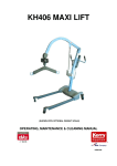
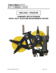
Issue
B
Date
29-03-10
Technical Manual
Completion Barrier Valve
Number:
0000030000
(patent applied for)
Description
The Caledyne Completion Barrier Valve (CBV) is a down-hole barrier
valve, which uses a ball to provide isolation between the upper and lower
completions.
The CBV may be opened remotely by applying tubing pressure cycles,
which actuate an opening mechanism at the top of the tool.
The CBV may be mechanically opened and closed with a shifting tool,
both before and after it is cycled open.
Key Benefits
Forces due to pressure differentials across the ball do not affect the
open/close mechanism or the remote opening module.
Smooth internal bore with a minimal number of locations for debris to
collect.
Remote opening module can be replaced for different actuation modules
or to vary the number of pressure cycles to open.
Multiple remote opening modules may be fitted without increasing the tool
length, giving full redundancy across this part of the tool.
Internal equalizing mechanism across the ball allows for reduced loads to
open the ball under high differential pressures.
Trigger mechanism can be independently tested prior to assembling
inside the valve.
Application
• Formation isolation when installing the upper completion.
• Packer setting valve
Certification
Consult your Caledyne representative.
©
2010
Page 1 of 9
www.caledyne.co.uk
Issue
B
Date
29-03-10
©
2010
Technical Manual
Page 2 of 9
Number:
0000030000
www.caledyne.co.uk
Issue
B
Date
29-03-10
Number:
Technical Manual
0000030000
Technical Specification
Parameter
A
B
C (min)
D (max)
E
F
G
H
I
J
Upper connection (note 1)
Lower connection (note 2)
Shifting Profile Size (note 3)
Pressure cycles to open (note 4)
Pressure rating across ball
Pressure rating through housing
Maximum opening pressure
Maximum threshold pressure
Minimum threshold pressure
Maximum overbalance
Temperature rating
Tensile rating (80ksi Material)
3-1/2”
x 7”
4-1/2”
x 7”
2674mm
(105.3”)
88.90mm
(3.500”)
71.73mm
(2.824”)
140.08mm
(5.515”)
88.90mm
(3.500”)
2013.3mm
(79.3”)
1135.6mm
(44.7”)
967.7mm
(38.1”)
628.5mm
(24.7”)
895.7mm
(35.3”)
3-1/2” 9.2#
NEW VAM
Pin
3-1/2” 9.2#
NEW VAM
Pin
2.812”
2744.4mm
(108.0”)
114.30mm
(4.500”)
82.47mm
(3.247”)
149.23mm
(5.875”)
114.30mm
(4.500”)
2050.2mm
(80.7”)
1165.6mm
(45.9”)
1002.7mm
(39.5”)
643.5mm
(25.3”)
925.7mm
(36.4”)
4-1/2”
15.1# NEW
VAM Pin
4-1/2”
15.1# NEW
VAM Pin
3.312”
10,000psi
172,500lbf
NEW VAM
Yield
(1.2 F of S)
Metallurgy Options
Standard Elastomer
Standard Ball Seat
WP Shifting Tool Size
Stinger Size
HEST Base Assembly Size
©
2010
2.875”
2.875”
2.200”
4-1/2”
x 7-5/8”
5-1/2”
x 9-5/8”
2744.4mm
3177.3mm
(108.0”)
(125.1”)
114.30mm
140.60mm
(4.500”)
(5.535”)
82.47mm
115.85mm
(3.247”)
(4.561”)
153.08mm
204.28mm
(6.027”)
(8.043”)
114.30mm
140.60mm
(4.500”)
(5.535”)
2050.2mm
2334.6mm
(80.7”)
(91.9”)
1165.6mm
1455.8mm
(45.9”)
(57.3”)
1002.7mm
1211.8mm
(39.5”)
(47.7”)
643.5mm
738.5mm
(25.3”)
(29.1”)
925.7mm
1095.8mm
(36.4”)
(43.1”)
4-1/2”
5-1/2” 23#
15.1# NEW NEW VAM
VAM Pin
Pin
4-1/2”
5-1/2” 23#
15.1# NEW NEW VAM
VAM Pin
Pin
3.312”
4.562”
1-20 cycles
5,000psi
5,000psi
10,000psi
10,000psi
4,000psi
3,000psi
1,000psi
500psi
0-150°C
294,000lbf
294,000lbf
398,000lbf
NEW VAM
NEW VAM
NEW VAM
Yield
Yield
Yield
(1.2 F of S) (1.2 F of S) (1.2 F of S)
AISI 4140-45 18-22Rc 80ksi
AISI 420 18-22Rc 80ksi 13%Cr
Inconel 718 (UNS N07718)
per NACE MR0175
Viton
PEEK compound
3.312”
3.312”
4.562”
3.312”
3.312”
4.562”
2.200”
2.200”
3.000”
Page 3 of 9
5-1/2” x
9-5/8”
(Large Bore)
3330.0mm
(131.1”)
140.60mm
(5.535”)
120.57mm
(4.747”)
212.8mm
(8.378”)
140.60mm
(5.535”)
2428.0mm
(95.6”)
1514.0mm
(59.6”)
1260.0mm
(49.6”)
768.0mm
(30.2”)
1140mm
(44.9”)
5-1/2” 23#
NEW VAM
Pin
5-1/2” 23#
NEW VAM
Pin
4.750”
10,000psi
398,000lbf
NEW VAM
Yield
(1.2 F of S)
4.750”
4.750”
3.000”
www.caledyne.co.uk
Issue
B
Date
29-03-10
Bill of Material
Description
Top Sub
Hydrostatic Housing
Outer Extension
Lower Coupling
Ball Housing
Lock Housing
Bottom Sub
Upper Hydrostatic Piston
Lower Hydrostatic Piston
Profile Sleeve
Key Housing
Locking Key
Snap Ring
Hyd Piston Interlock Key
Side Plate A
Side Plate B
Ball
Trunnion
Ball Seat Assembly
Transfer Sleeve
Snap Ring
Ball Seat
Cyclic Trigger Sub
No-Go Ring
Burst Disc Assembly
Adjuster Rod
¼” x ¼” Long Socket Head Set Screw
¼” UNC x ¼” Long Brass Shear Screw
Wave Spring
O-Ring Viton 70
Back Up Nitrile 90
O-Ring Viton 70
Back Up Nitrile 90
Tee Seal
Tee Seal
Tee Seal
¼” NPT Flush Plug
PLAA2528010A
Item
1
2
3
4
5
6
7
8
9
10
11
12
13
14
15
16
17
18
19
20
21
22
23
24
25
26
27
28
29
30
31
32
33
34
35
36
37
38
©
Technical Manual
2010
Page 4 of 9
Number:
0000030000
Qty
1
1
1
1
1
1
1
1
1
1
1
8
1
4
1
1
1
2
1
1
1
1
2
1
2
1
5
2
4
5
10
2
4
3
6
2
2
2
www.caledyne.co.uk
Issue
B
Date
29-03-10
Technical Manual
Number:
0000030000
Completion Barrier Valve – Locked Closed Position
Completion Barrier Valve – Cycled Open Position
Completion Barrier Valve – Recommissioned Locked Open
©
2010
Page 5 of 9
www.caledyne.co.uk
Issue
B
Date
29-03-10
Technical Manual
Number:
0000030000
WP Shifting Tool
Stinger
HEST
©
2010
Page 6 of 9
www.caledyne.co.uk
Issue
B
Date
29-03-10
Number:
Technical Manual
0000030000
Shipping/Storage Preparations
1. Ensure the valve is left open.
2. Fit thread protectors to the upper and lower connections.
3. Place the CBV in a suitable shipping crate. Ensure that Silica Gel is included in the crate.
Care and Maintenance
1.
2.
3.
Ensure thread protectors are fitted to the upper and lower connections at all times.
If the tool is being stored for more than 3 months, it should be stored vertically to help prevent the
internal o-rings taking a set.
The CBV is not field redressable. The tool should be returned to Caledyne or an approved
refurbishment facility for redress.
Operational Procedures
For installation of this item of equipment, refer to the appropriate operations manual, but these notes are given
as guidance.
The CBV is made up to the tubing string and run in hole. It may be installed either open or closed.
Gravel Packing
1.
2.
If carrying out gravel packing operations with the CBV, the shifting tool is normally positioned at the
end of the wash string, so the CBV is automatically closed when the wash pipe is withdrawn.
Once the valve is closed it may be pressure cycled open.
Pressure Cycle to Open
1.
2.
3.
Apply pressure to the tubing above the maximum threshold pressure as defined in the technical
specification. Hold this pressure for 5 minutes.
Bleed of pressure to a figure below the minimum threshold pressure as defined in the technical
specification. Hold this pressure for 5 minutes.
On the bleed down of the last cycle, the valve will open.
WP Shifting Tool
The WP Shifting tool can be used to shift the CBV open/closed on wash pipe, coil tubing, drill pipe or slickline.
1. Once the valve has been cycled open, the WP shifting tool is used to close it again. The WP shifting
tool is set up with shear out keys, so that the internal sleeves are repositioned.
2. Further open and close operations are done with the WP shifting tool set up with auto-release keys.
3. RIH to depth.
4. POOH and latch shifting profile.
5. Jar up to shift profile sleeve and close ball.
6. At full travel the shifting tool will auto-release.
7. POOH.
©
2010
Page 7 of 9
www.caledyne.co.uk
Issue
B
Date
29-03-10
Number:
Technical Manual
0000030000
Stinger
The Stinger is mounted on the bottom of an upper completion. The CBV is installed closed. When the upper
completion is installed the WP Shifting Tool will open the valve. On removal, the valve is automatically closed.
1.
2.
3.
4.
5.
6.
Fit Stinger to bottom of upper completion.
RIH to depth. The Stinger will pick up the lower shifting profile, opening the ball.
Continue RIH to depth.
To close the ball, POOH with upper completion.
The Stinger will pick up the upper shifting profile, closing the ball.
Continue POOH.
HEST
The High Expansion Shifting Tool (HEST) is a coil tubing deployed shifting tool allowing the operator to run
through restrictions above the CBV and expand the shifting keys out to locate the profile once at depth.
Nozzles at the bottom of the HEST also allow the operator to jet through the tool to clean up profiles prior to
shifting.
1.
2.
3.
4.
5.
6.
7.
Fit key set to suit CBV profile size into the HEST Base Assembly.
Make up the HEST to coiled tubing.
RIH to depth.
At depth begin jetting through HEST.
Increase pressure to value detailed in the HEST Technical Manual to inflate the keys.
Pick up the profile and shift the CBV ball open/closed.
POOH.
Contingency Measures
Pressure cycling does not open the valve.
1.
2.
3.
4.
5.
6.
7.
Use the WP Shifting Tool or HEST.
RIH and tag the ball.
POOH and latch shifting profile.
Jar down to shift profile sleeve and open ball.
At full travel the shifting tool will auto-release.
POOH.
Further open/close operations can then be carried out using a suitable CBV shifting tool.
Debris stops the valve from being mechanically opened.
1.
2.
3.
4.
5.
6.
7.
8.
9.
RIH with hydrostatic bailer or similar and remove debris from on top of the ball.
POOH.
Use the WP Shifting Tool or HEST.
RIH and tag the ball.
POOH and latch shifting profile.
If the profile cannot be latched repeat steps 1 to 6.
Once shifting profile is latched, Jar down to shift profile sleeve and open ball.
At full travel the shifting tool will auto-release.
POOH.
Paraffin build up in the Shifting Profiles (or similar)
©
2010
Page 8 of 9
www.caledyne.co.uk
Issue
B
Date
29-03-10
1.
2.
3.
4.
5.
6.
7.
8.
9.
10.
Number:
Technical Manual
0000030000
Fit key set to suit CBV profile size into the HEST Base Assembly.
Make up the HEST to coiled tubing.
RIH to depth.
At depth begin jetting through HEST with suitable solvent.
Travel in/out of hole jetting all profiles.
Increase pressure to value detailed in the HEST Technical Manual to inflate the keys.
Pick up the profile and attempt to shift the CBV ball open/closed.
If the sleeve is still unable to move repeat steps 4 to 6 until the sleeve can move freely.
Continue to shift ball open/closed a number of times to ensure free movement.
POOH.
Ball cannot be opened and must be milled.
The CBV ball has a centre dimple looking up hole when in the fully closed position which acts as a pilot for
milling operations. Mill selection and method should be determined with reference to best practices for
fishing and milling operations.
©
2010
Page 9 of 9
www.caledyne.co.uk