1
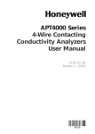
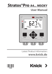
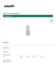
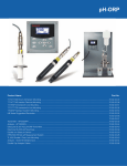
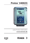
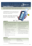
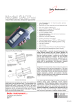
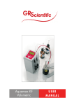
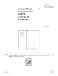
APT4000 Series Toroidal Conductivity Transmitters 70-82-03-42 3/01 Page 1 of 8 Specification Overview The Honeywell Analytical Process Transmitter (APT) 4000 Series transmitter continuously measures conductivity, chemical concentration and salinity in industrial processes within the chemical, food and dairy, pulp and paper, refinery, metals, and other industries. The APT4000’s NEMA 4X/IP65-rated enclosure is specifically designed to meet the measurement needs of Class I, Division 2 (non-incendive) and general-purpose areas. The transmitter can be used with Honeywell toroidal conductivity cells or electrically compatible sensors. The transmitter has a universal (20-253 V ac/dc, 45-65 Hz) power supply with one 4-20 mA output, two high/low alarm relays, a diagnostic relay, and a wash relay. enter MEAS CAL ALARM WASH CONF FM APPROVED CAL CONF ENTER APT4000 TC Description The Honeywell APT4000 series of transmitters offers the widest available selection of advanced features in a reliable and economical instrument. Reliability First Figure 1—APT4000 TC Transmitter Quick Problem Assessment The APT4000 has a large front display for quick recognition of process parameters and diagnostics even at a distance. Only the APT4000 employs visual feedback to quicken setup and maintenance times and to minimize errors made during calibrations. Visual feedback refers to pictograph type characters that appear on the display both to prompt and respond to operator and process changes. The advanced features of the APT4000 transmitter guarantee complete reliability. The APT4000 continuously monitors sensor and transmitter electronics and immediately displays diagnostic information at the onset of a problem. If an error or diagnostic is found, the transmitter will indicate the appropriate error code or pictograph (see Figure 2), blink a red LED and adjust the error Pictograph type characters also current to 22 mA if desired. A manual loop-back check is available to test the appear during problem conditions to report diagnostics for easy troubleintegrity of the 4-20 mA output. shooting. There is even a Sensoface pictograph that provides constant feedback to the operator on whether or not there is a problem with the cell. These easily learned and recognized symbols make the APT4000 an easyto-use instrument in any language. Foolproof Calibrations Each Honeywell conductivity cell has unique measuring characteristics when shipped from the factory. It is possible that these characteristics will vary slightly depending upon the installation as well. For optimum accuracy, a single-point calibration in a known conductivity solution should be performed when a new cell is installed. Further calibration adjustments are also available for enhanced accuracy in special applications. Sensing and Control, 11 West Spring Street, Freeport, Illinois 61032 Printed in U.S.A. © Copyright 2001—Honeywell 70-82-03-42 Page 2 Works with a Variety of Cells Fully Certified The inputs to the APT4000 Series include the Honeywell 5000TC toroidal conductivity cells, which feature a 1000 ohm Platinum RTD. In addition, a wide variety of other manufacturers’ toroidal conductivity cells are compatible. The area certification for the ATP4000 TC is FM Class I, Div. 2, Groups A-D (non-incendive). In addition, each transmitter comes standard with CE. Temperature Loop Current Conductivity Cell Check Display/Process Variable Alarm Setting Calibration Security Code Entry Interval/Response Time ON Sensoface OFF R Measurement Units Slope Conductivity Cell Data enter Zero Wait Hold State Active Continue with ENTER Bar for Instrument Status Figure 2—APT4000 TC Display Features Features • Large display with easy-to-read 0.75 inch measured value • Simple operator interface with basic pictographs • • • Easy installation with preassembled empty enclosure and plug-in terminals • Optical alarm signaling by blinking red LED Continuous diagnostics for monitoring calibration, cell health, and transmitter self-test • Manual loopback check for integrity of 4-20 mA output • • Application in Class I, Division 2 or • General Purpose areas • Wall, pipe or panel mounting • Integrated current source for simple checking of peripheral devices Quick Response Time (less than five seconds per step change) NEMA 4X, IP65 plastic enclosure Dedicated high/low alarm relay Applications The APT4000 TC transmitter is designed to meet the measurement needs of a number of industries, including: • Chemical • Food and Dairy • Pulp and Paper • Refinery • Metals 70-82-03-42 Page 3 Specifications Conductivity Input Conductivity Range 00.00 to 99.99 mS/cm, 000.0 to 999.9 mS/cm, 0000 to 1999 mS/cm Concentration Range NaCl HCl NaOH 0-26.3 % by wt (0 °C) 0-28.1 % by wt (100 °C) 0-17 % by wt (–20 °C) 0-17 % by wt (50 °C) 0-12 % by wt (0 °C) 0-22 % by wt (100 °C) H2SO4 H2SO4 HNO3 0-25 % by wt (–17 °C) 0-35 % by wt (110 °C) 95-99 % by wt (–10 °C) 95-99 % by wt (110 °C) 0-28 % by wt (–20 °C) 0-28 % by wt (50 °C) Salinity Range 0.0 % to 45.0 % (0 °C to 35 °C) Accuracy (1% of measured value) ± (0.02 mS/cm) ± (1 of least significant digit) Step Change Response Time Less than 5 seconds Diagnostics Sensocheck Polarization detection and monitoring of cable capacitance (can be switched off) Sensor Standarization - Entry of cell calibration factor with display of conductivity and temperature - Temperature probe adjustment Sensoface - Provides information on the electrode state via Sensocheck - Monitors asymmetry potential, slope, and response time during calibration Temperature Input Range Pt100/1000 Ω RTD, 100 K Ω Thermistor: –20.0 °C to +150.0 °C (+4 °F to +302 °F) Resolution Pt100/1000 Ω RTD, 100 K Ω Thermistor: 0.1 °C or 1 °F Accuracy Pt1000 Ω RTD: Pt100 Ω RTD: 100K Ω Thermistor: Temperature Compensation Automatic Compensation using Pt 100 Ω/1000 Ω RTD or 100 K ΩThermistor, or manual adjust Display LCD display 76 mm x 48 mm (3” x 1-7/8”) dimensions, 7-segment ± 0.5 °C ± 1 °C ± 0.5 °C below 100 °C; less than 1 °C above 100 °C Cond Value: character height 17 mm (0.66") , meas. symbol 10 mm (0.4") Temperature: character height 10 mm (0.4"), meas. symbol 7 mm (0.33") Sensoface with three states, 5 status bars, 16 pictographs / symbols, Red Alarm LED Security protection with four-digit mode codes to access calibration and configuration options Calibration Sensor Standardization Options Calibration by Cell Factor: 0.100 to 19.99 Calibration by Transfer Ratio: 1.00 to 99.99 Zero Point Air Calibration: ± 0.5 mS/cm offset (low conductivity measurements) Calibration by Standardizing Solution Test Mode Resistance measurement by use of fixed resistor temporarily inserted through the sensor bore. Area Certifications / Compliances Approvals FM Class I, Div. 2, Groups A-D Data Retention Parameters and calibration data > 10 years (EEPROM) RFI Suppression / Immunity to ESD To EN 50 081-1 and EN 50 081-2 Ambient Conditions Operation/Environmental temperature: (T4) –20 °C to +55 °C (–4 °F to +131 °F) (T6) –20 °C to +40 °C (–4 °F to +104 °F) Transport and Storage temperature: –20 °C to +70 °C (–4 °F to +158 °F) 70-82-03-42 Page 4 Supply/Output Output Current 0 mA or 4 mA to 20 mA current loop, 10 V floating Supply Voltage 20 V to 253 V ac/dc, 45 Hz to 65 Hz, 2 VA / 1.5 W Overrange 22 mA for error messages Current Error < 0.3 % of current value +0.05 mA Current Source 3.80 mA to 22.0 mA Output Characteristic Linear or Logarithmic Minimum Span LIN: 5 % of the selected range LOG: 1 decade Alarms/Relays Contacts Alarm minimum: SPST N/O (Hysteresis 0.2 % of measured range) Alarm maximum: SPST N/O (Hysteresis 0.2 % of measured range) Diagnostic contact: SPST N/C Wash contact: SPST N/O Maximal Current/Voltage AC: < 250 V / < 3A / < 750 VA DC: < 30 V/ < 3A / < 90 W Physical Enclosure Plastic enclosure made of PBT (polybutylene terephthalate) bluish-gray RAL 7031 Mounting Wall, Pipe, or Panel Mount Dimensions Height: 144 mm (5.67") Width: 144 mm (5.67") Depth: 105 mm (4.13") Protection NEMA 4X, IP65 Cable glands 3 breakthroughs for Pg 13.5 2 breakthroughs for NPT 1/2” or Rigid metallic conduit Weight Approximately 1 kg (2.2 lb.) 19 18 POWER 20-253 V 17 16 15 14 13 12 11 10 9 8 _ N.C. WASH N/O DIAGNOSTIC ALARM MAX N/C CONTACTS N/O ALARM MIN 7 + 0 (4) to 20 mA 6 5 T1 SHLD RD TEMP 4 3 2 1 HI GN LO YW LO BL HI WT N/O OUTPUT Figure 3—APT4000TC Terminal Assignments TOROIDAL CONDUCTIVITY SENSOR 70-82-03-42 Page 5 Model Selection Guide Reference 51-52-16-73 Instructions APT4000 Transmitter Offers: Power Requirements - Universal, 20 to 253V AC/DC 45 to 65 Hz Standard - NEMA 4X, IP65 Standard Approvals: General Purpose; also FM Class I, Div 2, Groups A-D Standard - All models CE Compliant High/Low Alarm Relays Three mounting types: (must be ordered separately) Panel Mount Kit Pipe/Wall Mount Kit Protective Hood (requires Pipe/Wall Mount Kit) Select the desired key number. The arrow to the right marks the selection available. Make one selection from Tables using the column below the proper arrow. A dot ( ) denotes unrestricted availability. Key Number _________ I - ___ KEY NUMBER Selection Availability Description of Measurement Type pH/ORP Toroidal (Electrodeless) Conductivity Contacting Conductivity APT 4000 PH APT 4000 TC APT 4000 CC TABLE I - Optional Equipment User’s Manual Future Future English E__ _0_ __0 NOTE: Mounting kit not included with APT4000. Accessory Parts Mounting Kits: Panel Mounting Kit Pipe/Wall Mounting Kit Protective Hood (requires pipe/wall kit) Instruction Manual - pH Instruction Manual - Toroidal (Electrodeless) Conductivity Instruction Manual - Contacting Conductivity Part Number 51205990-001 51205988-001 51205989-001 70-82-25-103 70-82-25-104 70-82-25-105 70-82-03-42 Page 6 Figure 4—Dimension Drawing for APT4000 and P/N 51205990-001 panel mounting kit 70-82-03-42 Page 7 Figure 5—Dimension Drawing for APT4000 with Wall or Pipe Mounting 70-82-03-42 Page 8 WARRANTY/REMEDY Honeywell warrants goods of its manufacture as being free of defective materials and faulty workmanship. Contact your local sales office for warranty information. If warranted goods are returned to Honeywell during the period of coverage, Honeywell will repair or replace without charge those items it finds defective. The foregoing is Buyer’s sole remedy and is in lieu of all other warranties, expressed or implied, including those of merchantability and fitness for a particular purpose. Specifications may change without notice. The information we supply is believed to be accurate and reliable as of this printing. However, we assume no responsibility for its use. While we provide application assistance personally, through our literature and the Honeywell web site, it is up to the customer to determine the suitability of the product in the application. For more information, contact Honeywell sales at (800) 343-0228. Sensing and Control Honeywell 11 West Spring Street Freeport, IL 61032 70-82-03-42 0301 Printed in USA www.honeywell.com/sensing