1
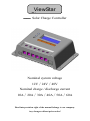
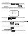
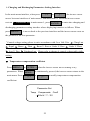
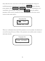
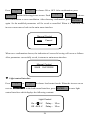
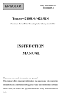
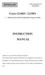
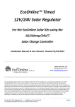
EPSOLAR ViewStar series —— Solar Charge Controller INSTRUCTION MANUAL Thank you very much for selecting our product! This manual offers important information and suggestions with respect to installation, use and troubleshooting, etc. Please read this manual carefully before using the product and pay attention to the safety recommendations in it. PATENTED PRODUCT, COUNTERFEITING NOT ALLOWED! ViewStar Star —— Solar Charge Controller Nominal system voltage 12V∕24V∕48V Nominal charge / discharge current 10A∕20A∕30A∕40A∕50A∕60A Final interpretation right of the manual belongs to our company. Any changes without prior notice! Contents 1 Important Safety Information ....................................................................................... 1 2 General Information..................................................................................................... 2 2.1 Product Overview ........................................................................................... 2 2.2 Product Features .............................................................................................. 3 2.3 Optional Accessories ....................................................................................... 5 3 Installation Instructions ................................................................................................ 6 3.1 Mounting ........................................................................................................ 6 3.2 Wiring............................................................................................................. 8 4 Operation................................................................................................................... 11 4.1 PWM Technology ......................................................................................... 11 4.2 Battery Charging Information ........................................................................ 11 4.3 HMI Interface ............................................................................................... 13 4.4 Operation and Displaying of Controller ......................................................... 15 System Monitor Interface ......................................................... 17 Device Setting Interface............................................................ 20 Charging and Discharging Parameters Setting Interface ............ 22 Load Control Interface .............................................................. 25 Nominal Parameter Interface .................................................... 31 Factory Reset Interface ............................................................. 32 5 Protection, Troubleshooting and Maintenance ............................................................ 34 5.1 Protection ...................................................................................................... 34 5.2 Troubleshooting ............................................................................................ 35 5.3 Maintenance .................................................................................................. 38 6 Warranty ................................................................................................................... 39 7 Technical Specifications ............................................................................................ 40 1 Important Safety Information Save These Instructions This manual contains important safety, installation and operating instructions. The following symbols are used throughout this manual to indicate potentially dangerous conditions or mark important safety instruction, please take care when meeting following symbols. WARNING: Indicates a potentially dangerous condition. Use extreme caution when performing this task. CAUTION: Indicates a critical procedure for safe and Proper operation of the controller. General Safety Information Read all of the instructions and cautions in the manual before beginning installation. There are no user serviceable parts inside the controller. Do not disassemble or attempt to repair it. Install external fuses/breakers as required. Disconnect the solar module and fuse/breakers near to battery before installing or adjusting the controller. Do not allow water to enter the controller. Confirm that power connections are tightened to avoid excessive heating from loose connection. 1 2 General Information Thank you for selecting ViewStar series solar charge controller that adopts the most advanced digital technique, displays on the LCD and operates fully automatically. The Pulse Width Modulation (PWM) battery charging and the unique control technology can greatly increase the lifetime of battery. It has various unique functions and easy to use. 2.1 Product Overview The controller is for off-grid solar system, and protects the battery from being over charged by the solar module and over discharged by the loads. The charging process has been optimized for long battery life and improved system performance. The comprehensive self-diagnostics and electronic protection functions can prevent damage from installation mistakes or system faults. Features: 32 bit MCU with high speed and high performance 12 bit A/D high-precision sampling to ensure accuracy Excellent EMC design Nominal system voltage automatic recognition High efficient Series PWM charging, increase the battery lifetime and improve the solar system performance Use MOSFET as electronic switch, without any mechanical switch Widely used, automatically recognize day/night Adopt graphics dot-matrix LCD screen and HMI (human-machine interface) with 4 buttons, integrated menu displaying and operation Humanized design of browser interface, undertake every operating conveniently Full control parameters setting and modification, diversified load control mode Gel, Sealed and Flooded battery type option Adopt temperature compensation, correction algorithm for charging and discharging parameters automatically and improve the battery lifetime Electronic protection: Overheating, over charging, over discharging, overload, and short circuit. Reverse protection: any combination of solar module and battery 2 2.2 Product Features VS1024(N) / VS2024(N) 2 3 4 1 5 10 9 8 7 6 VS2048(N) / VS30**(N) / VS40**(N) / VS50**(N) / VS60**(N) 1 3 2 4 5 6 9 8 7 10 3 1 – Local temperature sensor It is used for acquisition of ambient temperature to undertake temperature compensation of charging and discharging parameters, when the remote temperature sensor is not connected 2 – Fault LED indicator An LED indicator that shows faults of solar system 3 – Charging LED indicator An LED indicator that shows charging status 4 – Liquid crystal display (LCD) Monitoring interface for solar system parameters 5 – Combined-type buttons 4 combined-type buttons accomplish all operations to controller 6 – Communication interface Connect remote displaying unit MT-100 (Optional Accessories) 7 – Load terminals Connect loads 8 – Battery terminals Connect batteries 9 – Solar module terminals Connect solar modules 10 – Remote temperature sensor interface Connect remote temperature sensor TS-R (Optional Accessories) to acquire of ambient temperature for undertaking temperature compensation of charging and discharging parameters, when it is in connection. 4 2.3 Optional Accessories 1. Remote Meter(Model:MT-100) The digital Remote Meter displays system operating information, error indications, and self-diagnostics read-out. Information is displayed on a backlit LCD display. The large numerical display and icons are easy to read and large buttons make navigating the meter menus easy. The meter can be flush mounted in a wall or surface mounted using the mounting frame (included). The MT-100 is supplied with 1.5m of cable and a mounting frame. The MT-100 connects to the RJ45 port on the VS. 2. Remote temperature sensor (Model:TS-R) Acquiring of ambient temperature for undertaking temperature compensation of charging and discharging parameters, the standard length of the cable is 2m (can be customized if want longer or shorter). The TS-R connects to the 2ERJ—3.81 port on the VS. 5 3 Installation Instructions 3.1 Mounting Read through the entire installation section first before beginning installation. Be very careful when working with batteries. Wear eye protection. Have fresh water available to wash and clean any contact with battery acid. Uses insulated tools and avoid placing metal objects near the batteries. Explosive battery gasses may be present during charging. Be certain there is sufficient ventilation to release the gasses. Avoid direct sunlight and do not install in locations where water can enter the controller. Loose power connections and/or corroded wires may result in resistive connections that melt wire insulation, burn surrounding materials, or even cause fire. Ensure tight connections and use cable clamps to secure cables and prevent them from swaying in mobile applications. Use with Gel, Sealed or Flooded batteries only. Battery connection may be wired to one battery or a bank of batteries. The following instructions refer to a singular battery, but it is implied that the battery connection can be made to either one battery or a group of batteries in a battery bank. Select the system cables according to 3A/mm2 current density NOTE: When mounting the controller, ensure free air through the controller heat sink fins. There should be at least 6 inches (150 mm) of clearance above and below the controller to allow for cooling. If mounted in an enclosure, ventilation is highly recommended. WARNING: Risk of explosion! Never install the controller in a sealed enclose with flooded batteries! Do not install in a confined area where battery gassed can accumulate. 6 Step 1: Choose Mounting Location Locate the controller on a vertical surface protected from direct sun, high temperature, and water. And make sure good ventilation. Step 2: Check for clearance Place the controller in the location where it will be mounted. Verify that there is sufficient room to run wires and that there is sufficient room above and below the controller for air flow. 150mm(5.9inches) Warm air 150mm(5.9inches) Cool air Step 3: Mark Holes Use a pencil or pen to mark the four (4) mounting hole locations on the mounting surface. Step 4: Drill Holes Remove the controller and drill 4mm holes in the marked locations. Step 5: Secure Controller Place the controller on the surface and align the mounting holes with the drilled holes in step 4. Secure the controller in place using the mounting screws. 7 3.2 Wiring NOTE: A recommended connection order has been provided for maximum safety during installation. NOTE: There are two types of the controller: common positive controller and common negative controller. CAUTION: Don’t connect the loads with surge power exceeding the ratings of the controller. CAUTION: For mobile applications, be sure to secure all wiring. Use cable clamps to prevent cables from swaying when the vehicle is in motion. Unsecured cables create loose and resistive connections which may lead to excessive heating and/or fire. WARNING: Risk of explosion or fire! Never short circuit battery positive (+) and negative (-) or cables. WARNING: Risk of electric shock! Exercise caution when handling solar wiring. The solar module(s) high voltage output can cause severe shock or injury. Be careful operation when installing solar wiring. Before battery is connected, make sure that voltage of battery is higher than 9V so as to start the controller. If nominal system voltage is 24V, make sure that voltage of battery is no less than 18V; if nominal system voltage is 48V, make sure that voltage of battery is no less than 42V. The nominal system voltage can only be automatically identified when controller is started for the first time. 8 Controller’s load terminals can be connected to DC electric equipments whose nominal operation voltage is the same as nominal voltage of battery. The controller supplies power to loads with battery voltage. It is suggested that positive pole or negative pole of battery and loads should be connected to a safety device, whose operation current is not twice lower than nominal charging or discharging current. Do not switch on the safety device while it is being installed. Switch on the safety device after the wiring is confirmed to be correct. CAUTION: On occasions that controller must be connected to the ground. For common positive controller, the positive pole must be connected to the ground, on the contrary, the negative pole must be connected to the ground for common negative controller. ﹡ Wire conductor length: VS1024(N) :7mm VS20**(N) :13mm VS30**(N) :10mm VS40**(N) / VS50**(N) / VS60**(N) :14mm 9 Step 1: Wiring and switching on After solar system is wired, check carefully all wirings so as to make it clear whether all 6 terminals are correctly connected and tightened. According to the order of switching on in the chart, battery first, loads second and solar module third successively to avoid nominal system voltage identification error. Solar Module 3 Load + - + - + Fuse Fuse 2 1 Battery Step 2: Confirming power on When controller starts up, liquid crystal display (LCD) displays initialization interface and 2 indicator lamps will be lightened once, check if it is correct. If there are no above procedures, refer to section 5 for troubleshooting. 10 4 Operation 4.1 PWM Technology (Series Pulse Width Modulation) The controller adopts the advanced series pulse width modulation (PWM) charging mode. With range of 0-100%, it can charge the battery quickly and stably under any condition of solar photovoltaic system. PWM charging mode use automatic conversion duty ratio pulses current to charge the battery. The battery can be fully charged safety and rapidly with the pulse current. Intermissions make some oxygen and hydrogen generated by chemical reaction chemically combined again and absorbed. It can eliminate concentration polarization and ohm polarization naturally and reduce the internal pressure of the battery so that the battery can absorb more power. Pulse current charging mode makes battery have more time to react, which reduces the gassing volume and makes battery improve the acceptance rate of charging current. 4.2 Battery Charging Information · Bulk Charge In this stage, the battery voltage has not yet reached boost voltage and 100% of available solar power is used to charge the battery. 11 · Boost Charge When the battery has recharged to the Boost voltage setpoint, constant- current regulation is used to prevent heating and excessive battery gassing. The Boost stage remains 120 minutes and then goes to Float Charge. Every time when the controller is powered on, if it detects neither over discharged nor overvoltage, the charging will enter into boost charging stage. · Float Charge After the battery is fully charged in Boost voltage stage, the controller reduces the battery voltage to Float voltage set point. When the battery is fully recharged, there will be no more chemical reactions and all the charge current transmits into heat and gas at this time. Then the controller reduces the voltage to the floating stage, charging with a smaller voltage and current. It will reduce the temperature of battery and prevent the gassing, also charging the battery slightly at the same time. The purpose of Float stage is to offset the power consumption caused by self consumption and small loads in the whole system, while maintaining full battery storage capacity. In Float stage, loads can continue to draw power from the battery. In the event that the system load(s) exceed the solar charge current, the controller will no longer be able to maintain the battery at the Float setpoint. Should the battery voltage remains below the boost reconnect charging voltage, the controller will exit Float stage and return to Bulk charge. · Equalize Charge WARNING: Risk of explosion! Equalizing flooded battery can produce explosive gases, so well ventilation of battery box is necessary. NOTE: Equipment damage! Equalization may increase battery voltage to the level damaging to sensitive DC loads. Ensure that all load allowable input voltages are greater than the equalizing charging set point voltage. 12 NOTE: Equipment damage! Over-charging and excessive gas precipitation may damage the battery plates and activate material shedding on them. Too high an equalizing charge or for too long may cause damage. Please carefully review the specific requirements of the battery used in the system. Certain types of batteries benefit from periodic equalizing charge, which can stir the electrolyte, balance battery voltage and complete chemical reaction. Equalizing charge increases the battery voltage, higher than the standard complement voltage, which gasifies the battery electrolyte. Every month 28th solar controller will engender equalize charging stage. It will remain 120mins when equalize stage is constant, or it will remain 180mins when equalize charging accomplishes off and on. Equalize charge and boost charge are not carried out constantly in a full charge process to avoid too much gas precipitation or overheating of battery. 4.3 HMI Interface Charging indicator Fault indicator LCD WELCOME VERSION 1.1 ! MENU/← ↑/ + 13 ↓/ - ENTER/→ ■ Buttons instruction: MENU/← :Menu / Cursor left button ↑/ + :Cursor up / Number add button ↓/ - :Cursor down / Number reduce button ENTER/→ :Enter / cursor right button Charging indicator GREEN ON whenever sunlight is available for battery charging, Charging LED indicator Table 4-1 Color Indicator Charging Status Green On Solid Charging Fault indicator When the following cases occur, fault indicator red flashing: Solar module: Over current, Measure error of voltage, Short of counter-attack MOS-I, Short of charging MOS-C, MOS-I or MOS-C disconnection or MOS break in control section; Battery: Over voltage, Measure error of voltage, Over temp; Load: Over load, Short, Short of discharging MOS, Measure error of voltage; Device: Over temp. For trouble shooting, refer to chapter 5. 14 Fault LED indicator Color Table 4-2 Indicator Charging Status PV:OverCurrent、Measure Err、 MOS-I Short、MOS-C Short、 MOS Break BATT:OVD、Error、OverTemp Red Flashing LOAD:Overload、Short、 MOS Short、Error DEVICE:OverTemp 4.4 Operation and Displaying of Controller Load work mode 1. Dusk to Dawn When solar module voltage goes below the point of NTTV (Night Time Threshold Voltage) at sunset, the controller will recognize the starting voltage and turn on the load after configurable delay time. When solar module voltage goes above point of DTTV (Day Time Threshold Voltage), the solar controller will recognize the starting voltage and turn off the load after configurable delay time. 2. Light ON + Timer When solar module voltage goes below the point of NTTV (Night Time Threshold Voltage) at sunset; the solar controller will recognize the starting voltage and turn on the load after configurable delay time. The load will be on for several hours which users set. 3. Timer The mode includes single and double time intervals. Set the starting and ending time for each time interval and controller works according to the set time interval. 4. Manual mode This mode is to turn ON and OFF the load by manual. 15 Operation and displaying of controller Initialization Interface When controller is powered on, it turns into initialization, refer to the following picture: WELCOME VERSION 1.1 Main Menu Interface When controller is initialized, it is automatically turned into monitoring interface. Press button MENU/← to turn into main menu 1 interface which displays the following contents: 1.Monitoring Press the button ↓/ - 2.Device Set Inverse cursor showing 3.Parameter Set the contents can be 4.Load Set operated continuously, entering into main menu 2 interface which displays the following contents: 5.Rated Value 6.Factory Reset 16 System Monitor Interface ↑/ + In the main menu interface, when press or ↓/ - , the inverse cursor moves between main menu 1 and main menu 2.When the inverse cursor rests at 1.Monitoring in the main menu 1 interface, press ENTER/→ to enter into the system monitoring interface which displays contents as follows. Press ↑/ + or ↓/ - to circularly display every real-time parameters interface. ▼Solar array voltage and current The interface shows real-time voltage and current of solar module. PV 14.5V 7.2A ▼ Battery voltage and current Press ↓/ - to enter into the following interface which shows real-time voltage and current of battery. Negative indication with current, it means that the battery is in discharging status. Positive indication with current, it means that the battery is in charging status. BATT 12.5V —5.5A ▼ Battery temperature and battery temperature compensation coefficient Press ↓/ - to enter into the following interface which indicates real-time temperature of battery and battery temperature compensation coefficient. TEMP 25.6 ℃ C: -3.5mV / ℃ / 2V 17 ▼ Load voltage and current Press ↓/ - and then enter into the following interface which indicates real-time voltage and current of loads. LOAD 12.5V 5.5A ▼ Real-time clock and imaging system status Press ↓/ - and enter into the following interface which indicates real-time clock and imaging system status. If choose the manual mode with loads, press ENTER/→ in the interface, which can control loads on and off. Real-time clock 12 : 24 : 23 ■ Introductions to system status icons: :Day :Night :Charging :Normal :LVD :Normal :UVW :LVD :ON :OFF ﹡ Icons indicating battery charging are dynamic effects. 18 ▼ System status Press ↓/ - and enter into the following interface which indicates system status. PV : Disconnect BATT : NoCharge / Normal LOAD : On DEVICE : Normal PV status: Connect Disconnect Over Current MOS-I Short Measure Err MOS-C Short MOS Break BATT status: Equalize Boost NoCharge LVD UVW OVD Error Off OverLoad Error MOS Short Normal Float OverTemp LOAD status: On Short DEVICE status: Normal OverTemp ﹡ When fault with inverse cursor appears, if the fault still exists 2 minutes after no button-pressing operation, it is automatically skipped into this page. 19 Device Setting Interface In the main menu interface, press ↑/ + ↓/ - or , the inverse cursor moves between interfaces of main menu 1 and main menu 2. When the inverse cursor rests on 2.Device Set in the main menu interface 1, press ENTER/→ to enter into system setting interface which displays the following contents. When setting in this interface, real time clock will stop running. Please correct real time clock again after parameters are changed. Device Set Date : 12 – 05 - 2011 Time : 12 : 24 : 23 Backlight : 10 Mins In the interface, press MENU/← or ENTER/→ , the inverse cursor moves among every parameter. When MENU/← is continuously pressed, the inverse cursor moves back to main menu interface. When inverse cursor rests at some parameter, the contents of the parameter can be modified. When modify date and time information, press to increase the figure and press ↓/ - to reduce figure. When modify LCD backlight working mode, push ↑/ + or ↓/ - ↑/ + , the automatic switch on-and-off time of LCD backlight can be set between 00~30 minutes. Only when the inverse cursor moves to option of LCD backlight, can the modified parameters information can be saved. Press ENTER/→ , then the following picture appears. Press button ↑/ + or ↓/ - After choosing confirmation, press to choose save confirmation or save cancelation. ENTER/→ again, the modified parameters will be saved or cancelled. If choose save cancellation, the inverse cursor returns to main menu interface. Automatic default off time of LCD backlight is one (1) minute. 20 Device Set Date : 12 – 05 - 2011 Save Cancel Time : 12 : 24 : 23 Backlight : 10 Mins If save confirmation is chosen, the system will automatically check the validity of parameters. If the parameters are reasonably set, the indication of successful saving will occur as follows. After parameters successfully saved, it returns to main menu interface. Device Set Date : 12 – 05 - 2011 SAVE SUCCESS! Time : 12 : 24 : 23 Backlight : 10 Mins If the following prompt occurs when it is being saved, it indicates failure of saving and parameters setting is illegal. So please verify parameters information. Device Set Date : 12 – 05 - 2011 ILLEGAL PARAM! Time : 12 : 24 : 23 Backlight : 10 Mins 21 Charging and Discharging Parameters Setting Interface ↑/ + In the main menu interface, when press or ↓/ - , the inverse cursor moves between interfaces of main menu 1 and main menu 2. when the inverse cursor rests on 3.Parameter Set in main menu 1, press ENTER/→ to enter into charging and discharging parameters setting interface whose displaying interface as follows. When press MENU/← , it moves back to the previous interface and the inverse cursor rests on the position of the first parameter. ﹡ Control voltage setting please in strict accordance with Over Volt. Disc > Charg Lmt > Equal > Boost > Float > Boost V. Rect or Under V. Rect > Under V. Warn > Low V. Disc > Discharg Lmt , Please refer to chapter 6 control voltage table while setting. ▼ Temperature compensation coefficient Press MENU/← or ENTER/→ , then the inverse cursor moves among every parameters. When MENU/← is continuously pressed, the inverse cursor returns to the main menu. Press ↑/ + or ↓/ - to modify temperature compensation coefficient. Parameter Set Temp Compensate -05.0mV / ℃ / 2V 22 Coeff ▼ Control parameters interface Press ENTER/→ continuously and the inverse cursor will enter into the control parameters interface. Press ↑/ + or ↓/ - to modify the following control parameters. Parameter Set Over Volt. Disc : 16.0V Charg Lmt : 15.5V Over Volt. Rect : 15.0V Parameter Set If battery type is GEL, Equal Chrg : 14.6V the parameters cannot be Boost Chrg : 14.4V modified. Float Chrg : 13.8V Parameter Set Boost V. Rect : 13.2V Low V. Rect : 12.6V Under V. Rect : 12.2V Parameter Set Under V. Warn : 12.0V Low V. Disc : 11.1V Discharg Lmt : 10.8V 23 Only when the inverse cursor moves to the option of discharging limit voltage, the modified parameters information can be saved. Press ENTER/→ and the following picture appears. Press ↑/ + or ↓/ - to choose save confirmation or save cancellation. After choosing confirmation, press ENTER/→ again, the modified parameters will be saved or cancelled. If choose save cancellation, the inverse cursor returns to main menu interface. Parameter Set Under V. Warn : 12.0V Save Cancel Low V. Disc : 11.1V Discharg Lmt : 10.8V When save confirmation chosen and if the parameters are set reasonably, the indication of successful saving will occur as follows. After parameters successfully saved, it returns to main menu interface. Parameter Set Under V. Warn : 12.0V SAVE SUCCESS! Low V. Disc : 11.1V Discharg Lmt : 10.8V 24 Load Control Interface In the main menu interface, when press ↑/ + or ↓/ - , the inverse cursor moves between the interfaces of main menu 1 and main menu 2. When the inverse cursor rests on 4.Load Set in main menu 1, press ENTER/→ and enter load control interface with the following contents displayed. Manual Light On / off Light On + Timer Time ﹡When set light control threshold voltage, it should meet the requirement : DTTV (Day Time Threshold Voltage) >= NTTV (Night Time Threshold Voltage)+1V. Notice: Adjust DTTV (OFF) first and then NTTV (ON). ▼ Manual control interface Press ↑/ + or ↓/ - to choose load control mode. When the inverse cursor rests on Manual in the load control interface, press ENTER/→ to enter manual control interface which displays the following contents. In manual control mode, the load will work as previous setting when restart the controller. Manual Control OFF ON 25 Press ↑/ + or ↓/ - to choose ON or OFF. After confirmation, press ENTER/→ and the following picture occurs. Push ↑/ + or ↓/ - to choose save confirmation or save cancellation. After choosing confirmation, press ENTER/→ again. So the modified parameters will be saved or cancelled. When it is cancelled, the inverse cursor moves back to the main menu interface. Manual Control Save Cancel OFF ON When save confirmation chosen, the indication of successful saving will occur as follows. After parameters successfully saved, it returns to main menu interface. Manual Control SAVE SUCCESS! OFF ON ▼ Light control interface Press ↑/ + or ↓/ - to choose load control mode. When the inverse cursor rests on Light On / off in the load control interface, press ENTER/→ to enter light control interface which displays the following contents. Light Control On : 05.0 V Delay :10 m Off : 06.0 V Delay :10 m 26 When press MENU/← or ENTER/→ , the inverse cursor moves among every parameters. When MENU/← is continuously pressed, it moves back to main menu interface and press or ↑/ + to modify every parameters. Only when ↓/ - the inverse cursor rests on option of light control off delay, can modification of the parameters be saved. When modification is confirmed, press ENTER/→ , and the following picture appears. Press ↑/ + or ↓/ - to choose save confirmation or save cancellation. After choosing confirmation, press ENTER/→ again, and the modified parameter can be saved or cancelled. When save cancellation is chosen, the inverse cursor moves back to the main menu interface. Light Control On : 06.0 V Save Delay :10 m Cancel Off : 05.0 V Delay :10 m When save confirmation chosen, the indication of successful saving will occur as follows. After parameters successfully saved, it returns to main menu interface. Light Control On :SAVE 06.0 V SUCCESS! Delay :10 m Off : 05.0 V Delay :10 m 27 ▼ Light control + timer control interface ↑/ + Press ↓/ or to choose load control mode. When the inverse cursor rests on Light On + Timer in the load control interface, press ENTER/→ to enter into light control plus time control interface. Light Timer Control On : 05.0 V Delay :10 m Off : 06.0 V Delay :10 m Work Time : 10 : 00 : 00 When press MENU/← or ENTER/→ , the inverse cursor moves among every parameters. When MENU/← is continuously pressed, it moves back to main menu interface and press or ↑/ + ↓/ - to modify every parameters. Only when the inverse cursor rests on“Work Time” interface, can modification of the parameters be saved. When modification is confirmed, press ENTER/→ ,and the following picture appears. Press ↑/ + or ↓/ - to choose save confirmation or save cancellation. After choosing confirmation, Press ENTER/→ again, and the modified parameter can be saved or cancelled. When save cancellation is chosen, the inverse cursor moves back to the main menu interface. Light Timer Control On : 06.0 V Delay :10 m Save Cancel Off : 05.0 V Delay :10 m Work Time : 10 : 00 : 00 28 When save confirmation chosen, the indication of successful saving will occur as follows. After parameters successfully saved, it returns to main menu interface. Light Timer Control On : 06.0 V Delay :10 m SAVE SUCCESS! Off : 05.0 V Delay :10 m Work Time : 10 : 00 : 00 Notes: when the “OFF” time is later than local sunrise time, the controller will turn off the load output at the sunrise time, which shows light control first! ▼ Time control interface Press ↑/ + ↓/ - or to choose time control mode. When the inverse cursor rests on Time in the time control interface, press ENTER/→ to enter into time control interface. When press MENU/← or ENTER/→ , the inverse cursor moves among every parameters. When MENU/← is continuously pressed, it moves back to main menu interface and press ↑/ + or ↓/ - to modify all parameters of time interval 1. Time Control 1 On Time : 07 : 20 : 00 Off Time : 15 : 00 : 00 When ENTER/→ is continuously pressed, it will enter into the following interface. When press MENU/← or ENTER/→ , the inverse cursor moves among every parameters. Press ↑/ + or to modify all parameters of time interval 2. ↓/ 29 When choose Double as time control mode, it is double time interval control. Time Control 2 On Time : 16 : 30 : 00 Off Time : 06 : 00 : 00 Double Single ﹡ In the double time work mode, time2 could not be the same as time 1 when Setting. When choose Single as time control mode, it is single time interval control and only parameters of time interval 1 can be modified. The interface is as follows: Time Control 2 On Time : -- : -- : -Off Time : -- : -- : -Double Single After confirmed, press ENTER/→ , and the following picture appears. Press ↑/ + or ↓/ - choosing confirmation, press to choose save confirmation or save cancellation. After again, and the modified parameters can be ENTER/→ saved or cancelled. When save cancellation is chosen, the inverse cursor moves back to the main menu interface. Time Control 2 On Time : 19 : 20 : 00 Save Cancel Off Time : 07 : 00 : 00 Double 30 Single When save confirmation chosen, the indication of successful saving will occur as follows. After parameters successfully saved, it returns to main menu interface. Time Control 2 On Time : 19 : 20 : 00 SAVE SUCCESS! Off Time : 07 : 00 : 00 Double Single Nominal Parameter Interface ↑/ + In the main menu interface, when press or ↓/ - , the inverse cursor moves between the interfaces of main menu 1 and main menu 2. When the inverse cursor rests on 5.Rated Value in the main menu 1 interface, press ENTER/→ and enter into nominal parameter interface with the following contents displayed. In the interface, battery type and capacity can be modified and the modification range is 1-999AH. Press ↑/ + or ↓/ - to modify the relevant parameters. Rated Value Batt : 12.0 V 070AH Load : 10.0A PV : 10.0A Type : Seal Gel Flood After confirmed, press ENTER/→ and the following picture appears. Press ↑/ + or ↓/ - choosing confirmation, press to choose save confirmation or save cancellation. After ENTER/→ again, and the modified parameters can be saved or cancelled. When save cancellation is chosen, the inverse cursor moves back to the main menu interface. 31 Rated Value Batt : 12.0 V Save Cancel Load : 10.0A PV : 10.0A Type : Seal Gel Flood When save confirmation chosen, the indication of successful saving will occur as follows. After parameters successfully saved, it returns to main menu interface. Rated Value Batt : 12.0 V SAVE SUCCESS! Load : 10.0A PV : 10.0A Type : Seal Gel Flood Factory Reset Interface In the main menu interface, when press ↑/ + or ↓/ - , the inverse cursor moves between the interfaces of main menu 1 and main menu 2. When the inverse cursor rests on 6.Factory Reset in the interface of main menu 1, press ENTER/→ and enter into factory reset interface with the following contents displayed. Press ↓/ - to choose whether recover to factory reset. Factory Reset NO YES 32 ↑/ + or After confirmed, push ENTER/→, and the following picture appears. Press ↑/ + or ↓/ - choosing confirmation, press to choose save confirmation or save cancellation. After ENTER/→ again, and the modified parameters can be saved or cancelled. When save cancellation is chosen, the inverse cursor moves back to the main menu interface. Factory Reset OK Cancel NO YES When save confirmation chosen, the indication of successful saving will occur as follows. After parameters successfully saved, it returns to main menu interface. Factory Reset RESET SUCCESS! NO YES 33 5 Protection, Troubleshooting and Maintenance 5.1 Protection · PV Array Short Circuit If PV array short circuit occurs, clear it to resume normal operation. · Load Overload If the load current exceeds the maximum load current rating, the controller will disconnect the load. Overloading must be cleared up through reapply power or pressing the setting button. · Load Short Circuit Fully protected against load wiring short-circuit. After one automatic load reconnect attempt, the fault must be cleared by reapply power or pressing the setting button. · PV Reverse Polarity Fully protection against PV reverse polarity, no damage to the controller will result. Correct the mistake connection to resume normal operation. · Battery Reverse Polarity Fully protection against battery reverse polarity, no damage to the controller will result. Correct the mistake connection to resume normal operation. · Damaged Local Temperature Sensor If the temperature sensor short-circuited or damaged, the controller will be charging or discharging at the default temperature 25℃ to prevent the battery damaged from overcharging or over discharged. · Overheating Protection If the temperature of the controller heat sink exceeds 85C, the controller will automatically start the overheating protection. It recover after it drops to 80C. · High Voltage Transients PV is protected against high voltage transients. In lightning prone areas, additional external suppression is recommended. 34 5.2 Troubleshooting Trouble Shooting Table 5-1 Faults Possible reasons Troubleshooting Charging LED indicator PV Check off during daytime when array connections are correct and tight. sunshine falls on PV disconnection that PV and battery wire modules properly. the PV of monitoring interface shows Disconnect. Charging circuit is off and Charging the current PV of interface monitoring shows Over Current. more Please check whether solar panel array is than match with nominal parameters of controller; When Charging current reaches nominal 1.05-1.25 times, 1.25-1.5 times and 1.5 current value times more than nominal value, controller will automatically close loads in 60 seconds, 5 seconds and 1 second, respectively. Controller is automatically circularly activated so as to reconnect charging circuit. Every reactivating is 60 seconds delayed, but not limits on number of times. Charging and discharging MOS-I or Please restart controller, if the fault still circuit is off and the PV of MOS-C is exists, immediately switch off charging monitoring interface shows damaged. Measure and Err 、 MOS-I discharging circuit; contact the supplier to make maintenance. Short、MOS-C Short、MOS Break. Loads do not work and the Battery The BATT over automatically discharged charged. of monitoring interface shows LVD. 35 controller cut off recovered the when output, fully Charging and discharging Battery circuit is off and the BATT voltage of monitoring over Measure and judge if the voltage of battery is too high, and switch off the interface wiring of solar array. shows OVD. Charging and discharging Operating circuit is off and the BATT ambient When operating ambient temperature or of temperature battery temperature reaches more than (local 85℃, controller will automatically cut off monitoring interface shows Over Temp. temperature sensor) or input and output circuit. When the temperature is less than 75℃, battery controller will automatically recover the temperature connection of input and output circuit. (remote temperature sensor) over temperature Charging and discharging Battery circuit is off and the BATT voltage Please restart controller, if the fault still of inspection exists, immediately cut off charging and shows Error. fault discharging circuit and contact the Discharging circuit is off Load and monitoring interface supplier to make maintenance. power surpasses Please reduce the number of electric monitoring interface shows nominal equipments. When load power reaches OverLoad. power 1.05-1.25 times, 1.25-1.5 times and 1.5 the LOAD of times more than nominal value, controller will automatically close loads in 60 seconds, 5 seconds and 1 second, respectively. It is reactivated after delayed 5 seconds for the first time, 10 seconds for the second time, 15 seconds for the third time, 20 seconds for the fourth time and 25 seconds for the fifth time. If over 5 36 times, push the key ENTER and controller recover output after 10 seconds. In the process of 5-time reactivation, if it is recovered manually, the 5-time reactivation will be circulated again. When there is any change from night to daytime, restart the self-recovery process. Namely, 5-time circular reactivation can be operated again. Discharging circuit is off and the LOAD Load short Please check carefully loads connection of monitoring interface shows condition. It is reactivated after delayed 5 Short. seconds for the first time, 10 seconds for the second time, 15 seconds for the third time, 20 seconds for the fourth time and 25 seconds for the fifth time. If over 5 times, push the key ENTER and controller recover output after 10 seconds. In the process of 5-time reactivation, if it is recovered manually, the 5-time reactivation will be circulated again. When there is any change from night to daytime, restart the self-recovery process. Namely, 5-time circular reactivation can be operated again. Charging and discharging Discharging circuit is off switching tube Please restart controller, if the fault still LOAD of is damaged. exists, immediately cut off charging and interface and the monitoring shows MOS-I discharging circuit and contact the Short、Error. supplier to make maintenance. 37 Charging and discharging Cooling circuit is off of LOAD of and the monitoring interface shows OverTemp. fins controller When the temperature of cooling fins of over controller reach 85℃, the controller will temperature cut input and output circuit; when it is lower than 75℃,the controller will automatically recover the connection of input and output circuit. 5.3 Maintenance The following inspections and maintenance tasks are recommended at least two times per year for best controller performance. Check that the controller is securely mounted in a clean and dry environment. Check that the air flow and ventilation around the controller is not blocked. Clear all dirt or fragments on the heat sink. Check all the naked wires to make sure insulation is not damaged for serious solarization, frictional wear, dryness, insects or rats etc. Maintain or replace the wires if necessary. Tighten all the terminals. Inspect for loose, broken, or burnt wire connections. Check and confirm that LED or LCD is consistent with required. Pay attention to any troubleshooting or error indication .Take necessary corrective action. Confirm that all the system components are ground connected tightly and correctly. Confirm that all the terminals have no corrosion, insulation damaged, high temperature or burnt/discolored sign, tighten terminal screws to the suggested torque. Inspect for dirt, insects and corrosion, and clear up. Check and confirm that lightning arrester is in good condition. Replace a new one in time to avoid damaging of the controller and even other equipments. 38 Notes: Dangerous with electric shock! Make sure that all power source of controller is cut off when operate above processes, and then make inspection or other operations! 6 Warranty The ViewStar charge controller is warranted to be free from defects for a period of TWO (2) years from the date of shipment to the original end user. We will, at its option, repair or replace any such defective products. •Claim procedure: Before requesting warranty service, check the Operation Manual to be certain that there is a problem with the controller. Return the defective product to us with shipping charges prepaid if problem cannot be solved. Provide proof of date and place of purchase. To obtain rapid service under this warranty, the returned products must include the model, serial number and detailed reason for the failure, the module type and size, type of batteries and system loads. This information is critical to a rapid disposition of your warranty claim. •This warranty does not apply under the following conditions: 1. Damage by accident, negligence, abuse or improper use. 2. PV or load current exceeding the ratings of product. 3. Unauthorized product modification or attempted repair 4. Damaged occurring during shipment. 5. Damage results from acts of nature such as lightning, weather extremes 6. Irreclaimable mechanical damage. 39 7 Technical specifications Model NO: VS**** 1024 2024 3024 4024 5024 6024 50 60 VS****N Electrical Parameters Nominal System 12V∕24V Auto work Voltage Maximum Battery 32V Voltage Maximum PV Voltage Rated Battery Current 48V 10 20 30 40 (A) Charge Circuit Voltage ≤0.24V Drop Discharge Circuit ≤0.16V Voltage Drop ≤18mA Self-consumption Communication Remote TTL232 level / RJ45 interface temperature 2ERJ—3.81 sensor interface VS****24 :Positive to the ground Ground VS****24N :Negative to the ground Environmental parameters Working temperature -20℃~ +55℃ Storage temperature -30℃~ +80℃ Enclosure IP30 Mechanical parameters 2 Terminal (mm ) 4 10 16 35 35 35 Net weight (kg) 0.2 0.4 0.7 0.9 1.2 1.3 40 Model NO: VS**** 2048 3048 4048 5048 6048 VS****N Electrical Parameters Nominal System 12V∕24V∕48V Auto work Voltage Maximum Battery 64V Voltage Maximum PV Voltage Rated Battery Current 96V 20 30 40 50 60 (A) Charge Circuit Voltage ≤0.24V Drop Discharge Circuit ≤0.16V Voltage Drop ≤18mA Self-consumption Communication Remote TTL232 level / RJ45 interface temperature 2ERJ—3.81 sensor interface VS****48 :Positive to the ground Ground VS****48N :Negative to the ground Environmental parameters Working temperature -20℃~ +55℃ Storage temperature -30℃~ +80℃ Enclosure IP30 Mechanical parameters 2 Terminal (mm ) 16 35 35 35 35 Net weight (kg) 0.7 0.9 1.2 1.3 1.5 41 * Only suitable for acid battery Gel Sealed Flooded Charging Parameters 17V; ×2∕24V; ×4∕48V Upperlimit Over Voltage Lowerlimit 15V; ×2∕24V; ×4∕48V Default 16V; ×2∕24V; ×4∕48V Upperlimit 16V; ×2∕24V; ×4∕48V Disconnect Voltage Charging Limit 14V; ×2∕24V; ×4∕48V Lowerlimit Voltage 15.5V; ×2∕24V; ×4∕48V Default 16V; ×2∕24V; ×4∕48V Upperlimit Over Voltage Lowerlimit 14V; ×2∕24V; ×4∕48V Default 15V; ×2∕24V; ×4∕48V Reconnect Voltage Equalize Charging Upperlimit NC Lowerlimit NC Voltage Default NC Charging Default ; ×4∕48V 14.2V ;x2/24V 14.4V ;x2/24V ; ×4∕48V ; ×4∕48V 14.2V; ×2∕24V; ×4∕48V Upperlimit Float 14.8V ;x2/24V ; ×4∕48V 13.8V; ×2∕24V; ×4∕48V Lowerlimit Voltage 14.2V; ×2∕24V; ×4∕48V 14.6V ;x2/24V 15V; ×2∕24V; ×4∕48V Upperlimit Boost 15.2V; ×2∕24V; ×4∕48V Charging Lowerlimit 13.2V; ×2∕24V; ×4∕48V Default 13.8V; ×2∕24V; ×4∕48V Upperlimit 13.5V; ×2∕24V; ×4∕48V Voltage Boost Reconnect Lowerlimit 12.7V; ×2∕24V; ×4∕48V Default 13.2V; ×2∕24V; ×4∕48V Upperlimit 13.2V; ×2∕24V; ×4∕48V Charging Voltage Low Voltage Reconnect Voltage 12V; ×2∕24V; ×4∕48V Lowerlimit 12.6V; ×2∕24V; ×4∕48V Default 42 14.6V ;x2/24V ; ×4∕48V 12.6V; ×2∕24V; ×4∕48V Voltage Upperlimit Warning Reconnect Lowerlimit 11.8V; ×2∕24V; ×4∕48V Voltage Default 12.2V; ×2∕24V; ×4∕48V Upperlimit 12.4V; ×2∕24V; ×4∕48V Lowerlimit 11.6V; ×2∕24V; ×4∕48V Under Under Voltage Warning Voltage 12V; ×2∕24V; ×4∕48V Default 11.8V; ×2∕24V; ×4∕48V Upperlimit Low Voltage Lowerlimit 10.5V; ×2∕24V; ×4∕48V Default 11.1V; ×2∕24V; ×4∕48V Disconnect Voltage Discharging Upperlimit 11V; ×2∕24V; ×4∕48V Lowerlimit 10.5V; ×2∕24V; ×4∕48V Limit Voltage 10.8V; ×2∕24V; ×4∕48V Default Equalize Duration NC Boost Duration 2 hours 2 hours Hreshold Voltage Parameters 10V; ×2∕24V; ×4∕48V Upperlimit DTTV (Day Time Lowerlimit 1V; ×2∕24V; ×4∕48V Default 6V; ×2∕24V; ×4∕48V Upperlimit 10V; ×2∕24V; ×4∕48V Threshold Voltage) NTTV (Night Time Lowerlimit 1V; ×2∕24V; ×4∕48V Default 5V; ×2∕24V; ×4∕48V Threshold Voltage) Temperature Compensation Coefficient Temperature Compensation -30mV/℃/12V(25℃ ref) Coefficient (TEMPCO)* * Compensation of equalize, boost, float and low voltage disconnect voltage. 43 85(3.35) 55(2.16) 40(1.57) mm(inches) 150(5.9) 162(6.38) Dimensions 150(5.9) 162(6.38) VS2024(N) Dimensions 100(3.94) 70(2.75) 50(1.97) VS1024(N) 58(2.28) 103(4) 70(2.75) 191(7.52) 200(7.87) 191(7.52) 201(7.91) VS3048(N) & VS4024(N) Dimensions 109(4.29) 80(3.15) 59(2.32) VS2048(N) & VS3024(N) Dimensions 66(2.6) 119(4.68) 80(3.15) 195(7.68) 205(8.07) 195(7.68) 205(8.07) VS5048(N) & VS6024(N) Dimensions 129(5.08) 90(3.54) 67(2.64) VS4048(N) & VS5024(N) Dimensions 185 64 205 195 130 Φ5 VS6048(N) Dimensions 174 Version number: V6.0 BEIJING EPSOLAR TECHNOLOGY CO., LTD. Tel:010-82894112 / 82894962 Fax:010-82894882 E-mail:[email protected] Website: www.epsolarpv.com