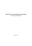
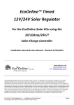
1
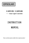
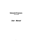
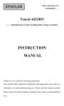
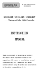
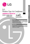
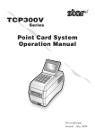
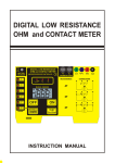
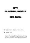
Specification of excellent controller 200W-600 W series User- Manual wind/solar hybrid Controller Model No.: SSWC-06-1224-TA Version: 5.0 Thank you very much for selecting our product! This manual offers important information and suggestions with respect to installation, use and troubleshooting, etc. Please read this manual carefully before using the product and pay attention to the safety recommendations in it Page - 1 - Specification of excellent controller Contents 1. Important Safety Operation Information…………………………..2 2. General Safety Information……………….………….………………..2 3. General Description……………………….……………………….….2 4. Product features……………………..……………………………...3 5. Protection Functions………………..………………………………3 6. Controller application mode illumination……….…………………3 7. Instruction for panel of controller………….………………………3 8. Installation Instructions ………………………………………4 8.1 General Installation Notes ………………………………………4 8.2 Mounting ………………………….……………………………4 8.3 System connection with controller………………………………5 Step 1: Battery Wiring….……………...……………….…....………5 Step 2: Loading Wiring….………………..……………….…...……6 Step 3: Solar Module Wiring…………………….……….…….……7 Step 4: Wind-turbine (PMG) Wiring……………...……... …………7 Step 5: Switch power wiring….………..…….….……………..……8 9. 10. 11. 12. 13. 14. 15. 16. 17. 18. 19. 20. Step 6: Accessories (Option) ………………………………………..8 Step 7: Confirmation for Wiring ……………………..……………..9 Step 8: Power-up sequence ……………………….…………………9 LCD Browsing Instructions ………………………………………….10 LCD display when system abnormal situation ……………………...12 System setting Instructions ………………….………………………13 Controller working mode instruction ………………..……………15 About time-delay illumination …………………...…………………16 Performance Parameters ………………………….…………………17 Model Description …………………………………………………..18 Maintenance ………………….………………………..……………18 Troubleshooting Guide ……….…………………………..…………19 Warranty and after Sales Service …….……………………..………19 Declare……………….. ………………………………..…………20 Dimensions ……………………………………………………….20 Page - 2 - Specification of excellent controller 1. Important Safety Operation Information This manual contains important safety, installation and operating instructions for controller. WARNING: Reverse connection of positive (+) and negative (-) is prohibited ! Short-circuit of positive (+) and negative (-) is prohibited ! DC supply, switching power supply or motor driven generator to simulate the wind generator to charge testing is prohibited! CAUTION: If your battery voltage lower than 9V, connect to controller is prohibited! Controller was damaged much possibly caused by this occurrence. Solar panel and loading rated power do not higher than controller rating accordingly. 2. General Safety Information Please don‘t use low quality battery to avoid leakage, rust or burn. Please don‘t use thin or low quality cable to avoid leakage or fire. Do not open cover and maintain personally. Keep it away from water, moist, rain, severe dust, shaking, corrosion and Intensive or under intense electromagnetic interference. This machine prohibited around the place with any flammable, explosive and dangerous goods. Keep any symbols on the controller complete. To avoid accidents, keep it away from this children. 3. General Description The advanced wind/solar hybrid controller is specially designed for high-end small-scale wind/solar hybrid system and especially suitable for wind/solar hybrid street light system and wind/solar hybrid monitoring system. Topology Diagram Page - 3 - Specification of excellent controller 4. 5. 6. Product features MPPT technology to optimize using the wind energy. (Optional) Boost circuit designed. User can set this voltage parameter. (Optional) 12V/24V System automatic recognition function. (Optional) Be able to use for 200W-600W wind turbine with high compatibility. Digital design,module structure, stable and reliable. Dual-line output, light sensor and timer functions, morning lighting, constantly output 24hours. User can adjust setting of system parameters as voltage protection point, boost voltage, light sensor voltage, timer. and so on. Protection Functions Solar cells reverse charging, solar cells anti-reverse connection. Battery over-charging, over-discharge, battery anti-reverse connection. Over-load, load anti-reverse connection and load short circuit protection Wind turbine current and voltage limited, rotation limited and brake. Controller application mode illumination This device be able to be using several type systems as following: MODE:A street lighting control mode MODE:C monitor system control mode * If your buy is city-electric supply type, as following mode MODE:B street lighting control mode MODE:D monitor system control mode * How to set MODE:A/C/B/D? 7. please refer to 11.7 section guide. Instruction for panel of controller Page - 4 - Specification of excellent controller ①--- Wiring connection with system terminals ②--- LCD with green backlight ③--- ▲(+) setting key to increase value of parameters. ④--- ―Esc‖ key for existing system without save setting. ⑤--- ▼(-) setting key to reduce value of parameters. ⑥--- ―Enter‖ key to process setting condition or save modification of parameters. 8. Installation Instructions 8.1 General Installation Notes Read through the entire installation section first before beginning installation. Be very careful when working with batteries. Wear eye protection. Have fresh water available to wash and clean any contact with battery acid. Uses insulated tools and avoid placing metal objects near the batteries. Explosive battery gasses may be present during charging .Be certain there is sufficient ventilation to release the gasses. Avoid direct sunlight and do not install in locations where water can enter the controller. Loose power connections and /or corroded wires may result in resistive connections that melt wire insulation, burn surrounding materials, or even cause fire. Ensure tight connections and use cable clamps to secure cables and prevent them from swaying in mobile applications. Use with Gel, Sealed or Flooded batteries only. Battery connection may be wired to one battery or a bank of batteries. The following instructions refer to a singular battery, but it is implied that the battery connection can be made to either one battery or a group of batteries in a battery bank. Select the system cables according to 3A/mm²current density. 8.2 Mounting NOTE: When mounting the controller, ensure free air through the controller heat sink fins. There should be at least 150mm of clearance above and below the controller to allow for cooling. If mounted in an enclosure, ventilation is highly recommended. WARNING: Risk of explosion! Never install the controller in a sealed enclose with flooded batteries! Do not install in a confined area where battery gas can accumulate. Page - 5 - Specification of excellent controller Step 1: Choose Mounting Location: Locate the controller on a vertical surface protected from direct sun, high temperature, and water. Step 2: Check for Clearance: Place the controller in the location where it will be mounted. Verify that there is sufficient room to run wires and that there is sufficient room above and below the controller for air flow Step 3: Mark Holes: Use a pencil or pen to mark the four (4) mounting hole locations on the mounting surface. Step 4: Drill Holes: Remove the controller and drill four sizeable holes in the marked locations. Step 5: Secure Controller: Place the controller on the surface and align the mounting holes with the drilled holes in step 4. Secure the controller in place using the mounting screws. 8.3 System connection with controller NOTE A recommended connection sequence has been provided for maximum safety during installation. Figure 8 - 1 Step 1: Battery Wiring WARNING: Risk of explosion or fire! Never short circuit battery positive (+) and negative (-) or cables If your battery voltage lower than 9V, connect to controller is prohibited! Controller was damaged much possibly caused by this occurrence CAUTION: 1. Before connecting the battery, please measure the battery voltage. 2. For 24V system, batteries voltage must be greater than 18V. 3. For 12V system, battery voltage must be greater than 9V. The controller will identify system by detection of this parameter. If the battery voltage is between 16V-17V, the controller is in discriminant blind spot, the controller will not work normally, please be noted. Page - 6 - Specification of excellent controller Figure 8 - 2 Wire an in-line fuse holder no more than 150mm from the battery positive terminal. Confirm the connection are correct. Step 2: Loading Wiring The controller load output can connect DC electronic devices of which rated voltage is same as battery‘s. Device will provide battery voltage to the loads. DC loading could be LED lamp or monitor devices etc. Figure 8 - 3 1. 2. 3. Connect load1 positive (+) and negative (-) to the controller related terminals and connect load2 positive (+) and negative (-) to the controller related terminals accordingly. The load terminals may exist voltage, connect carefully to avoid short circuit. An in-line fuse holder should be wired in series in the load positive (+) or negative (-) wire as shown. Do not insert a fuse at this time. Page - 7 - Specification of excellent controller 4. Confirm the connections are correct. If wiring the load connection to a load distribution panel, each load circuit should be fused separately. The total load draw current should not exceed the 10A load rating. Step 3: Solar Module Wiring WARNING Risk of electric shock! Exercise caution when handling solar wiring. The solar module(s) high voltage output can cause severe shock or injury. Cover the solar module(s) from the sun before installing solar wiring. CAUTION: 1. If you can not confirm the scientific and rational PV module connection by series or parallel way, please contact the manufacturer of controller. 2. The controller can be applied to the single crystal silicon, polycrystalline silicon, thin-film photo voltaic group 3. PV groups open circuit voltage (Voc) do not higher than rated battery bank voltage 2.0times. 4. PV groups operation voltage (Vmp) do not lower than rated battery bank voltage 1.2times. Figure 8 - 4 Step 4: Wind-turbine (PMG) Wiring Figure 8 - 5 Page - 8 - Specification of excellent controller NOTE: The wind-turbine rated voltage (@ rated wind-speed level) should be equal to voltage of battery bank If your wind-turbine output is DC power, +/- polarity wire can connect to 2 of whereby 3 terminals be optional. Please connect wind-turbine to controller related terminals . Step 5: Switch power wiring If your buy unit isn‘t this type mode, please ignore following guide. Please skip to next step 6 Figure 8 - 6 1. There are 2 wires from controller need connect to switch power. Red-wire is positive , Black wire is negative polarity. 2. Please make sure connection are correct with switch power related terminals 3. Switch power AC input terminal please connect with your city-electric. Please refer to instruction from manufacturer of switch power. CAUTION: reverse polarity connection was prohibited! Step 6: Accessories (Option) If your buy unit isn‘t this type mode, please ignore following guide. Please skip to next step 7 1. Install the data-communication wire if required. 2. Refer to the instructions provided for detailed installation procedures of software guide. Page - 9 - Specification of excellent controller Figure 8 - 7 Step 7: Confirmation for Wiring Double-check the wiring in step1 through 5. Confirm correct polarity at each connection. Verify that all 10 power terminals are tightened. Figure 8 - 8 Step 8: Power-up sequence after confirmation of connection 1. Turn-on battery firstly ! 2. Turn-on solar panel 3. Turn-on wind-turbine 4. Turn-on DC loading 5. Turn-on switch power for city-electric (if be this mode) CAUTION if you would take down system as need, must be comply with following sequence. 1. Remove wind-turbine wiring firstly! Page - 10 - Specification of excellent controller 2. 3. 4. Remove solar panel wiring Remove DC load wiring Remove batteries wiring lastly When battery power is applied and the controller powers up, the LCD will showing message as ― system initial, please wait…‖. Meantime, backlight is lighting in green approximate 5 seconds, then backlight would turn-off. System is initial … Please wait… If the controller does not power up or LCD will not lighting, please refer to following section troubleshooting. 1) Double-check battery connection whether be correct and tight. 2) Make sure battery voltage higher than 9V . 3) Controller DC power output have one(1) minute delay. 4) If battery voltage lower than over-discharge point, no DC power output. 5) As street-lighting system, while solar panel voltage higher than threshold voltage, controller no DC power output. 9. LCD Browsing Instructions LCD backlight is on after pressing any key. The backlight will last 15 seconds, then would be power-off if you stop press any key long time. 9.1 Description of Key-Press: ▲(+)key: In browsing window, press this key to back previous page content of LCD showing. ▼(—)key: In browsing window, press this key to look next page content of LCD showing 9.2 Displayed Content Description: 9.2.1 while battery connected with controller and power up, then LCD would showing content as ―system is initial, please wait…..‖ and last approximate 3 seconds with backlight. Page - 11 - Specification of excellent controller System is initial … Please wait… 9.2.2 Then, LCD screen will show 1st page content of screen. Ub : xx.x V Eb : xxx% Ub: voltage of batteries Eb: mean power volume of battery with percent format Press▼(-) key to browse 2nd page content of screen. Uw : Iw : xx.x V xx.x A Uw:meaning voltage of wind-turbine, but this value is DC voltage, which be rectified voltage from wind-turbine output. Iw:charging current from wind-turbine to battery. Press▼(-) key to browse 3rd page content of screen Us : Is : xx.x V xx.x A Us:mean solar panel voltage Is:charging current from solar panel to battery. Press▼(-) key to browse 4th page content of screen Output ON night Output is turn-on, will show ―ON night‖ and if output was turn-off, will show ―OFF day‖ characters Press▼(-) key to browse 5th page content of screen BATTERY normal It will show ―normal‖ while battery voltage is good condition, and will show ―float‖ when floating charge states. If you stop pressing any key for 60 seconds approximately, the LCD would showing back to first browsing page content. Page - 12 - Specification of excellent controller 10. LCD display when system abnormal situation If the battery is overcharge, the LCD display Ub : xx.x V over_v Uplink displays the current battery voltage Downlink display ―over_v‖ characters, which be flashing Tip: Once the battery voltage drops to the overcharge recovery value, the LCD is automatically back to first browsing page content. If the battery voltage is under voltage, the LCD display Ub : xx.x V low_v Uplink displays the current battery Downlink display ―low_v‖ character, which be flashing Tip: Once the battery voltage rise to the discharge recovery value, the LCD is automatically back to first browsing page content. If loading overload, over current, short circuit, the LCD display LOAD over_A The screen display "over_A" characters, and flashing. Please check the loading circuit whether be right Tip: Once the load abnormal is troubleshooting, the screen will automatically back to first browsing page content. If the wind turbines in the brake protection status, the screen display W_T Brake The screen display "Brake" characters, and flashing. This is the normal brake protection action for wind turbine. Tip: Once the wind turbine brake action is stop, the screen will automatically back to first browsing page content. Page - 13 - Specification of excellent controller 11. System setting Instructions “ENTER” key:symbolizes set or confirm: press this key to access setting window. In setting window, press this key to choice each parameter and go to next page. “Esc” key: cancel or manual switch. In setting window, press this key to return to browsing window and do not save the modified parameters. 11.1 Press ―ENTER‖ to access following content of screen firstly. V1 : V2 : xx.xV xx.xV V1:Battery over-discharge voltage V2:Battery over-discharge recovery voltage Press ▲(+) key or ▼(-) key to adjust the value, each press means increase or reduce 0.1V. 11.2 Press V3 : V4 : ―ENTER‖ xx.xV xx.xV key to next page: V3:Battery over-charge voltage V4:Battery over-charge recovery voltage Press ▲(+) key or ▼(-) key to adjust the value, each press means increase or reduce 0.1V. Press ―ENTER‖ to choose. 11.3 Press ‗ENTER‘ key to next page: V5 : xx.xV T1-1 : xxh V5: floating charge voltage T1-1: Line1 whole power output time Press ▲(+) key or ▼(-) key to adjust the number, each press means increase or reduce 0.1V. If set time, each press means increase or reduce 1 hour while setting time. Press ‗ENTER‘ to choose. 11.4 Press ‗ENTER‘ key to next page: T1-2 : xxh T1-3 : xxh T1-2: Line1 half-power output time T1-3: Line1 Turn-off output time Press ▲(+) key or ▼(-) key to adjust the number, each press means increase or reduce 1 hour. Press ―ENTER‖ to choose. Page - 14 - Specification of excellent controller 11.5 Press ―ENTER‖ key to next page: T2-1 : xxh T2-2 : xxh T2-1: T2-2: Line2 whole power output time Line2 half power output time Press ▲(+) key or ▼(-) key to adjust the number, each press means increase or reduce 1 hour. Press ‗ENTER‘ to choose. 11.6 Press ‗ENTER‘ key to next page: T2-3 : xxh VsTH : xxV T2-3: Line2 Turn-off output time VsTH:DC power output turn-on while voltage of solar panel lower than this value, and turn-off while solar panel voltage higher than it Press ▲(+) key or ▼(-) key to adjust the number, each press means increase or reduce 1 hour. If set voltage, each press means increase or reduce 1V . Press ‗ENTER‘ to choose. 11.7 Press ‗ENTER‘ key to next page: VwCH : xxV MODE : X 11.7.1 ―VwTH‖ this value is mean controller would rise voltage of wind turbine to charge battery. Please be mind if your system are 24V, will showing is 12v, it was rectified value, wind-turbine output approximate 10vac. 12v system, will showing6.0v. wind-turbine output approximate 6vac. Press ▲(+) key or ▼(-) key to adjust the number, each press means increase or reduce 1.0V. CAUTION: This parameter must be modify by professional technician, general user re-setting is prohibited! 11.7.2 Mode parameter is meaning different system Press ▲(+) key or ▼(-) key to choose mode type according to actual your system correctly ! Page - 15 - Specification of excellent controller 11.8 Press ―ENTER‖ key to next page: Save ? Y/N If you have selected ‗Y‘ and press ‗Enter‘ key, controller will save value which you modified. If you have selected ‗N‘, controller wouldn‘t save what your adjustment. Saved !!! >>>>>> Then approximate 2seconds later, LCD will back to show first page of browsing window content. CAUTION: When you have completed all setting, please to do disconnection battery aim to power off controller Then 10seconds later, re-start connection of battery to power up controller. This is intent to make sure the program running in you done modified setting condition. PLEASE MAKE SURE NO CONNECTIION WITH WIND-TURBINE AND SOLAR PANEL BEFORE SETTING! 11.9 wind-turbine brake function This advanced controller have manual operation for wind-turbine brake while you have maintenance or repair wind-turbine. Please Press constantly ▲(+) key and ▼(-) key with simultaneity. Then your wind-turbine would slow running gradually to stop. If you stop press keys then brake will be abated. 12. Controller working mode instruction 12.1 Mode A - Street lighting system 1th and 2nd line output are: full power + half power + turn off + morning lighting Page - 16 - Specification of excellent controller NOTE: 1. When solar module voltage goes below the point of NTTV (Night Time Threshold Voltage) at sunset, the solar controller will recognize the starting voltage and turn on the load after 1 minutes delay. 2. When solar module voltage goes above point of DTTV (Day Time Threshold Voltage), the solar controller will recognize the starting voltage and turn off the load after 1 minutes delay. 3. We set NTTV equal to DTTV, by ‗VsTH‘ this parameter to adjust. T1-X mean 1th line output, T2-X mean 2nd line output(for example T1-X) T1-1 :default is 5 , mean full-power time is 5hours,then go intoT1-2 step. T1-2 :default is 0 , mean half- power time is 0hours,then go intoT1-3 step directly. T1-3 :default value be 5 , mean turn off time is 5hours,then go intoT1-4 step. T1-4 :this process is balance of whole night time. And turn off lamp while dawn. This value would not show on LCD, so this value is not adjustable. Of course , you could to cover this process by -2,-3 value with longer time. 12.2 DC output constant (MODE:C) Such so mode control way is for monitor system .On this mode, related street lighting function will be shut-down. DC power will be output constant with 24hours. 13. About time-delay illumination Delay items Duration Power up DC output (lighting) 60 seconds approximately Dusk to light lamp (NTTV) for output 60 seconds approximately Dawn to turn-off lamp (DTTV) for output 60 seconds approximately Over-charge protection on charge 10 seconds approximately Over-charge recovery on charge 15 minutes approximately Over-discharge cut-off output 10 seconds approximately Over-discharge recovery for output 2 minutes approximately Loading abnormally output DC power 2 minutes approximately Wind-turbine brake 1 hours approximately Page - 17 - Specification of excellent controller 14. Performance Parameters 14.1 Wind generator control set-up definition: Rated Wind Turbine Power 200W – 600W Wind Turbine brake voltage (12v/24v) 15VAC / 25VAC Wind Turbine brake current (12v/24v) 10A / 20A 14.2 Solar panel set-up definition PV max power (12v/24v) 150W / 300W PV max open circuit voltage (12v/24v) 24.0V / 48.0V PV max charge current 12.5A 14.3 Battery management definition Over-discharge Voltage (12V/24V) 10.5V / 20.0V adjustable Over-discharge Recovery Voltage (12V/24V) 12.0V / 24.0V adjustable Over-charge Voltage(12V/24V) 15.0V / 30.0V adjustable Over-charge Recovery Voltage(12V/24V) 13.5V / 27.0V adjustable 14.4 Output Set-up function: Each Line Output Current rating 5A Each Line Output rated Power (12V/24V) 60W / 120W Dusk and dawn threshold voltage default : 6.0V ( VsTH) adjustable 14.5 Product Conventional parameter Display LCD with backlight Self-consumption ≦30mA (backlight turn-off) Temperature-compensation coefficient -35mV/℃ Ambient temp. range -30℃ to +55℃ Store temp. range -35℃ to +80℃ Humidity range 10% - 90% Altitude work ≤5000 meters above sea level Protection class IP55 Data-communication RS232 / RS485/USB be optional Page - 18 - (25℃ ref.) (NC) Specification of excellent controller 15. Model Description 16. Maintenance The following inspections and maintenance tasks are recommended at least two times per year for best controller performance. Check that the controller is securely mounted in a clean and dry environment. Check that the air flow and ventilation around the controller is not blocked. Clear all dirt or fragments on the heat sink. Check all the naked wires to make sure insulation is not damaged for serious polarization, frictional wear, dryness, insects or rats etc. Maintain or replace the wires if necessary. Tighten all the terminals. Inspect for loose, broken, or burnt wire connections. Check and confirm that LCD is consistent with required. Pay attention to any troubleshooting or error indication. Take necessary corrective action. Confirm that all the system components are ground connected tightly and correctly. Confirm that all the terminals have no corrosion, insulation damaged, high temperature or burnt/discolored sign, tighten terminal screws to the suggested torque. Inspect for dirt, insects and corrosion, and clear up. Check and confirm that lighting arrester is in good condition. Replace a new one in time to avoid damaging of the controller and even other equipments. Warning Risk of electric shock! Make sure all the power is turned off before above operations, and then follow the corresponding inspections and operations. Page - 19 - Specification of excellent controller 17. Troubleshooting Guide: Fault Phenomenon Connected to the 1 battery, the controller does not work Reason The battery voltage is too low The battery voltage is below the release point Connected to the 2 battery, the controller does not output 3 The controller is not charging Still no output when 4 Batteries rose to a recovery point ,from over-discharge point 5 The speed of the wind turbine is very low 18. Access photovoltaic panels, switch on PV Controller is 1 minute output delay (battery voltage is normal) The voltage of Wind turbine and photovoltaic panels too low The battery voltage is too high, has been in the overvoltage condition Solution Charger to charge the battery or replace the battery Normal, wait for the system to charge to the recovery point Remove the photovoltaic panels Normal Observe When Wind or PV is strong enough Normal The controller has two minutes, delayed output observe and test after 1 minute The wind speed is too low Observe When wind speed is high The battery is not connected, the controller starts the open-circuit protection function The battery voltage is too high, has been in the brake condition Securely connected again Observe after the Battery discharge Warranty and after Sales Service The charge controller is warranted to be free from defects for a period of ONE (1) years from the date of shipment to the original end user. We will, at its option, repair or replace any such defective products. Claim procedure: Before requesting warranty service, check the Operation Manual to be certain that there is a problem with the controller. Return the defective product to us with shipping charges prepaid if problem cannot be solved. Provide proof of date and place of purchase. To obtain rapid service under this warranty, the Page - 20 - Specification of excellent controller returned products must include the model, serial number and detailed reason for the failure, the module type and size, type of batteries and system loads. This information is critical to a rapid disposition of your warranty claim. This warranty does not apply under the following conditions: 1. Damage by accident, negligence ,abuse or improper use. 2. PV or load current exceeding the rating of product. 3. Unauthorized product modification attempted repair. 4. Damage occurring during shipment. 5. Damage results from acts of nature such as lightning, weather extremes. 6. Irreclaimable mechanical damage. 19. Declare: The product has applied for patent protection, counterfeiting will be subject to legal sanctions. Our Company reserves the right to change products and without notice when products update. 20. Dimensions (mm) Net weight: 1.2KG Page - 21 -