1
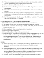
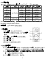
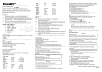
MT-5110 3 1/2 Capacitance Meter User’s Manual 1. FEATURES Easy and correct readout. High measuring accuracy. Measurements are possible even under a strong magnetic field. LSI-circuit provides high reliability and durability. Input overload protection is provided. LCD display for low power consumption and clear readout even in bright ambient light conditions. Light-weight and compact construction for easy operation. Low battery condition is indicated on the LCD display. 2. SPECIFICATIONS 2-1.GENERAL SPECIFICATIONS Display: LCD (Liquid Crystal Display) Max. Indication 1999. Measurement: C (Capacitance) Range: single 9 position, whole range value (from 0.1pF to 20000uF) Zero Adjustment :Manual (range: 20pF) Calibrate Adjustment: Have two internal adjustments. One is panel Zero adjustment. Over-input :Display shows 1 . Backlight Function: it went out by itself within 8 seconds. Sampling Time: 0~5second Operating Temp :0 to 40 Operating Humidity: 80% MAX.R.H. Power Supply : Single, standard 9 volt battery. NEDA 1604IEC6F22 Typical consumption current: 3~4mA (RANGE: 200pF-200uF) Standard Accessories: Test alligator clips (red & black)…1 pair. Instruction manual………… ……..1 pc. 2 2-2. ELECTRICAL SPECIFICATION Accuracy is (percentage of reading + number of digit) at 23 Range 200pF Accuracy (0.5%+7) 5 ,<80%RH. Resolution Test Frequency Max indication value 0.1pF 800Hz 199.9pF 2nF 1pF 800Hz 1.999nF 20nF 10pF 800Hz 19.99nF 200nF 100pF 800Hz 199.9nF (0.5%+5) 2uF 1000pF 800Hz 1.999uF 20uF 0.01uF 80Hz 19.99uF 200uF 0.1uF 8Hz 199.9uF 2000uF 1uF 8Hz 1999uF (2%+5) 20000uF 10uF 8Hz (3%+10) 1999( 10)uF pF= Pico Farad(10 -12F ) nF= nan Farad(10 -9F). uF= micro Farad(10-6F) Excitative voltage: Max.2.8Vrms Overload Rating: Protection by a 0.1A/36V fuse. 3. OPERATION PANEL 1. LCD display: display the test value and unit. 2. Backlight key: press the button lightly; it was turning off by itself about 8 seconds. 3. Function Selector: It is used for power on and changes the range of function. 4. Capacitance″ ″input terminal. 5. Capacitance ″+″input terminal. 6. Zero knob: Knob to zero when test low capacitance 4. CONSIDERATION OF MEASUREMENT (1) This C METER is intended for measuring the capacitance value of a capacitor. It is not intended for determining the “Q” f actor for above reactive components. Misleading readings may be obtained if the measurement of capacitance of a resistor is attempted. 3 (2) (3) (4) (5) (6) (7) When measuring components within circuit that circuit must be switched off and de-energized before connecting the test leads. Do not close (black & red) test leads. Instruments used in dusty environments should be stripped and cleaned periodically. Do not leave the instrument exposed to direct heat from the sun for long periods. Before removing the battery and fuse compartment cover, ensure that the instrument is disconnected with any circuit and the power switch is in the off position. For all measurements, should connect BLACK test lead into “ -” terminal and RED test lead into “+” terminal. 5. CAPACITANCE(C) MEASURING PROCEDURE (1) Select the range selector for the maximum expected capacitance. (2) The power will on when the selector switch away from OFF position. (3) Check "0" indication: If test range is 200pF, 2nF, 20nF, should check "0" indication before test. (4) Observe polarity when connecting polarized capacitors. (5) Full discharge any capacitors. (6) Connect the alligator clips to the capacitors leads. (7) Read the display. The value is direct reading in the electrical unit (pF, nF, uF) indicated at the selected range switch. If display show “1”, It indicate on Out-of-Range measurement. If the display indicates one or more leading zeros, shift to the next lower range scale to improve the resolution of the measurement. NOTE: (a) If the capacitance value is unmarked, start with the 200pF range and keep increasing until the over-range indication goes off and a reading is obtained. (b) A shorted capacitor will read over-range on all ranges. A capacitance with low voltage leakage will read over range, or a much higher value than normal. An open capacitor will read zero on all ranges (possibly a few pF on 200pF range, due to stray capacitance of the instrument). (c) Measure of very low capacitance should be performed using extremely 4 short leads in order to avoid introducing any stray inductance. (d) When using the optioned test leads, remember that the leads introduce a measurable capacitance to the measurement. As a first approximation, the test lead capacitance may be measured by opening the leads at the trips, recording the open circuit value and subtracting that value. (e) Capacitors, especially electrolytic, often have notoriously wide tolerances. Do not be surprised if the measured value is greater than the value marked on the capacitor, unless it is a close tolerance type.However, values are seldom drastically below the rated value. (f) If changing range, measured value will be changed; leakage-voltage capacitors will be checked also. Leakage-resistance will be decreased in lower range. 6. MAINTENANCE 1) 9-Volt battery replacement a. Ensure the instrument is not connected to any external circuit. Set the selector switch to OFF position and remove the test leads from terminals. b. Remove the screw on the bottom case and lift the bottom case. c. Remove the spent battery and replace it with a battery of the same type. 2) Fuse replacement a. Ensure the instrument is not connected to any external circuit. Set the selector switch to OFF position and remove the test leads from terminals. b. Remove the screw on the bottom case and lift the bottom case. c. Replace the fuse with the same type and rating: 5 20mm, 200mA/250V, fast-blow fuse or as the replacements. The specifications are subject to change without notice. The content of this manual is regarded as correct, error or omits Pls. contact with factory. We hereby will not be responsible for the accident and damage caused by improper operation. The function stated for this User Manual cannot be the reason of special usage. 5 MT-5110 3 1/2 數位電容錶 1. 色 依然可以測量 LSI LCD LCD 顯示 小型機構設計 會顯 壓 即使 室內 2. 2-1.一般 顯示 LCD( 螢幕) 最大讀值 1999 C( ) 9 , 0.1pF to 20000uF 歸 動( ±20pF) 含2個 裝置。其中 1 個是歸 0 輸入超過 螢幕 “1” 背光 8 採 0 ~5second 0 ℃ ~40 ℃ .最大濕度:80%.R.H. 1個 9 NEDA 1604IEC 6F 22 標準 3〜4 200pF - 200uF 配 魚 ( )1 對 操作說明書 1 本 6 下 2-2. 電氣規格 ± +個 數 23 ± 5℃ <80 範圍 精準度 分辨率 測試頻率 最大顯示值 ±(0.5%+7) 200pF 0.1pF 800Hz 199.9pF 2nF 1pF 800Hz 1.999nF 20nF 10pF 800Hz 19.99nF 200nF 100pF 800Hz 199.9nF ±(0.5%+5) 2uF 1000pF 800Hz 1.999uF 20uF 0.01uF 80Hz 19.99uF 200uF 0.1uF 8Hz 199.9uF 2000uF ±(2%+5) 1uF 8Hz 1999uF 20000uF ±(3%+10) 10uF 8Hz 1999(×10)uF pF= Pico Farad(10-12F ) nF= nan Farad(10 -9F). uF= micro Farad(10 -6F) Excitative voltage: Max.2.8Vrms 功率超載: 0.1A/36V 3. 操作面板 1.LCD 螢幕 2.背光按鍵 3. 4. 5. 6. 4. 8 後自動 旋鈕 啟動及 輸入端 ″ ″ 輸入端 ″+ ″ : 注意事項 台電容測試器用 值 “Q” 零件的 值 (2) 測量零件內部迴路前,必須確認這個迴路必須在沒有通電的狀態 下 (3) 關閉 (1) 7 (4) (5) (6) (7) 5. (1) (2) (3) (4) (5) (6) (7) (a) (b) (c) (d) (e) (f) 把 暴露在 打開 下 子 確認 “ - ” 紅色 線+” C 步驟 將功能旋鈕轉到待測試 預期 大值 同步開啟 “0” 200pF 2nF 20nF 測試前 “0” 表示 測試有極性 檢查其 執行 放電 魚 取螢幕顯示的數值,電容值 (pF, nF, uF) 取, 螢 幕 “1” 示測量結果超過選定測量範圍 螢幕 在數字前面 切換到 檔位 不知道待測物品 200pF 持續 超量指示熄滅及讀取到讀值 測量時會顯示超過量測範圍的讀值 的電容 漏電 讀值將會較高或超過範圍 pF 200pF 引起 訊 的 測 試 當使用任選的測試表筆時, 記住表筆可能引入一個的電容. 首先, 測試表筆應在打開筆尖的情況下, 測出該表筆的電容, 記錄其開路 值並從測試結果中減去此值 電容 有 的 上的 ,不管如何 8 測量值 (g) 6. 1) 9 更 a. 確認 OFF 試 b. 取下底蓋的螺絲與蓋子 c. 取出電池並更換一個同類型的電池 2) 更 a.確認 OFF 測試 b.取下底蓋的螺絲與蓋子 c. 的 替換 5×20mm, 200mA/250V 測 本說明書如有改變,恕不另行通知 本說明書的內容被認為是正確的,若用戶發現有錯誤、遺漏等,請與生產廠 家聯繫。 本公司不承擔由於用戶錯誤操作所引起的事故和危害 。 本說明書所講述的功能,不作為將產品用做特殊用途的理由。 9 ©2011 Prokit’s Industries Co., LTD. All rights reserved 2011001(T) 10