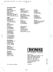
1
MT-1630 User Manual
■2V ~
■20V ~
■200V~
■600 ~
0.001V
0.01V
0.1V
1V
±(1.0%+3d)
±(1.0%+3d)
±(1.0%+3d)
±(1.2%+3d)
1. SAFETY INFORMATION
Warning
Using this instrument should special attention to improper use may cause
electric shock or damage, in use should follow the usual safety rules and in full
compliance with the security measures provided for manual. In order to take full
advantage of instrument function and ensure the safe operation, please read these
instructions and follow them strictly
1.1 Preparation
1.1.1 Using the instrument the user must comply with standards of safety rules
--Electric shock protection --to avoid the misuse of instruments
1.1.2 When you received the instrument, check whether the damage in transit
1.1.3 Test lead and test probe must be in good condition connect the test lead before you
connect the test probe, when you disconnect them ,disconnect the test probe
first
1.1.4 When servicing the meter use only specified replacement parts
1.1.5 Inspect the test lead for damaged insulation or exposed metal, check the test lead
and test probe for continuity. Replace damaged test lead before you use meter
2. FRONT PANEL DESRIPTION
(1)
“LIGHT” button
(2)
“SELECT” button
(3)
Display 3 1/2 digits LCD
with max reading 1999
(4)
“HOLD” button
(5)
Function switch
(6)
Scalable probe block
(7)
Test probe
(8)
Test lead
3. SPECIFICATIONS
Accuracy is specified for a period of one year after calibration and at 23±5℃ with relative
humidity up to 75%
3.1 Review
Auto-Ranging
The max voltage the meter can measure is 600V DC or AC between COM and Earth
Ground
Working height: Max 2000m
Display: 3 1/2 –digit LCD
Max reading of 1999
Polarity: Auto polarity indication “-”expressed as negative polarity
Over range indication: ”OL” on display
Sampling Rate: Approximate 3 times per sec
Functional power unit display
Low battery indication “
” on LCD
Fuse protection: mA: Resettable Fuse
Auto shutdown: 15minutes
Battery: 1.5V2LR44
Operation Temperature 0℃-40℃<80%RH
Storage temperature: -10℃-50℃<70%RH Remove the battery
Dimensions: 205mm×35mm×30mm
Weight: about 96g (without battery)
AC/DC Current
Range
■20mA
■200mA
■20mA ~
■200mA ~
AC/DC Voltage
Range
■200m V
■2 V
■20 V
■200 V
■600 V
Resolution
0.01mA
0.01mA
0.01mA
0.01mA
Resolution
0.1mV
0.001V
0.01V
0.1V
1V
Accuracy
±(1.5%+10d)
±(1.5%+10d)
±(3.0%+10d)
±(3.0%+10d)
Accuracy
±(0.8%+5d)
±(0.8%+5d)
±(0.8%+5d)
±(0.8%+5d)
±(0.8%+5d)
Resistance
Range
■200Ω
■2KΩ
■20KΩ
■200 KΩ
■2MΩ
■20M Ω
Resolution
0.1Ω
1Ω
0.01KΩ
0.1KΩ
1KΩ
0.01MΩ
Accuracy
±(1.0%+5d)
±(1.0%+3d)
±(1.0%+3d)
±(1.0%+3d)
±(1.0%+3d)
±(1.2%+5d)
Continuity Test
Diode test
3.2 Use
3.2.1 Use the proper function and range for your measurements
3.2.2 When serving the meter, use the same model number or identical electrical
specification replacement parts
3.2.3 When using the probe s keep your fingers behind the finger guards on the unit
3.2.4 Do not input higher than 600V between the two meter’s input terminal to avoid
electric shock and damage to the meter
3.2.5 When the meter working at an effective voltage over 60V DC or 30V AC
(RMS),special care should be taken for there is danger of electric shock
3.2.6 Disconnect circuit power and discharge all high-voltage capacitors before testing
resistance, continuity and diode
3.2.7 Do not testing resistance, continuity and diode with electricity
3.2.8 Before pushing the function switch to charge functions disconnect test lead and
test probe from the circuit under test
3.2.9 Do not operate the meter around explosive gas .vapor or dust
3.2.10 Do not use the meter if it operates abnormally ,Protection may be impaired, when
in doubt have the meter serviced
3.2.11 Do not use the meter with the battery door or portions of the cover removed or
loosened
3.2.12 Do not store the meter in direct sunlight, high temperature and high humidity
4. OPERATION INSTRUCTION
4.1 Reading hold
After pressing “HOLD” button,the present reading will be held on the display ,to exit
from the mode ,just press button again
4.2 "SELECT" Button
This button is used for the function's change between: VDC/AC,
resistance/diode/continuity..
4.3 Auto Power-off
If the instrument is not used or stays in a range position for more than 15
minutes, the power supply will be switched off and the instrument will be in
sleep status. To arouse the instrument from sleep, turn the function switch or press the
"HOLD" button.
4.4 Measuring Voltage
4.4.1 Put away the test probe protective cover, and takes test lead from the
back box.
4.4.2 Set the function switch in V position
4.4.3 Press the "SELECT" button to set the unit in DC or AC range.
4.4.4 Connect the test probe and test lead across the source or load to be
measured.
4.4.5 The display will show the reading along with the polarity of the test probe.
Warning
Risk of electric shock.
The max. permitted input voltage: 600V
4.5 Measuring Resistance
Warning
Risk of electric shock.
When measuring resistance, be sure disconnect circuit.
4.5.1 Put away the test probe protective cover.
4.5.2 Take test lead from the back box.
4.5.3 Set the function switch in the
position.
4.5.4 Connect the test lead and test probe across the resistance to be measured.
4.5.5 Read the value on LCD.
Note: - If the resistance is 2 1M, it takes several seconds to stabilize. It is normal.
- If the input terminal is in open circuit, overload mark will be displayed on LCD.
- Before measuring resistance, make sure that the power supply has been
switched off and all the capacitors have been discharged..
4.6 Measuring Diode
4.6.1 Put away the test probe protective cover.
4.6.2 Take test lead from the back box.
4.6.3 Set the function switch to
position.
4.6.4 Press "SELECT button to make the display show ~
4.6.5 Connect the test probe and test lead across the diode (test probe to the
positive pole of the diode, test lead to negative pole).
4.6.6 Read the forward voltage on LCD.
Note:
- Meter shows an approximation of diode forward voltage drop
- If the instrument and test lead reverse connection, the LCD will show "OL".
- If the instrument and test lead open circuit, the LCD will show "OL".
4.7 Audible Continuity
4.7.1 Put away the test probe protective cover.
4.7.2 Take test lead from the back box.
' Ω’ position.
4.7.3 Set the function switch to '
4.7.4 Press "SELECT button to make the display show “
”
4.7.5 Connect the test lead and test probe across the resistance to be
measured.
4.7.6 The buzzer sounds if the resistance of a circuit under test is less than
50Ω; it may or may not sounds if the resistance of a circuit under test is
between 50Ω to 120Ω; it does not sound if the resistance of a circuit
under test is higher than 120.
Note:
- If the test lead reverse connection or the resistance is higher than 200Ω, the LCD will
show "OL".
4.8 Current measurement
Warning
Risk of electric shock.
When current measurement has been completed, disconnect the connection
between the conductor under test and the jaw, and remove the conductor away
from the transformer jaw of the Meter.
4.8.1 Put away the test probe protective cover. And take test lead from the back box.
4.8.2 Set the function switch in mA position
4.8.3 Press the "SELECT button to set the unit in DC or AC range.
4.8.4 Connect the test probe and test lead across the source or load to be measured.
4.8.5 The display will show the reading along with the polarity of the test probe.
5. MAINTENANCE
Warning
Do not attempt to repair or service your Meter unless you are qualified
to do so and have the relevant calibration, performance test, and service
information.
5.1.1 Periodically wipe the case with a damp cloth and mild detergent. Do not use
abrasive or solvents.
5.1.2 To clean the terminals with cotton bar with detergent, as dirt or moisture
in the terminals can affect readings.
5.1.3 To avoid electrical shock or damage to the Meter, do not get water inside
the case.
5.1.4 Turn the meter power off when it is not in use.
5.1.5 Take out the battery when it is not using for a long time.
5.16 Do not use or store the Meter in a place of humidity, high temperature,
explosive, inflammable and strong magnetic field.
5.2 Battery Replacement
5.2.1 Replace the battery as soon as the battery indicator“
”appears.
5.2.2 Remove the screw from the battery compartment, and separate the
battery compartment from the case bottom.
5.2.3 Take out the old battery and replace with a new battery.
5.2.4 Rejoin the case bottom and the battery compartment, and reinstall the
screw.
©2010 Copy Right by Prokit’s Industries Co., Ltd.
2010001C
MT-1630 使用說明書
1.安全資訊
警告
使用此儀錶應特別注意,不當的使用可能造成電擊或毀壞儀錶,在使
用中應遵循通常的安全規程及完全尊守使用手冊所規定的安全措施。
為了充分地利用儀錶的功能和確保安全操作,請仔細地遵循本節(章)
的用法
此儀錶符合 GB/T13978-82 數位多用表通用技術條件,符合 GB4793.1-1995
(IEC-61010-1:2001)電子測量儀器安全要求,屬二級污染,過壓標準為
CATIII300V
請遵循安全操作指南,保證安全使用儀錶
適當的使用和保護,此儀錶將帶給你令人滿意的服務
1.1 準備
1.1.1 使用儀錶時,用戶必須遵守標準的安全規則:
-通用的防電擊保護
-防止誤用電錶
1.1.2 接收儀錶後,檢查是否在運輸中損壞。
1.1.3 在粗劣的條件下保存,裝運後,檢查並確認儀錶是否損壞
1.1.4 表筆或測試夾必須處於好的狀態,在使用之前,檢查表筆測試夾的絕
緣是否損壞,導線的金屬絲是否裸露。
1.1.5 使用隨表提供的表筆能保證安全,如果需要,必須用同樣或相同等級
的表筆代替
2. 部件名稱
(1)
(2)
(3)
(4)
(5)
(6)
(7)
(8)
3. 規格
LIGHT: LED 照明燈控制按鈕
SELECT 按鈕
LCD 顯示器
HOLD 按鈕
轉換按鈕
可伸縮探針
測試探針
電錶筆
儀錶應以一年為週期,在 18℃-28℃,相對濕度小於 75%的條件下重新校準:
3.1 綜述
3.1.1 自動量程
3.1.2 測量端與大地之間允許的最大電壓:600V DC 或 AC
3.1.3 工作高度:最大 2000m
3.1.4 顯示:LCD 顯示,字高 10mm
3.1.5 最大顯示值:1999(即三位字)
3.1.6 極性指示:自動指示,:“-”表示負極性
3.1.7 超量程顯示:“OL”
3.1.8 採樣時間:約 0.4 秒/次
3.1.9 單位顯示:具有功能,電量單位顯示
3.1.10 電池欠壓指示:LCD顯示
符號
3.1.11 保險絲保護:mA 檔,自複保險絲
3.1.12 自動關機時間:15 分鐘
3.1.13 工作電源:1.5V×2LR44 電池
3.1.14 工作溫度:0℃-40℃<80%RH,<10℃不考慮
3.1.15 儲存溫度:-10℃-50℃<70%RH,取掉電池
3.1.16 尺寸:205mm×35mm×30mm
3.1.17 重量:約 96g(不包括電池)
AC/DC 電流
分辨率
精準度
量程範圍
0.01mA
±(1.5%+10d)
■20mA
■200mA
0.01mA
±(1.5%+10d)
■20mA ~
0.01mA
±(3.0%+10d)
■200mA ~
0.01mA
±(3.0%+10d)
AC/DC 電壓
量程範圍
分辨率
精準度
■200m V
0.1mV
±(0.8%+5d)
■2 V
0.001V
±(0.8%+5d)
■20 V
0.01V
±(0.8%+5d)
■200 V
■600 V
■2V ~
■20V ~
■200V~
■600 ~
電阻
量程範圍
■200Ω
■2KΩ
■20KΩ
■200 KΩ
■2MΩ
■20M Ω
0.1V
1V
0.001V
0.01V
0.1V
1V
分辨率
0.1Ω
1Ω
0.01KΩ
0.1KΩ
1KΩ
0.01MΩ
±(0.8%+5d)
±(0.8%+5d)
±(1.0%+3d)
±(1.0%+3d)
±(1.0%+3d)
±(1.2%+3d)
精準度
±(1.0%+5d)
±(1.0%+3d)
±(1.0%+3d)
±(1.0%+3d)
±(1.0%+3d)
±(1.2%+5d)
連續測試
二極體測試
3.2 使用
3.2.1 使用時,必須用正確的功能及量程
3.2.2 不要超過各量程的保護範圍指示值進行測量
3.2.3 在連接測量電路的時候,不要接觸儀錶和表筆探針的頂端
3.2.4 若測量端與地之間的電壓超過 600V的時,不要測量電壓
3.2.5 在測量時,若被測電壓高於60VDC 或30VAC(有效值
應注意保持手指頭始終在儀錶和表筆的護指裝置之後
3.2.6 在電阻,二極體測試,及線路通斷測試量程不要將儀錶連接電壓源
3.2.7 不要帶電測量電阻,線路通斷,二極體等
3.2.8 在旋轉轉換開關改變測量功能之前,應將儀錶和表筆的探針從被測電路
移開
3.2.9 不要在爆炸性的氣體,蒸汽或灰塵附近使用本儀錶
3.2.10 如果注意到儀錶有任何異常或故障,應停止使用
3.2.11 除非儀錶低殼及電池蓋在原位完全扣緊,否則不應使用儀錶
3.2.12 不要在陽關直射,高溫,高潮濕的情況下儲存或使用儀錶
4.操作介紹
4.1 讀數保持
在測量的過程中,如需耍保持讀數,可按下“HOLD”按鈕,顯示器的
顯示值將被鎖住.再接動‘HOLD‘摟扭,可解除讀數保持狀態.
4.2 功能切換
在電壓電流量程時,按下“SELECT”按鈕,儀錶將在交、直流間切換.在
電阻.二極體及線路通斷量程,按下“SELECT” ,儀錶將在它們間切換.
4.3 自動關機
若在開機後的任何一個 15 分鐘內無任何操作,儀錶將發出五短聲,
一分鐘後發出一長聲並自動關機.自動關機後,若撥動轉換開關或按動
“SELECT”,“LIGHT”-中任何一個按鈕,儀錶恢復工作狀態.
此時若按動 “HOLD” 按鈕,儀錶恢復工作的同時取消自動關機功能.
若按住“HOLD”鍵開機,則取消自動關機功能.
4.4 電壓測量
4.4.1 收起探針保護套,使探針完全露出.
4.4.2 從儀錶背面盒內取出電錶筆.
4-4.3 轉換開關置幹 V;檔位置(置於該檔時.儀錶自動進入直流電壓測
量模式:若要測量交流電壓,可按動 “SELECT” 接鈕切換到交流
測量模式).
4.4.4 將儀錶探針和黑色表筆並接在電壓源或負載兩端進行測量.
4.4.5 在 LCD 上讀數.(測量直流時,顯示器將顯示儀錶探針所接端的極性)
警告
觸電危險,當測量時要格外注意避免觸電.
不要輸入高於 DC600V AC600V 有效值的電壓,顯示更高的電壓值是有可
能的,但有損壞儀錶內部線路或電擊的危險.
注意:在小電壓量程時,表筆未接到被測電路,儀錶會有跳動的讀數,這是正
常的,這是因為儀錶高靈敏度造成的,當把儀錶接到被測被測電路時,就會得
到真實的測量值.
4.5 測量電阻
警告
觸電危險.
在測量線路上的阻抗時,應確定電路電源斷開,電路上的電容器完全放電.
4.5.1 收起探針保護套,使探針完全露出。
4.5.2 從儀錶背面盒內取出黑色表筆.
4.5.3 量程開關置於 量程位置.(置於該檔時儀錶自動進入電阻測量功能)
4.5.4 將儀錶探針和黑色表筆接在被測電阻或線路兩端進行測量.
4.5.5 在 LCD 讀數,
注意:如被測電阻高於 1MΩ.儀錶可能需要幾秒才話穩定讀數,對於高阻值
讀數這是正常的.當輸入開路時,LCD 將顯示“OL”超量程狀態.
4.6 二極管測試
4.6.1 收起探針保護套,使探針完全露出。
4.6.2 從儀錶背面盒內取出黑表筆.
4.6.3 量程開關置於 量程位置.
4.6.4 按動“SELECT”按鈕切換到 測試狀態.
4.6.5 將儀錶探針連接二極體陽極,黑色表筆連接二極體陰極進行測試.
4.6.6 在 LCD 上讀數.
注意:
一儀錶顯示的是二極管正向壓降的近似值.
一如果儀錶和表筆反向連接,則 LCD 顯示“OL”.
一若儀錶和表筆開路,刷 LCD 顯示“OL“
4.7 線路通斷測試
警告
觸電危險,
在測試電路的通斷時,應確定電路電源斷開,電路上的電容器完全放電
4.7.1 收起探針保護套,使探針完全露出.
4.7.2 從儀錶背面盒內取出黑表筆.
4.7.3 量程開關置於 量程位置.
4.7.4 按動"SELECT 一按鈕切換到 線路通斷測試狀態.
4.7.5 將儀錶探針和黑色表筆接在被測線路兩瑞進行測量.
4.7.6 如果被測線路的電阻約小於 50Ω 時,蜂鳴器將發聲;在 50Ω 到
120Ω 時蜂嗚器可能響或不響:大於 120Ω 時蜂鳴器不響,
注意:一如果表筆開路或被測線路電阻大於 200Ω.劇顯示器顯示“OL”
4.8 電流測試
警告
觸電危險.
當開路電壓或對地之同的電壓超過 250V 時,切勿嘗試在電路上進行電流
測量.如果測量時保險管被燒斷,您可能會損壞儀錶或傷害到您自己。
4.8.1 收起探針保護套,使探針完全露出。
4.8.2 從儀錶背面盒內取出黑表筆.
4.8.3 轉換開關置於 mA 位置.(置於該檔時儀錶自動進入直流電流
測量模式:若要測量交流電流.可按動“SELECT’按啦切換到交流
測量模式).
4.8.4 將儀錶探針和黑色表筆串接在待測電路裏.
4.8.5 在 LCD 上讀數.(測量直流時,顯示器將顯示儀錶探針所接端的極性)
5.保養
警告
在打開儀錶的電池蓋之前,應將儀錶和表筆的探針從測量電路移開,以
避免電擊危險
5.l.1 請不要試圖打開底殼調整或修理儀錶,這樣的行動只能由完全瞭解儀錶
及電擊危險的技師執行.
5.1.2 在打開電池蓋或底殼之前,應將儀錶和表筆的探針從被測線路移開.
5.1.3 為避免錯誤的讀數可能引起的電擊,當儀錶顯示 符號時,應更
換電池.
5.1.4 使用濕布和溫和洗滌制清潔儀錶,不要使用研磨劑或溶劑.
5.1.5 儀錶不使用時應將電源關掉,轉換開關旋至 OFF 位置.
5.1.6 如果儀錶長時間不使用,應將電池取出,以防損壞儀錶.
5.2 更換電池
”符號出現,它表明應該更換電池.
5.2.1 如果“
5.2.2 旋開電池蓋的緊固螺釘並將電池蓋移開.
5.2.3 將舊電池更換.
5.2.4 將電池蓋按原樣裝上.
©2010 寶工實業版權所有,翻印必究 2010001C