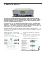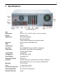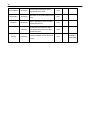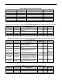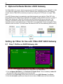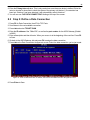
1
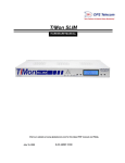
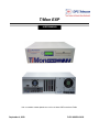
T/Mon EXP
USER MANUAL
Visit our website at www.dpstelecom.com for the latest PDF manual and FAQs.
September 4, 2009
D-OC-UM099.04100
Revision History
September 4, 2009
Added section on Site Dialer functionality. (D-OC-UM099.04100)
August 20, 2009
Added section on SQL Agent. (D-OC-UM098.20100)
July 16, 2009
Revisions to Specs (D-OC-UM097.16100)
May 12, 2009
Image updates, additions to "Initial Setup" section.
(D-OC-UM095.12100)
May 1, 2009
Revisions made to "Setting Up T/Mon for Use with T/Mon EXP
ASCII Gateway" section (D-OC-UM095.01200)
March 18, 2009
Initial release of T/Mon EXP User Manual (D-OC-UM093.18100)
This document contains proprietary information which is protected by copyright. All rights are reserved. No part of this
document may be photocopied without prior written consent of DPS Telecom.
All software and manuals are copyrighted by DPS Telecom. Said software and manuals may not be reproduced, copied,
transmitted or used to make a derivative work, by either mechanical, electronic or any other means in whole or in part, without
prior written consent from DPS Telecom, except as required by United States copyright laws.
© 2009 DPS Telecom
Notice
The material in this manual is for information purposes and is subject to change without notice. DPS Telecom shall not be
liable for errors contained herein or consequential damages in connection with the furnishing, performance, or use of this
manual.
Contents
Visit our w ebsite at w w w .dpstelecom .com for the latest PDF m anual and FAQs
1 T/Mon EXP Overview
1
2 Shipping List
2
3 Specifications
3
4 Hardware Setup
4
4.1 Mounting
4
4.2 Power
7
4.3 LAN Connection
7
5 Initial Setup
8
5.1 Default Users
8
5.2 Connecting to the T/Mon EXP - Preferred Method
8
5.3 Connecting to the T/Mon EXP via PPP Direct Serial - Alternative Method
9
6 Accessing Webmin
13
6.1 Changing the IP Address with Webmin
13
6.2 Verify Running Processes
16
7 Optional Software Module: SQL Agent
18
7.1 Remote Parameters Settings
18
7.2 Setup a Data Connection
19
7.3 Define the Remote Device
20
7.4 Internal Alarms
20
7.5 Performance Stats in Monitor Mode
21
7.6 Adding New Users to the SQL Server
21
7.7 Data Dictionary
23
8 Optional Software Module: ASCII Gateway
26
8.1 Step 1: Define an ASCII Gateway Job
26
8.2 Step 2: Define a Data Connection
27
8.3 Step 3: Define the Primary ASCII Gateway Device
28
8.4 Step 4: Define a Secondary ASCII Gateway Device
28
8.5 Step 5: Define the Subconnections
29
8.6 Step 6: Modify/Create ASCII Input Jobs for These Connections
29
9 Optional Software Module: Site Dialer for T/Mon NOC
30
9.1 Step 1: Setup the Voice Pager Job
30
9.2 Step 2: Setup the Site Dialer RTU Job
31
9.3 Step 3: Create the Site Dialer Device
32
9.4 Step 4: Setup Pager Carriers
32
9.5 Step 5: Define Voice Format
33
10 Internal Alarms and Timers
34
11 LCD Display
34
12 Reference Section
0
13 Technical Support
35
14 Gold Plan
36
15 End User License Agreement
37
1
1 T/Mon EXP Overview
Figure 1a - Expand the capabilities of your T/Mon EXP and IAM Platform s
The T/Mon EXP is the latest hardware accessory designed to expand the overall functionality and
monitoring capacity of your T/Mon NOC or IAM alarm master. Customize your T/Mon EXP by loading
the software modules you need for your network. This ultra-fast, gigabit LAN platform ensures fast
connectivity with capacity to add future functionality.
The T/Mon EXP is a 3 RU, rack mounted, -48V dual feed, Quad Core Pentium computer that will be
responsible for: expanding the TCP/UDP ports on the IAM and/or T/Mon NOC system with the ASCII
Gateway Agent or SQL Agent over a LAN connection. The ASCII Gateway and SQL Agent retrieve the
configuration from T/Mon, so no actual setup on the T/Mon EXP is required.
New for the EXP is the voice notification application via the Site Dialer for T/Mon NOC. See Fig. 1c. In
this application, your incoming alarms from T/Mon can be converted to voice notifications "on the fly" to
your cell or home phone.
Gigabit LAN enabled - Fast connectivity
Dual 160GB SATA hard drives in a RAID 1 config
for data protection
Reliable, Unix-based platform
Compact, rack-mountable, 3 RU design
Configuration via T/Mon NOC or IAM master
station
Software modules to add future applications
2-year hardware warranty for peace of mind
30 day no-risk, money back guarantee
Figure 1b - Topology draw ing w ith ASCII
Gatew ay m odule and SQL Agent.
Figure 1c - Topology draw ing w ith Site Dialer functionality.
2
2 Shipping List
While unpacking the T/Mon EXP, please make sure that all of the following items are included. If some
parts are missing, or if you ever need to order new parts, please refer to the part numbers listed and call
DPS Telecom at (800) 622-3314.
T/Mon EXP
D-PK-TMEXP
T/Mon EXP User Manual
D-OC-UM099.04100
Ethernet Cable - 14 ft.
D-PR-923-10A-14
T/Access Cable (DB9 to DB9)
D-PR-1053-10A-06
23" Rack Ears
19" Rack Ears
X2
4-Pin Barrier
1-820-00814-02
X6
Standard Rack Screws
1-000-12500-06
X4
5 Amp Fuse
2-Pin Barrier
1-820-00862-02
X6
Metric Rack Screws
1-000-80750-03
3
3 Specifications
Figure 3a - Back Panel
Size
3 RU
Dimensions:
5.22"H x 17"W x 14.5"D (13.3cm x 43.2cm x 36.8cm)
Weight:
Applications
20 lbs (9.07 Kg)
ASCII Gateway Module
Processor
SQL History Module
T/Mon Site Dialer Module (text-to-speech engine)
3.0 GHz Quad Core/800 MHz FSB
RAM
2 GB
LAN Interface
Gigabit
Hard Drive
Dual 160GB SATA drives in RAID 1 Configuration
Power Input
Dual -48VDC power feeds, fused separately
Current Draw:
Configuration
110VAC option available
3A @ 48VDC
Via T/Mon NOC or IAM
Visual Display
Front panel LCD
Removable Storage
CD/R Drive
Interfaces
Console modem port, keyboard port, mouse port, USB ports,
Mounting
printer parallel ports, Com 1 port, VGA port, LAN interface
19" or 23" rack
Fans
2-1 internal and 1 power
Operating Temperature
41° to 95° F (5° to 35° C)
Operating Humidity
0% to 90% (non-condensing)
Hardware Warranty
2 years
4
4 Hardware Setup
4.1 Mounting
Slide Rack Mounting - Optional Accessory
Figure 4a - Slide Rack Mounting
The Slide Rack enables the T/Mon EXP to easily slide out of its rack position for installation and service
access. Your T/Mon EXP shipped with the Slide Rack already mounted to the unit and with the
specified rack ears in the correct position for installation. Installing the T/Mon EXP with Slide Rack takes
three steps:
1. Removing the Slide Rack from the T/Mon EXP
2. Mounting the Slide Rack on the equipment rack
3. Mounting the T/Mon EXP on the Slide Rack.
Note: The T/Mon EXP with Slide Rack occupies 4 rack units of space. At least 1 rack unit (1 3/4”)
should be allowed above the T/Mon EXP for ventilation. The Slide Rack extends nearly 13” — be sure
to provide adequate service loop in the connecting cables to allow the T/Mon EXP to extend to this
distance. After installation and testing of the T/Mon EXP is completed, the slide lock screws should be
installed in the Slide Rack to prevent accidental migration of the unit into the aisle space. The slide lock
screws go into the equipment rack when flush mounted.
Removing the Slide Rack From T/Mon EXP
Removing the Slide Rack makes mounting the T/Mon EXP an easy, one person, job. To remove the
Slide Rack, follow these steps:
1. Make sure the T/Mon EXP is off and disconnected from all network interfaces and power supplies.
2. Carefully place the T/Mon EXP upside down on a clean, even surface. (This will not damage the unit.)
3. The T/Mon EXP is secured to the Slide Rack by two screws — see Figure 4a. Remove these
screws and save them for reattaching the unit.
4. Gently lift the Slide Rack to remove it from the T/Mon EXP.
5
Mounting the Slide Rack - Optional
The Slide Rack is light and can easily be mounted to the equipment rack by one person. The rack ears
specified with your order (either 19” or 23”) are already attached to the Slide Rack. (If the incorrect ears
have been attached to the Slide Rack, look for the extra ears included with your shipment.) To mount
the Slide Rack to the equipment rack, follow these steps:
1. Supporting the Slide Rack with one hand, align the mounting holes in the rack ears with the rack rails.
2. Secure both brackets with the rack screws provided in the hardware bag.
Figure 4b - Slide Rack Mounting
Mounting the T/Mon EXP on the Slide Rack
To mount the T/Mon EXP on the Slide Rack, follow these steps:
1. Extend the Slide Rack.
2. Lift the T/Mon EXP and place it on the Slide Rack.
Figure 4c - Place the T/Mon EXP on the extended Slide Rack
3. Align the notches on the bottom of the T/Mon EXP with the mounting tabs on the Slide Rack —
see Figure 4a. There is a tab on either side of the Slide Rack, approximately 2” from the front of the
Rack. Gently place the T/Mon EXP onto the mounting tabs.
6
Figure 4d - There is a m ounting tab on either side of the Slide Rack approxim ately 2” from the front of the Slide Rack
4. From below the T/Mon EXP, insert the two screws that secure the T/Mon EXP to the Slide Rack.
5. Slide the Slide Rack back into place.
Figure 4e - Secure T/Mon EXP to Slide Rack
Rack Mounting
If you did not order the Slide Rack, your T/Mon EXP is equipped with rack ears that can be positioned for
either 5” projection or flush mounting in either 23” or 19” racks. To mount the T/Mon EXP directly to the
equipment rack, follow these steps:
1. Determine which mounting configuration is required. The T/Mon EXP is supplied with the brackets in
the 19”/5” projections position.
2. If a different configuration is required, remove the 8-32 screws, re-orient the brackets and re-install
the screws.
3. Place the T/Mon EXP in the rack and align the mounting holes in the brackets with the holes in the
rack rails. Secure each bracket with two 12-24 screws (provided in hardware bag).
7
4.2 Power
Figure 4f - Connecting -48V pow er to the T/Mon EXP
Connecting dual –48 VDC power
These instructions apply only to T/Mon NOC models with dual –48 VDC power connections. To connect
the T/Mon NOC to a power supply, follow these steps:
1. Remove T/Mon EXP fuses and appropriate fuses from power source.
2. Remove the power connector plugs from T/Mon EXP.
3. Connect a –48 VDC line to the –48 volt terminal and a battery ground to the GND terminal of each
power connector plug. Seat the barrier screws firmly, but be careful not to nick the bare wire.
4.3 LAN Connection
Connect the T/Mon EXP to your LAN by inserting a standard Ethernet cable into the 10/100/1000 BaseT
port located on the rear of the unit.
Figure 4g - Connecting the T/Mon EXP to LAN
8
5 Initial Setup
There are 2 methods of assigning an IP address to the T/Mon EXP: Via a crossover or hub
connection, then accessing Webmin (preferred method) OR using a PPP connection via T/Link
port (alternative method.)
5.1 Default Users
Please note that passwords are case-sensitive.
Table I - Your T/Mon EXP ships w ith the follow ing default users already created
-------------------------------------Access------------------------------------
Username
dps
Admin
* if installed
Password
dpstelecom
dp5WMtele
SSH
Webmin
SQL*
X
Root
X
5.2 Connecting to the T/Mon EXP - Preferred Method
1. The preferred method of connecting to the T/Mon EXP required a LAN crossover cable or a hub/
switch, in the configuration shown below. Note: Most newer PCs will detect when a LAN crossover is
needed and perform this function automatically without the crossover cable.
2. Change the computer's IP address to 192.168.1.1 and the subnet mask to 255.255.0.0
3. Proceed to section "Accessing Webmin."
9
5.3 Connecting to the T/Mon EXP via PPP Direct Serial Alternative Method
1. Setup the serial com port by opening Control Panel
and clicking on the Phone and Modem Options icon
if using Classic View. If not using Classic View, click
on Printers and Other Hardware, then Phone and
Modem Options.
2. Click on the Modems tab and click on
the Add button.
Figure 5b
Figure 5a
3. Check "Don’t detect my modem; I will select it
from a list". Then click on Next.
4. Select "Communications cable
between two computers" and click on
Next.
Figure 5c
Figure 5d
10
5. Select the serial COM port on your PC. This will
install the drivers for a direct connection using the
serial port.
6. Create a new connection by going to
Network Connections. On Control Panel
click on Network and Internet
Connections then Network Connections. If
using Classic View, click on Network
Connections.
Figure 5e
Figure 5f
7. Click on "Create a new connection" on the left side
of the window.
8. Select "Set up an advanced
connection" and click on Next.
Figure 5g
Figure 5h
9. Select "Connect directly to another computer"
and click on Next.
10. Select Guest and click on Next.
Figure 5j
Figure 5i
11
11. Enter a description and click Next.
12. Select the device that we just created. It
should be labeled "Communications cable
between two computers". Click Next, then
Finish.
Figure 5k
Figure 5l
13. Click on the Properties button the new window.
Figure 5m
15. Set Maximum speed to 19200 and check "Show
terminal window". Click OK to go back to the Connect
window.
14. Under the General tab. Click on
Configure.
Figure 5n
16. Click on Connect. A Pre-Dial Terminal
Screen will pop up. Enter “ppp” and press
Enter when prompted for a login. Then
press the Continue button.
Figure 5o
Figure 5p
12
17. When connected, you should see an icon in your
system tray for the new connection. Right-click this
icon and go to Status. Click on Details to view the IP
of the TMon EXP.
18. You should now be able to SSH into the
unit, and access Webmin by using this IP
address: https://10.0.0.69:10000
Proceed to "Accessing Webmin."
Figure 5q
13
6 Accessing Webmin
1. Webmin can be accessed once the IP connection has been configured, or if connected directly to the
unit via serial PPP.
2. Open your web browser and type in the T/Mon EXP's IP address. If you used the Preferred Method
via a LAN crossover or hub, use this address: https://192.168.1.100:10000. If you setup the T/Mon
EXP using PPP over serial, use this address: https://10.0.0.69:10000
3. Logon to Webmin. The default username is "Admin" and password is "dp5WMtele".
Figure 6a - Webm in logon screen
6.1 Changing the IP Address with Webmin
1. Start Webmin and login.
2. Expand Networking on the left side of the window.
Figure 6b
3. Click on Network Configuration.
14
Figure 6c
4. Select Network Interfaces, then click on the "Interfaces Activated at Boot Time" tab.
Figure 6d
5. Click on the Ethernet entry.
6. Modify the IP Address and Mask and click on Save.
Figure 6e
7. Modify the gateway by going back to the Network Configuration screen and clicking on Routing and
Gateways.
8. Modify the IP in the default router (your gateway) field and click on Save.
15
Figure 6f
9. Modify the DNS server by going back to the Network Configuration screen and click on Hostname
and DNS Client.
10.Edit DNS servers then save.
Figure 6g
11. Reboot the system. Click System -> Bootup and Shutdown. Click Reboot System.
Figure 6h
16
6.2 Verify Running Processes
Once you've logged in to Webmin, you can verify if your EXP processes are running.
1. Click System on the left side of the screen to expand the menu.
Figure 6i
2. Click on Running Processes.
3. Scroll down and check the Command Column for the following processes:
Figure 6j - These are the processes to look for if running the SQL Agent.
17
Figure 6k - These are the processes to look for w hen running the ASCII Gatew ay.
18
7 Optional Software Module: SQL Agent
The T/Mon SQL Agent job is designed to store history events from your T/Mon NOC into a high-speed
SQL database hosted within the EXP. Once in the SQL database, these history events can be queried
from any number of outside sources. Storing history events in SQL database will make the T/Mon
history events widely accessible using tools like spreadsheet programs, database access tools, Visual
Basic, and server-side web technology. You can also access historical alarm data using the T/Mon
History Reporter software module (optional).
Figure 7a - Topology draw ing of T/Mon EXP running the SQL Agent.
7.1 Remote Parameters Settings
Setup the TMon SQL job in the Remote Parameters menu. The job must be run on one of the virtual
ports (30+). Use the default “Time out” value.
Refer to Table II for field definitions and Table III for function key descriptions.
Figure 7b - Configure settings for com m unicating w ith the T/Mon SQL Agent in the Param eters >
TMonNet > TMon SQL sub-m enu options
19
Table II - Rem ote Param eters screen defined for T/Mon SQL Agent.
Field
Port Usage
Description
Time Out
Description
TMon SQL
Optional. Enter a description for this port job. [blank]
Time the T/Mon will wait for a response before failing a
poll. Valid entries are 200 to 9999 milliseconds. Use
default time of 5000.
Table III - Key com m ands available in the Rem ote Param eters Screen.
Function Key
F1
F5
F6
Alt-F5
F10-Esc
Description
Devices. Define the T/Mon SQL Agent address, alarm
displays, and alarm points that are on the current
remote port.
Toggle Suspend. Allows you to define but temporarily
halt or suspend this function.
Data Connection. (IP / virtual port connections only).
Allows you to move the port.
Exit.
7.2 Setup a Data Connection
Setup a TELNET-RAW data connection in the Ethernet TCP Port Definition screen by pressing F6
(Data Connection) from the Remote Parameters screen.
Setup the IP address to the address defined for the EXP and port 3300.
Figure 7c
20
7.3 Define the Remote Device
Define the T/Mon SQL Agent remote device on address 1. Use the default "Description", "Site Name",
and "Display" values.
Figure 7d - Rem ote Device Definition screen defined for the T/Mon SQL Agent.
Table IV
Field
Description
Port
Address
Description
This port number.
Address of this T/Mon SQL Agent. Use Address 1.
Optional device description.
Optional site name. This name will identify the site in the
Monitor Mode and will be stamped on all events.
Number of displays to be reserved for collection. The
default setting is 1, which should never be changed.
Site Name
Displays
7.4 Internal Alarms
The following housekeeping alarms (aka internal alarms) are available for the T/Mon SQL Agent
(address 1):
Cannot communicate with T/Mon SQL Agent: This alarm is set when the T/Mon SQL Agent fails to
respond to the T/Mon’s keep-alive request or the TMon is unable to establish a TCP network
connection with the T/Mon SQL Agent. This alarm clears when the T/Mon SQL Agent successfully
responds to the T/Mon’s keep-alive request.
Cannot connect TCP with T/Mon SQL Agent: This alarm is set when the TMon is unable to
establish a TCP network connection with the T/Mon SQL Agent. This alarm clears when the TMon is
able to establish a TCP network connection with the T/Mon SQL Agent.
Excessive Errors - See Performance/Stats: This alarm is set when the TMon receives an
excessive amount of error messages. The purpose of this alarm is to prompt the user to look at the
Performance/Stats Window. This alarm clears when the Performance/Stats are reset (Alt-F2) or the
TMon is re-initialized.
21
SQL Server Failed - see T/Mon SQL Agent: This alarm is set when the T/Mon SQL Agent loses
communication with the SQL Server. If this happens you should check if the SQL Server is still
running. This alarm clears when the T/Mon SQL Agent restores communication with the server.
7.5 Performance Stats in Monitor Mode
The following performance statistics are displayed in the Performance/Stats Window from Monitor
Mode:
Sync Tot: Total number of history synchronization attempts.
Sync Ok: Total number of successfully completed history synchronizations.
Hst Evt Tot: Total number of history events sent.
Hst Evt Ok: Total number of successfully completed history events.
Time Out: Received a partial message.
No Response: Receive no message.
New CMD Err: Received an unknown command.
Msg Err: Received an invalid message.
Noise Chars: Invalid/unexpected characters.
Comm Err: Failed attempt to communicate with T/Mon SQL Agent (Keep-Alive or TCP connection).
7.6 Adding New Users to the SQL Server
The following instructions explain how to add new users to externally access the SQL database - used
for running your own queries.
1. Log into Webmin - https://IPAddress:10000
2. Click Servers > MySQL Database Server.
Figure 7e
3. Click User Permissions.
22
Figure 7f
4. Click Create New User. Enter the Username, password, and applicable rights.
Figure 7g
5. Click Create to finish.
23
7.7 Data Dictionary
Table V - (Tm on_history) Data Dictionary field descriptions
Field Name
Fie ld T ype
IPAddr
varchar(15)
IP Address of the TMon.
PRI
IPPort
smalliant(6)
IP Port of the TMon.
PRI
0
EventDateTime
datetime
The date and time which the TMon
received the event.
PRI
0000-00-00
00:00:00
Port
smallint(6)
The port which the TMon received the
event on.
0
Address
smallint(6)
The address which the TMon received
the event on.
0
Display
smallint(6)
The display which the TMon received
the event on.
0
Point
smallint(6)
The point which the TMon received
the event on
0
EventCounter
tinyint(4)
unsigned
Forms a unique identifier when used
in conjunction with the
EventDateTime.
AckDateTime
datetime
The date and time which the event
was acknowledged. This field is only
relevant if the “Initials” field is not
blank.
YES
Initials
varchar(10)
The initials of the user that
acknowledged the alarm.
YES
char(1)
The state of the event.
• ‘S’=Silenced
• ‘C’=Cleared
• ‘F’=Set
YES
AlarmLevel
char(1)
The severity level of the event.
• ‘A’=Critical
• ‘B’=Major
• ‘C’=Minor
• ‘D’=Status
YES
SubDevice
char(3)
Name of the sub-device which
reported the event.
YES
SiteName
varchar(40)
Name of the site which reported the
event.
YES
PointName
varchar(40)
Name of the point which corresponds
to the event.
YES
AlarmState
D e scription
ArrowN ull
Key
PRI
MUL
D e fault
0
24
Auxiliary name of the point which
corresponds to the event.
YES
Description of the current status of the
event.
YES
varchar(40)
Name of the display which the TMon
received the event on.
YES
datetime
The date and time which the device
that reported the event to the TMon
received the event.
YES
Current timestamp used by Microsoft
Access.
YES
AuxPointName
varchar(40)
AlarmStatus
varchar(8)
DispDesc
TStamp
timestamp
CURRENT_
TIMESTAMP
25
Table VI - Data Dictionary key nam es and field nam es
Key Name
Field Name
Collation
Cardinality
PRIMARY
PRIMARY
PRIMARY
PRIMARY
INDEX ack
INDEX ack
INDEX ack
IPAddr
IPPort
EventDateTime
EventCounter
Initials
AckDateTime
EventDateTime
A
A
A
A
A
A
A
7776
Table VII - (file_list) List of dat files that can be transferred to the SQL database. Used to determ ine if the file has changed
and needs to retrieved.
Field Name
Field Type
IP Addr
Varchar(13)
FileName
TimeStamp
CRC
Varchar(15)
Varchar(30)
Varchar(30)
Description
ArrowNul
1
IP Address of T/Mon where packet
came from
Name of T/Mon DAT file
Timestamp if T/Mon DAT file
CRC of received DAT file
Key
Default
Yes
Yes
0
Table VIII - (tm on_history_w indow s) This table contains the w indow s associated w ith each alarm point from the
tm on_history table.
Field Name
Field Type
IP Addr
Varchar(15)
IPPort
Smallinit(6)
EventDateTime
Datetime
Event Counter
Double(4
WindlDX
Smallinit(6)
Window
Smallinit(
Description
ArrowNul
1
IP Address of T/Mon where the
packets came from.
Port of the SQL connection on T/
Mon.
Key
Default
Yes
Date and Time which the T/Mon
received the event.
Forms a unique identifier when used
in conjunction with EventDateTime.
Windows index. This ranges from 1
to 8. Each alarm point on T/Mon can
be associated with up to 8 windows.
Windows value. This is the window
that an associated alarm would
report to.
Yes
0
Yes
0000-0000
00:00:00
Yes
0
Yes
0
0
Table IX - (DAT_EMWIN) This table contains data from EMWIN.dat on T/Mon
Field Name
Field Type
WindIdx
WinName
WinDesc
Smallinit(6)
Varchar(15)
Varchar(41)
Description
Tmon window index
Window name
Window description
ArrowNul
1
Yes
Yes
Key
Default
Yes
0
26
8 Optional Software Module: ASCII Gateway
The T/Mon EXP is the newest, fastest way to increase the ASCII capabilities of your T/MonNOC or IAM.
The T/Mon EXP expands the number of ASCII IP elements when combined with the ASCII Gateway
module. Use the T/Mon EXP to maximize port space by routing more TCP/IP ports to a single T/Mon
port.
[The ASCII Gateway Agent is an application specifically designed to work with the T/Mon EXP. After
being loaded onto the T/Mon EXP, the application will multiplex multiple ASCII/IP sessions to a single T/
Mon IP port, allowing the T/Mon EXP to monitor more ASCII devices with its port resources. This
software is intended to manage traffic for devices that have lower bandwidth/output rates. Higher
bandwidth devices should report directly to T/Mon NOC to save bandwidth. Please note that the T/Mon
software version must be 6.3 (or later) loaded with eiether an ASCII or Auto-databasing ASCII module.]
Figure 8a
Setting Up T/Mon for Use with T/Mon EXP ASCII Gateway
8.1 Step 1: Define an ASCII Gateway Job
Figure 8b - From these port usage choices, select ASCII Gatew ay.
1. From the Master Main Menu, go to Parameters 1 Remote Ports. Find an available job above 50
and press E for Edit. In this example we will use Job 499.
2. Press tab to see Port Usage choices and scroll down to select ASCII Gateway. Press Enter.
3. Enter the description (optional) and keep the timeout value of 5000 unless instructed otherwise.
27
4. Enter the Primary Interval value. This is only used when more than one device is defined. Enter the
value in minutes for how often to check the status of the primary unit (device 1) if connection has
been lost. If device 1 has been detected, it will automatically switch to device 1.
5. You will now see "NO DATA CONNECTION" blinking at the top of the screen.
8.2 Step 2: Define a Data Connection
1. Press F6 for Data Connection, then F1 for TCP Ports.
2. Scroll down to the next available connection.
3. Press tab and select TELNET-RAW.
4. Enter the IP address of the T/Mon EXP, as well as the port number for the ASCII Gateway (Default
is 9002.)
5. Enter a description and then hit enter. When your cursor is at the beginning of the next line. Press F8
to Save.
6. Go back to the ASCII Gateway Job and press F6 to assign the data connection.
7. Press tab on the Data Connection Assignment screen. Select the data connection you've just made.
Figure 8c - Once the data connection is defined, select it from the Data Connection Assignm ent screen.
8. Press Enter to Save.
28
8.3 Step 3: Define the Primary ASCII Gateway Device
1. Press F1 from the Remote Parameters screen.
Figure 8d - Rem ote Device Definition screen.
2. Enter device 1 and press Y to create a new device.
3. Enter the IP address of the T/Mon EXP and the port of the ASCII Gateway (default is 9002.)
4. Select the default settings for the rest.
8.4 Step 4: Define a Secondary ASCII Gateway Device
If you have a secondary TMonEXP unit running another instance of the ASCII Gateway Agent and wish
to database it as a backup, Press F1 from the Remote Parameter screen.
1. Press F1 to find device 2. Enter 2 for device and press Y to create a new device.
2. Enter the IP address of the T/Mon EXP and the port of the ASCII Gateway (default is 9002).
3. Select the default settings for the rest.
4. In the event that device 1 goes offline, device 2 will take over and monitor any devices assigned to it.
If the Primary Interval value was set on the Remote Parameter screen, the status of device 1 will be
checked periodically at this interval. If this was set to zero, the status of device 1 will not be checked
and will only switch back if device 2 goes offline. If device 1 has been detected, it will automatically
switch back to device
29
8.5 Step 5: Define the Subconnections
Figure 8e - IP Mux Port Definition screen.
1. On the Remote Device Definition screen, press F2 to define the mux connections that the T/Mon
EXP ASCII Gateway will be handling.
2. This setup is the same as the Data Connection screen. These connections may be assigned to
ASCII jobs to extend the number of connections that T/Mon can handle.
!
Hot Tip!
Use low-traffic ASCII devices since all data will be sent through a single port on T/Mon.
8.6 Step 6: Modify/Create ASCII Input Jobs for These Connections
1. Create an ASCII INPUT job and press F6 for Data Connection.
2. The connections that were created in Step 2 should now be available for use
3. These connections will have AGD: added to their descriptions.
30
9 Optional Software Module: Site Dialer for T/Mon NOC
Most of the configuration for this application is done on the T/Mon NOC. The EXP requires no extra
configuration whatsoever. The Site Dialer only requires that the hardware be setup and that the unit has
an IP address.
In order for the Site Dialer application to work, you'll need the following components:
T/Mon NOC
T/Mon EXP
Site Dialer RTU for T/Mon NOC
Site Dialer software module for the EXP
The following steps assume you already have the following configured in your T/Mon NOC. For help,
see Section Three in the T/Mon manual.
Pager Job
Ethernet Job
9.1 Step 1: Setup the Voice Pager Job
Figure 9a
1. On the Remote Parameters screen (accessed from Main menu > Parameters > Remote
Ports), press F)ind to locate the next available job.
2. Press E)dit.
3. Press Tab and select Voice Pager from the submenu. (This is the job that “talks” to the T/Mon
EXP.) Press Enter.
4. Enter a description (optional) and press Enter. You will see “No Data Connection” flashing at the
top of the screen.
5. Press F6 to go to the Data Connection Assignment screen.
6. Press F1 to begin creating the assignment.
a. Type: TELNET-RAW
b. IP / Host Name: Enter in the IP Address of your T/Mon EXP.
c. TCP Port: 9003. (This is the default port.)
d. Description: Enter a description here, such as ‘Site Dialer EXP’.
e. Hit F8 to Save. You’ll now be back on the Data Connection Assignment screen.
7. Tab over to the new data connection you’ve just created and press Enter.
31
9.2 Step 2: Setup the Site Dialer RTU Job
Figure 9b
1. On the Remote Parameters screen, press F)ind to locate the next available job.
2. Press Tab to select Site Dialer from the submenu, then press Enter. (This is the job that “talks”
to the Site Dialer RTU.)
3. Description is optional. Press Enter to select all the defaults for Time Out, Poll Delay, Fail
Threshold, Fail Poll Cycles, and Immediate Retries.
4. Press F6 to go to the Data Connection Assignment screen.
5. Press F1 to begin creating the assignment.
a. Type: UDP (DPS RTU, SNMP Trap Processing, SNMP Agent)
b. TCP Port: 2001 (This is the default. If you changed this on the RTU, enter the TCP Port #
you’ve assigned to it.)
c. Description: Enter a description here, such as “Site Dialer RTU”.
d. Hit F8 to Save. You’ll now be back on the Data Connection Assignment screen.
6. Tab over to the new data connection you’ve just created and press Enter.
32
9.3 Step 3: Create the Site Dialer Device
Figure 9c
1. Back on the Remote Parameters screen, press F1 to create the device.
2. Enter the Device ID. The default is 1, unless you’ve changed it in the RTU. (This is the DCP
address of the RTU.)
3. At the bottom of the screen, you’ll see the message: “This item is not in the database. Would
you like to add it (Y/N)?” Press Y)es.
4. Enter in the IP address and port (default is 2001) of the Site Dialer RTU.
5. Description and Site Name are optional.
6. For Device Type, select Site Dialer. (This is the only option.)
7. Press Enter to select all the defaults for Displays, Poll Type and Refresh Rate.
8. Press Enter to select all the defaults under Address Defaults.
9.4 Step 4: Setup Pager Carriers
1. Go back to the main Master menu and choose Files.
2. Select Pager > Pager Carriers. This is where you add your operators, who get called when an
alarm comes in.
3. Enter in the Int (Initials) and Name for your operators.
4. For Type, select V for Voice.
5. For Pager/Phone, enter the phone number to call.
6. The ID/Delay field should be filled in for added security. This is the ID you’ll press on your phone
to acknowledge an alarm. Example: If your ID is 123, you’ll press 123# to ack an alarm from your
phone. If you did not enter in an ID, you’ll simply press # to ack.
7. Finish entering in all your operators and press F8 to Save.
33
9.5 Step 5: Define Voice Format
Figure 9d
1. From the Pager sub-menu, select Voice Format.
2. Define what T/Mon fields you;d like to include the spoken phrase.
34
10 Internal Alarms and Timers
The T/Mon EXP comes pre-databased with 4 internal (housekeeping) alarms:
1. Cannot communicate with TMon ASCII Gateway
2. Cannot connect TCP with TMon ASCII Gateway
The T/Mon EXP's default timers operate on a 1 minute check interval. There is no buffering in the EXP,
so data will be lost during a switch.
Figure 10a - T/Mon EXP's housekeeping alarm s
You can also hit F6 for Performance Stats. Hit the (-) button until you see your ASCII gateway # in
parentheses. You should see packets being received.
Figure 10b - Perform ance Stats
11 LCD Display
Figure 11a - T/Mon EXP Front Panel LCD
T/Mon EXP’s front panel LCD display shows current software version and how many connections were
created by the ASCII Gateway.
35
13 Technical Support
DPS Telecom products are backed by our courteous, friendly Technical Support representatives, who will give
you the best in fast and accurate customer service. To help us help you better, please take the following steps
before calling Technical Support:
1. Check the DPS Telecom website.
You will find answers to many common questions on the DPS Telecom website, at http://www.dpstele.
com/support/. Look here first for a fast solution to your problem.
2. Prepare relevant information.
Having important information about your DPS Telecom product in hand when you call will greatly reduce the
time it takes to answer your questions. If you do not have all of the information when you call, our Technical
Support representatives can assist you in gathering it. Please write the information down for easy access.
Please have your user manual and hardware serial number ready.
3. Have access to troubled equipment.
Please be at or near your equipment when you call DPS Telecom Technical Support. This will help us solve
your problem more efficiently.
4. Call during Customer Support hours.
Customer support hours are Monday through Friday, from 7 A.M. to 6 P.M., Pacific time. The DPS Telecom
Technical Support phone number is (559) 454-1600.
Emergency Assistance: Emergency assistance is available 24 hours a day, 7 days a week. For emergency
assistance after hours, allow the phone to ring until it is answered with a paging message. You will be
asked to enter your phone number. An on-call technical support representative will return your call as
soon as possible.
36
14 Gold Plan
Technical Support Policy
T/Mon Gold Plan Support Escalation Policy
(559) 454-1600 Phone
(559) 454-1688 Fax
[email protected] Email
When you call DPS for T/Mon EXP support under your T/Mon Gold Plan maintenance
agreement, you'll receive the following benefits:
1. If you call during normal DPS operating hours (7:00am to 6:00pm Pacific Standard Time), you
will receive priority tech support in front of all calls from users without a T/Mon Gold Plan. If you
have an emergency situation, your call will be prioritized to the top of the list (at uncommon
times when there is a list).
2. If you call outside normal DPS operating hours with an emergency (ex. "System is Down"), you
have access to 7x24x365 Tech Support. Follow the recorded voice instructions to alert the oncall technician. The on-call technician will typically return your call within 15 minutes.
3. With your permission, DPS technicians can remotely access your T/Mon from DPS
Headquarters (typically via dialup) to facilitate diagnostics and instructions. You can follow
along on your T/Mon screen as technicians control your T/Mon.
4. If it is determined that DPS hardware is at fault, one of the following will occur at DPS'
discretion:
With client consent, DPS will, on a priority basis, expedite a replacement component for
the client's qualified staff to install.
The client will ship the unit back to DPS for priority repair and return on a priority basis.
When units are received by DPS before 12:00pm, they are repaired, tested, and
shipped back to the client within one business day, provided there are no extenuating
circumstances.
DPS will advance-replace the entire T/Mon unit. After receiving the new T/Mon, the client
will ship the failed unit to DPS. The unit will be repaired and shipped back to the client.
Upon receiving the repaired unit, the client will return the advance-replacement unit to
DPS.
Other Resources:
T/Mon FAQ - Available 24 Hours/Day
Email Support
T/Mon DVD Training
Tuition-Free Factory Training
Support Staff:
Travis Mock
Chris Hower
Ron Stover
37
15 End User License Agreement
All Software and firmware used in, for, or in connection with the Product, parts, subsystems, or derivatives thereof,
in whatever form, including, without limitation, source code, object code and microcode, including any computer
programs and any documentation relating to or describing such Software is furnished to the End User only under a
non-exclusive perpetual license solely for End User's use with the Product.
The Software may not be copied or modified, in whole or in part, for any purpose whatsoever. The Software may not
be reverse engineered, compiled, or disassembled. No title to or ownership of the Software or any of its parts is
transferred to the End User. Title to all patents, copyrights, trade secrets, and any other applicable rights shall
remain with the DPS Telecom.
DPS Telecom's warranty and limitation on its liability for the Software is as described in the warranty information
provided to End User in the Product Manual.
End User shall indemnify DPS Telecom and hold it harmless for and against any and all claims, damages, losses,
costs, expenses, obligations, liabilities, fees and costs and all amounts paid in settlement of any claim, action or
suit which may be asserted against DPS Telecom which arise out of or are related to the non-fulfillment of any
covenant or obligation of End User in connection with this Agreement.
This Agreement shall be construed and enforced in accordance with the laws of the State of California, without
regard to choice of law principles and excluding the provisions of the UN Convention on Contracts for the
International Sale of Goods. Any dispute arising out of the Agreement shall be commenced and maintained only in
Fresno County, California. In the event suit is brought or an attorney is retained by any party to this Agreement to
seek interpretation or construction of any term or provision of this Agreement, to enforce the terms of this
Agreement, to collect any money due, or to obtain any money damages or equitable relief for breach, the prevailing
party shall be entitled to recover, in addition to any other available remedy, reimbursement for reasonable attorneys'
fees, court costs, costs of investigation, and other related expenses.
“Dependable, Powerful Solutions
that allow users to monitor larger,
more complicated networks with a
smaller, less trained staff”
“Yo u r Part n ers i n Net w o rk Al arm Man ag emen t ”
www.dpstelecom.com
4955 E Yale • Fresno, CA 93727
559-454-1600 • 800-622-3314 • 559-454-1688 fax