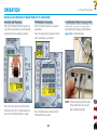
1
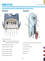
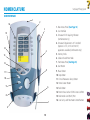
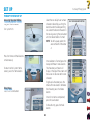
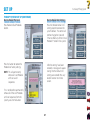
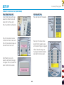
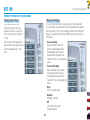
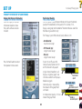
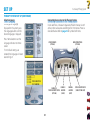
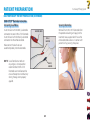
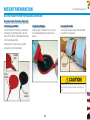
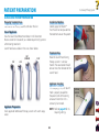
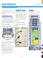
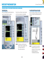
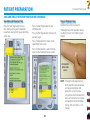
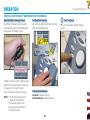
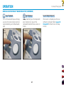
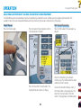
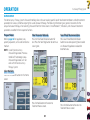
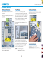
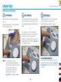
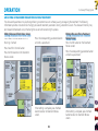
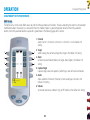
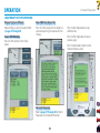
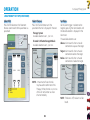
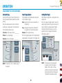
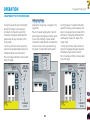
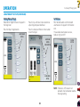
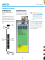
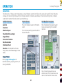
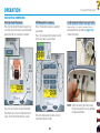
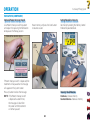
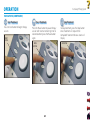
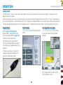
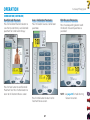
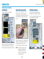
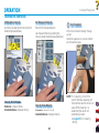
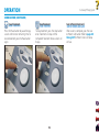
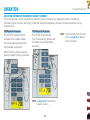
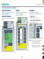
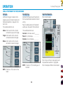
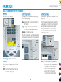
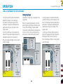
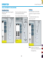
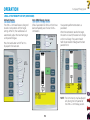
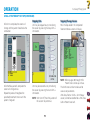
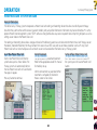
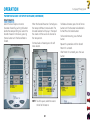
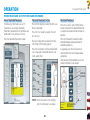
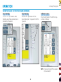
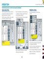
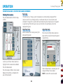
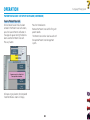
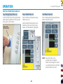
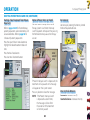
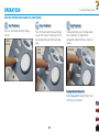
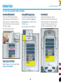
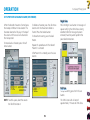
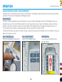
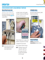
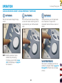
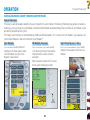
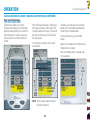
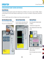
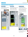
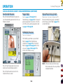
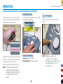
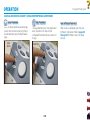
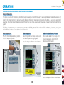
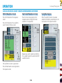
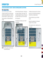
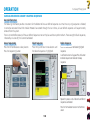
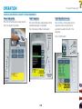
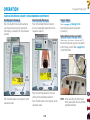
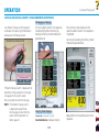
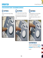
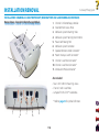
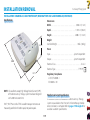
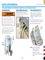
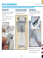
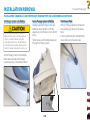
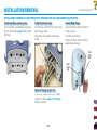
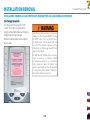
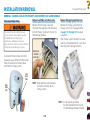
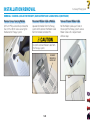
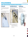
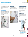
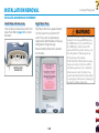
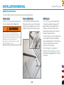
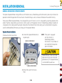
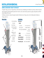
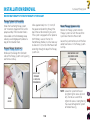
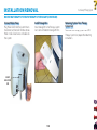
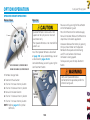
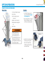
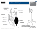
INSTALLATION/REMOVAL Vectra Genisys® Therapy System INSTALLATION CHANNEL 3/4 ELECTROTHERAPY, NiMH BATTERY AND LASER MODULE (CONTINUED) Set Therapy System onto Module Do not twist Ribbon Cable. If power is applied to the system with misalignment of pins or a twisted ribbon cable, the controlling electronics in the Module will be destroyed and possible damage to the System's internal components could occur. Secure Therapy System to Module Front Access Panel Carefully place the Therapy System and Module on one side. With a #1 Phillips Screwdriver, install the four 4 mm x 20 mm screws. Tighten screws until the Module does not move on the Therapy System. With a #1 Phillips Screwdriver, remove the screw retaining the existing Front Access Panel. Install Lanyard to the new Extended Front Access Panel using the same screw. Set the Therapy System on the Module. Make certain the Feet of the Therapy System are resting in the Module Indents. 120