1
Moving
Rehabilitation
Forward™
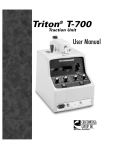
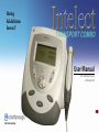
User Manual
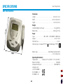
2738- Combination Ultrasound
and Stimulation Unit
ISO 13485 Certified
TABLE OF CONTENTS
Intelect® Transport Combo
FOREWORD . . . . . . . . . . . . . . . . . . . . . . . . . . . . . . . . . . . . . . . . . . 1
PRODUCT DESCRIPTION . . . . . . . . . . . . . . . . . . . . . . . . . . . . 1
SAFETY PRECAUTIONS . . . . . . . . . . . . . . . . . . . . . . . . . . . . . . . 2
PRECAUTIONARY DEFINITIONS . . . . . . . . . . . . . . . . . . . . . 2
CAUTIONS . . . . . . . . . . . . . . . . . . . . . . . . . . . . . . . . . . . . . . . . . 3
WARNINGS . . . . . . . . . . . . . . . . . . . . . . . . . . . . . . . . . . . . . . . . . 5
DANGERS . . . . . . . . . . . . . . . . . . . . . . . . . . . . . . . . . . . . . . . . . . 7
INDICATIONS, CONTRAINDICATIONS,
AND ADVERSE EFFECTS FOR ELECTROTHERAPY . . . . . 9
Indications for Russian, High Voltage Pulsed Current
(HVPC), Interferential, and Premodulated Waveforms . . . 9
Additional Indications for Interferential and
Premodulated Waveforms . . . . . . . . . . . . . . . . . . . . . . . . . . . . . 9
Contraindications . . . . . . . . . . . . . . . . . . . . . . . . . . . . . . . . . . . . . . 9
Additional Precautions . . . . . . . . . . . . . . . . . . . . . . . . . . . . . . . . . 9
Adverse Effects . . . . . . . . . . . . . . . . . . . . . . . . . . . . . . . . . . . . . . . 10
INDICATIONS, CONTRAINDICATIONS, AND ADVERSE
EFFECTS FOR ULTRASOUND THERAPY . . . . . . . . . . . . . . 11
Indications for Ultrasound . . . . . . . . . . . . . . . . . . . . . . . . . . . . 11
Contraindications . . . . . . . . . . . . . . . . . . . . . . . . . . . . . . . . . . . . . 11
Additional Precautions . . . . . . . . . . . . . . . . . . . . . . . . . . . . . . . . 11
Potential for Burns . . . . . . . . . . . . . . . . . . . . . . . . . . . . . . . . . . . . 12
Preventing Overheating of the Sound Heads . . . . . . . . . . 12
Preventing Adverse Effects . . . . . . . . . . . . . . . . . . . . . . . . . . . . 12
OVERVIEW . . . . . . . . . . . . . . . . . . . . . . . . . . . . . . . . . . . . . . . . . . 14
Common Terms . . . . . . . . . . . . . . . . . . . . . . . . . . . . . . . . . . . . . . 14
Description of Ultrasonic Field . . . . . . . . . . . . . . . . . . . . . . . . 19
NOMENCLATURE . . . . . . . . . . . . . . . . . . . . . . . . . . . . . . . . . . . . 20
SPECIFICATIONS . . . . . . . . . . . . . . . . . . . . . . . . . . . . . . . . . . . . 24
UNIT SPECIFICATIONS . . . . . . . . . . . . . . . . . . . . . . . . . . . . . 24
WAVEFORM SPECIFICATIONS . . . . . . . . . . . . . . . . . . . . . . . . 25
ULTRASOUND TECHNICAL SPECiFiCATiONS . . . . . . . . . 27
SOUND HEAD SPECIFICATIONS . . . . . . . . . . . . . . . . . . . . . 28
electromagnetic compatibility tables . . . . . . . 29
SETUP . . . . . . . . . . . . . . . . . . . . . . . . . . . . . . . . . . . . . . . . . . . . . . 31
MOUNTING THE UNIT ON THE WALL . . . . . . . . . . . . . . . . 31
INSTALLING THE BATTERY PACK . . . . . . . . . . . . . . . . . . . 35
CHARGING THE BATTERY PACK . . . . . . . . . . . . . . . . . . . . . 37
USING THE BATTERY PACK . . . . . . . . . . . . . . . . . . . . . . . . . 37
PATIENT PREPARATION . . . . . . . . . . . . . . . . . . . . . . . . . . . . . . 38
ELECTROTHERAPY PATIENT PREPARATION . . . . . . . . . 38
Electrode Placement . . . . . . . . . . . . . . . . . . . . . . . . . . . . . . . . . . 38
DURA-STICK® Electrodes . . . . . . . . . . . . . . . . . . . . . . . . . . . . . . 39
Reusable Carbon Electrodes (Optional) . . . . . . . . . . . . . . . . 39
DURA-STICK® Electrode Instructions . . . . . . . . . . . . . . . . . . 40
Connecting Lead Wires . . . . . . . . . . . . . . . . . . . . . . . . . . . . . . . 40
Reusable Carbon Electrodes (Optional) . . . . . . . . . . . . . . . . 41
Connecting Lead Wires . . . . . . . . . . . . . . . . . . . . . . . . . . . . . . . 41
Conductive Medium . . . . . . . . . . . . . . . . . . . . . . . . . . . . . . . . . . 41
Securing Electrodes . . . . . . . . . . . . . . . . . . . . . . . . . . . . . . . . . . . 41
ULTRASOUND THERAPY PATIENT PREPARATION . . . . 42
i
TABLE OF CONTENTS
Intelect® Transport Combo
OPERATION . . . . . . . . . . . . . . . . . . . . . . . . . . . . . . . . . . . . . . . . . 43
STARTING, STOPPING, AND INTERRUPTING
ELECTROTHERAPY . . . . . . . . . . . . . . . . . . . . . . . . . . . . . . . . 43
STARTING, STOPPING, AND INTERRUPTING
ULTRASOUND THERAPY . . . . . . . . . . . . . . . . . . . . . . . . . . . 48
STARTING, STOPPING, AND INTERRUPTING
COMBINATION THERAPY . . . . . . . . . . . . . . . . . . . . . . . . . . . 52
CREATING A USER PROTOCOL FOR
ELECTROTHERAPY . . . . . . . . . . . . . . . . . . . . . . . . . . . . . . . . 56
CREATING A USER PROTOCOL FOR ULTRASOUND
THERAPY . . . . . . . . . . . . . . . . . . . . . . . . . . . . . . . . . . . . . . . . . 58
CREATING A USER PROTOCOL FOR COMBINATION
THERAPY . . . . . . . . . . . . . . . . . . . . . . . . . . . . . . . . . . . . . . . . . . 60
USING PROTOCOLS . . . . . . . . . . . . . . . . . . . . . . . . . . . . . . . . 63
SYSTEM UTILITIES . . . . . . . . . . . . . . . . . . . . . . . . . . . . . . . . . 65
Audible Tones . . . . . . . . . . . . . . . . . . . . . . . . . . . . . . . . . . . . . . . . 65
Changing Protocol Parameters . . . . . . . . . . . . . . . . . . . . . . . 65
Changing Default Protocols for Electrotherapy . . . . . . . . . . . . . . . 66
Changing Default Protocols for Ultrasound Therapy . . . 68
Changing Default Protocolsfor Combination Therapy . . 69
Brightening or Dimming the LCD . . . . . . . . . . . . . . . . . . . . . 72
Restoring Factory Protocols . . . . . . . . . . . . . . . . . . . . . . . . . . 73
Changing Languages . . . . . . . . . . . . . . . . . . . . . . . . . . . . . . . . . 74
Restoring Factory Settings . . . . . . . . . . . . . . . . . . . . . . . . . . . . 75
Viewing Unit Version Information . . . . . . . . . . . . . . . . . . . . . . 76
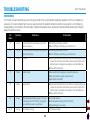
TROUBLESHOOTING . . . . . . . . . . . . . . . . . . . . . . . . . . . . . . . . . 78
ERROR CODES . . . . . . . . . . . . . . . . . . . . . . . . . . . . . . . . . . . . . 78
TROUBLESHOOTING THE DISPLAY AND ERROR
MESSAGES . . . . . . . . . . . . . . . . . . . . . . . . . . . . . . . . . . . . . . . . 80
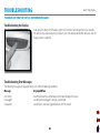
Troubleshooting the Display . . . . . . . . . . . . . . . . . . . . . . . . . . 80
Troubleshooting Error Messages . . . . . . . . . . . . . . . . . . . . . . 80
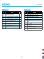
ACCESSORIES . . . . . . . . . . . . . . . . . . . . . . . . . . . . . . . . . . . . . . . 81
Standard Accessories . . . . . . . . . . . . . . . . . . . . . . . . . . . . . . . . . 81
Optional Accessories . . . . . . . . . . . . . . . . . . . . . . . . . . . . . . . . . 81
MAINTENANCE . . . . . . . . . . . . . . . . . . . . . . . . . . . . . . . . . . . . . . 82
MAINTAINING THE UNIT . . . . . . . . . . . . . . . . . . . . . . . . . . . 82
Cleaning the Unit and the Accessories . . . . . . . . . . . . . . . . 82
FACTORY SERVICE . . . . . . . . . . . . . . . . . . . . . . . . . . . . . . . . . 83
WARRANTY . . . . . . . . . . . . . . . . . . . . . . . . . . . . . . . . . . . . . . . . . 84
ii
FOREWORD
Intelect® Transport Combo
This manual has been written for the users of the Intelect Transport Combo units. It contains general information on the operation,
precautionary practices, and maintenance information. In order to maximize use, efficiency, and the life of the unit, read this manual
thoroughly and become familiar with the controls, as well as the accessories before operating the system.
Specifications put forth in this manual were in effect at the time of publication. However, owing to DJO, LLC's policy of continual
improvement, changes to these specifications may be made at any time without obligation on the part of DJO, LLC.
Before administering any treatment to a patient, the users of this equipment should read, understand, and follow the information
contained in this manual for each mode of treatment available, as well as the indications, contraindications, warnings, and precautions.
Consult other resources for additional information regarding the application of electrotherapy.
Product Description
The Intelect Transport Combo, designed and manufactured by DJO, LLC, offers a new dimension in clinical electrotherapy and ultrasound
made possible by software design and digital signal processing.
Effectiveness of this treatment is dependent upon correct use. If treatment times are exceeded, the therapy may not result in positive
clinical outcomes.
Stay current with the latest clinical developments in the field of electrotherapy. Observe all applicable precautionary measures for
treatment.
Keep informed of appropriate indications and contraindications for the use of electrotherapy and ultrasound.
This equipment is to be used only under the prescription and supervision of a licensed practitioner.
©2010 DJO, LLC Vista, California, USA. Any use of editorial, pictorial, or layout composition of this publication without express written consent from DJO, LLC is strictly
prohibited. This publication was written, illustrated, and prepared for distribution by DJO, LLC.
1
Safety precautions
Intelect® Transport Combo
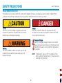
Precautionary Definitions
The precautionary instructions found in this section and throughout this manual are indicated by specific symbols. Understand these
symbols and their definitions before operating this equipment. The definition of these symbols are as follows:
Caution
Text with a “CAUTION” indicator will explain possible safety
infractions that could have the potential to cause minor to
moderate injury or damage to equipment.
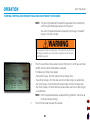
Danger
Text with a “DANGER” indicator will explain possible safety
infractions that are imminently hazardous situations that would
result in death or serious injury.
Dangerous Voltage
Text with a “Dangerous Voltage” indicator serves to inform
the user of possible hazards resulting in the electrical charge
delivered to the patient in certain treatment configurations
of waveforms.
Warning
Text with a “WARNING” indicator will explain possible safety
infractions that will potentially cause serious injury and
equipment damage.
NOTE: Throughout this manual, “NOTE” may be found. These
Notes are helpful information to aid in the particular area
or function being described.
2
Safety precautions
Intelect® Transport Combo
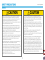
cautions
• The Intelect Transport Combo is not designed to prevent the
• Read, understand, and practice the precautionary and operating
ingress of water or liquids. Ingress of water or liquids could cause
malfunction of internal components of the system and therefore
create a risk of injury to the patient.
• DO NOT permit any foreign materials or liquids to enter the unit.
Take care to prevent any foreign materials including, but not limited
to, inflammables, water, and metallic objects from entering the unit.
These may cause unit damage, malfunction, electrical shock, fire, or
personal injury.
• Handle the applicator with care. Inappropriate handling of the
applicator may adversely affect its characteristics.
• Before each use, inspect the applicator for cracks, which may allow
the ingress of conductive fluid.
• This equipment generates, uses, and can radiate radio frequency
energy and, if not installed and used in accordance with the
instructions, may cause harmful interference to other devices in
the vicinity. However, there is no guarantee that interference will
not occur in a particular installation. Harmful interference to other
devices can be determined by turning this equipment on and off.
Try to correct the interference using one or more of the following:
reorient or relocate the receiving device, increase the separation
between the equipment, connect the equipment to an outlet on a
different circuit from that to which the other device(s) are connected
and consult the factory field service technician for help.
instructions. Know the limitations and hazards associated with
using any electrical stimulation or ultrasound device. Observe the
precautionary and operational decals placed on the unit.
• DO NOT operate the Intelect Transport Combo unit when connected
to any unit other than DJO, LLC devices.
• DO NOT operate this unit in an environment where other devices
are being used that intentionally radiate electromagnetic energy in
an unshielded manner. Portable and mobile RF communications
equipment can affect Medical Electrical Equipment.
• DO NOT use sharp objects such as a pencil point or ballpoint pen to
operate the buttons on the control panel.
• This unit should be operated, transported, and stored in temperatures
between 59° F and 104° F (15° C and 40° C), with relative humidity
ranging from 30%-60%, and where the atmospheric pressure is
between 950 h Pa and 1050 h Pa.
• The Intelect battery pack is designed for use only with Chattanooga
Intelect Transport Stim, Combo and Ultrasound systems.
• The unit should be routinely checked before each use to determine
that all controls function normally; especially that the intensity control
properly adjusts the intensity of the electrotherapy and ultrasonic
power output in a stable manner. Also, determine that the treatment
time control actually terminates electrotherapy and ultrasonic power
output when the timer reaches zero.
• Inspect cables and connectors before each use.
3
Safety precautions
Intelect® Transport Combo
cautions (continued)
• DO NOT remove the cover. This may cause unit damage,
• Where the integrity of the external protective earth conductor
malfunction, electrical shock, fire, or personal injury. There are
no user-serviceable parts inside the unit. If a malfunction occurs,
discontinue use immediately and consult the dealer for repair
service.
• Failure to use and maintain the Intelect Transport Combo and its
accessories in accordance with the instructions outlined in this
manual will invalidate your warranty.
• Nylatex® Wraps contain dry natural rubber and may cause allergic
reactions in patients with allergies to latex.
arrangement is in doubt, equipment shall be operated from its
internal electrical power source.
• Using a high intensity electrotherapy setting in conjunction with
high intensity ultrasound setting may cause the unit to reset.
• The battery pack should be removed when storing the unit for
extended periods of time.
• DO NOT disassemble, modify, or remodel the unit or accessories.
This may cause unit damage, malfunction, electrical shock, fire, or
personal injury.
4
Safety precautions
Intelect® Transport Combo
Warnings
• These devices are restricted to sale by, or on the order of, a physician
• Stimulation should not be applied over the anterior neck or mouth.
or licensed practitioner. This device should be used only under the
continued supervision of a physician or licensed practitioner.
• Make certain the unit is electrically grounded by connecting only to a
grounded electrical service receptacle conforming to the applicable
national and local electrical codes.
• Care must be taken when operating this equipment around other
equipment. Potential electromagnetic or other interference could
occur to this or to the other equipment. Try to minimize this
interference by not using other equipment in conjunction with it.
(i.e. cell phones, etc.)
• The user must keep the device out of the reach of children.
• Powered muscle stimulators should be used only with the leads and
electrodes recommended for use by the manufacturer.
• Before administering any treatment to a patient you should become
acquainted with the operating procedures for each mode of
treatment available, as well as the indications, contraindications,
warnings, and precautions. Consult other resources for additional
information regarding the application of electrotherapy and
ultrasound.
• To prevent electrical shock, disconnect the unit from the power
source before attempting any maintenance procedures.
• Keep electrodes separated during treatment. Electrodes in contact
with each other could result in improper stimulation or skin burns.
• Long term effects of chronic electrical stimulation are unknown.
Severe spasm of the laryngeal and pharyngeal muscles may occur
and the contractions may be strong enough to close the airway or
cause difficulty in breathing.
• Stimulation should not be applied transthoracically because the
introduction of electrical current into the heart may cause cardiac
arrhythmia.
• Stimulation should not be applied over swollen, infected, and
inflamed areas or skin eruptions, e.g., phlebitis, thrombophlebitis,
varicose veins, etc.
• Stimulation should not be applied over, or in proximity to, cancerous
lesions.
• Output current density is inversely related to electrode size. Improper
application may result in patient injury.
• Always keep the sound head in constant motion.
• Always keep the sound head in full contact with the patient’s skin or
submerged under water when setting intensity.
• Use ample conductive gel to ensure good coupling throughout the
treatment. If needed, apply when setting intensity.
• Be sure to read all instructions for operation before treating a patient.
• Dispose of all products in accordance with local and national
regulations and codes.
5
Safety precautions
Intelect® Transport Combo
Warnings (continued)
• Use of controls, adjustments, or performance of procedures other
than those specified herein may result in hazardous exposure to
ultrasonic energy.
• Use of controls or adjustments or performance of procedures other
than those specified herein may result in hazardous conditions
causing damage to the battery pack or cells.
• To prevent electrical shock, disconnect the battery pack from the
system before attempting any maintenance procedures.
• Do not drop the applicator on hard surfaces. Do not cool an
overheated sound head with ice water or ice packs. Do not allow the
sound head to reach maximum temperatures repeatedly. All of these
conditions are likely to damage the sound head crystal. Damage
resulting from these conditions is not covered under the warranty.
• In the event that an Error message or Warning appears beginning
with a 2 or 3, immediately stop all use of the unit and contact the
dealer or DJO, LLC for service. Errors and Warnings in these categories
indicate an internal problem with the unit that must be tested by
DJO, LLC or a Field Service Technician certified by DJO, LLC before any
further operation or use of the system.
• Use of a unit that indicates an Error or Warning in these categories
may pose a risk of injury to the patient, user, or extensive internal
damage to the system.
• Do not turn the unit on or off while it is connected to the patient.
• Do not apply the Ultrasound Applicator to the patient during the
Head Warming period. Applicator must remain in Applicator Hook
duing the Head Warming period.
• Use only accessories that are specially designed for this unit. Do
not use accessories manufactured by other companies on this unit.
DJO, LLC is not responsible for any consequence resulting from
using products manufactured by other companies. The use of other
accessories or cables may result in increased emissions or decreased
immunity of this unit.
6
Safety precautions
Intelect® Transport Combo
Dangers
• Stimulus delivered by the waveforms of this device,
Incorrect voltage may cause unit damage, malfunction,
electrical shock, fire, or personal injury. Your unit was
constructed to operate only on the electrical voltage
specified on the Voltage Rating and Serial Number Plate.
Contact your DJO, LLC dealer if the unit is not properly
rated.
• NiMH Batteries contain Class E corrosive materials. In the
event of battery cell rupture or leakage, handle battery
pack wearing neoprene or natural rubber gloves. Contents
of a ruptured or leaking battery can cause respiratory
irritation. Hypersensitivity to nickel can cause allergic
pulmonary asthma. Contents of cell coming in contact
with skin can cause skin irritation and/or chemical burns.
• Never, under any circumstances, open the battery pack
housing or cells. Should an individual battery from
a battery pack become disassembled, spontaneous
combustion of the negative electrode is possible. There
can be a delay between exposure to air and spontaneous
combustion.
in certain configurations, will deliver a charge of 25
microcoulombs (µC) or greater per pulse and may be
sufficient to cause electrocution. Electrical current of this
magnitude must not flow through the thorax because it
may cause a cardiac arrhythmia.
• Patients with an implanted neurostimulation device
must not be treated with or be in close proximity to
any shortwave diathermy, microwave diathermy,
therapeutic ultrasound diathermy, or laser diathermy
anywhere on their body. Energy from diathermy
(shortwave, microwave, ultrasound, and laser) can be
transferred through the implanted neurostimulation
system, can cause tissue damage, and can result in
severe injury or death. Injury, damage, or death can
occur during diathermy therapy even if the implanted
neurostimulation system is turned “off.”
• DO NOT connect the unit to an electrical supply without
first verifying that the power supply is the correct voltage.
7
Safety precautions
Intelect® Transport Combo
Dangers (continued)
• Charge the battery pack according to the instructions found in this
manual. Never attempt to charge the battery pack on any other
charging mechanism.
• Use the battery pack only with the Intelect Transport Series units.
• Do not reverse the polarity of the battery pack. Doing so can increase
the individual cell temperature and cause cell rupture or leakage.
• Never dispose of the battery pack in fire. Never short circuit the
battery pack. The battery pack may explode, ignite, leak, or get hot
causing serious personal injury.
• Dispose of NiMH batteries according to national, state, and local
codes and regulations.
8
Safety precautions
Intelect® Transport Combo
Indications, Contraindications, and Adverse Effects for electrotherapy
• Electrode placements must be avoided that apply current to the
Indications for Russian, High Voltage Pulsed Current (HVPC),
carotid sinus region (anterior neck) or transcereberally (through
Interferential, and Premodulated Waveforms
the head).
• Relaxation of muscle spasms
• Safety has not been established for the use of therapeutic
• Prevention or retardation of disuse atrophy
electrical stimulation during pregnancy.
• Increase local blood circulation
•
Powered muscle stimulators should not be used on patients with
• Muscle re-education
cardiac demand pacemakers.
• Maintaining or increasing range of motion
• There should not be any use of waveforms on patients with
• Immediate post-surgical stimulation of calf muscles to prevent
cardiac demand pacemakers.
venous thrombosis
Additional Precautions
Additional Indications for Interferential and Premodulated
• Caution should be used for patients with suspected or diagnosed
Waveforms
heart problems.
• Symptomatic relief of chronic, intractable pain
• Caution should be used for patients with suspected or diagnosed
• Post-traumatic acute pain
epilepsy.
• Post-surgical acute pain
• Caution should be used in the presence of the following:
» When there is a tendency to hemorrhage following acute
Contraindications
trauma or fracture;
• This device should not be used for symptomatic local pain
» Following recent surgical procedures when muscle contraction
relief unless etiology is established or unless a pain syndrome
may disrupt the healing process
has been diagnosed.
»
Over
a menstruating or pregnant uterus
• This device should not be used when cancerous lesions are
» Over areas of the skin which lack normal sensation
present in the treatment area.
• This device should not be used when open wounds are
present in the treatment area.
• Other contraindications are patients suspected of carrying
serious infectious disease and or disease where it is advisable,
for general medical purposes, to suppress heat or fevers.
9
Safety precautions
Intelect® Transport Combo
Indications, Contraindications, and Adverse Effects for electrotherapy (continued)
• Some patients may experience skin irritation or hypersensitivity
due to the electrical stimulation or electrical conductive
medium. The irritation can usually be reduced by using an
alternative conductive medium or an alternative electrode
placement.
• Electrode placement and stimulation settings should be based
on the guidance of the prescribing practitioner.
• Powered muscle stimulators should be used only with the
lead wires and electrodes recommended for use by the
manufacturer.
• With waveforms, isolated cases of skin irritation may occur
at the site of electrode placement following long-term
application.
• The effectiveness of waveforms is highly dependent upon
patient selection by a person qualified in the management of
pain patients.
Adverse Effects
• Skin irritation and burns beneath the electrodes have been
reported with the use of powered muscle stimulators.
10
Safety precautions
Intelect® Transport Combo
Indications, Contraindications, and Adverse Effects for ultrasound Therapy
Indications for Ultrasound
Application of therapeutic deep heat for the treatment of selected
sub-chronic and chronic medical conditions such as:
• Relief of pain, muscle spasms and joint contractures
• Relief of pain, muscle spasms and joint contractures that may be
associated with:
• Adhesive capsulitis
• Bursitis with slight calcification
• Myositis
• Soft tissue injuries
• Shortened tendons due to past injuries and scar tissues
• Relief of sub-chronic and chronic pain and joint contractures
resulting from:
• Capsular tightness
• Capsular scarring
• Over the thoracic area if the patient is using a cardiac pacemaker.
• Over a healing fracture.
• Over or applied to the eye.
• Over a pregnant uterus.
• On ischemic tissues in individuals with vascular disease where
the blood supply would be unable to follow the increase in
metabolic demand and tissue necrosis might result.
Additional Precautions
Additional precaution should be used when the ultrasound is used
on patients with the following conditions:
• Over an area of the spinal cord following a laminectomy (i.e., when major covering tissues have been removed).
• Over anesthetic areas.
• On patients with hemorrhagic diatheses.
Contraindications
This device should not be used:
• For symptomatic local pain relief unless etiology is established or
unless a pain syndrome has been diagnosed.
• When cancerous lesions are present in the treatment area.
• When open wounds are present in the treatment area.
• On patients suspected of carrying serious infectious disease and
or disease where it is advisable, for general medical purposes, to suppress heat or fevers.
• Over or near bone growth centers until bone growth is complete.
11
Patients with an implanted neurostimulation or defibrillator
device must not be treated with or be in close proximity to
any shortwave diathermy, microwave diathermy, therapeutic
ultrasound diathermy or laser diathermy anywhere on
their body. Energy from diathermy (shortwave, microwave,
ultrasound, and laser) can be transferred through the
implanted neurostimulation system, can cause tissue damage
and can result in severe injury or death. Injury, damage
or death can occur during diathermy therapy even if the
implanted neurostimulation system is turned “off.”
Safety precautions
Intelect® Transport Combo
Indications, Contraindications, and Adverse Effects for ultrasound (continued)
• You can also reduce the power or duty cycle during the
Potential for Burns
treatment if you are treating an area where it is difficult to obtain
It is possible for ultrasound therapy to cause burns if the therapy is
good coupling.
not properly performed. Skin burns can result from one or more of
Preventing Adverse Effects
the following:
Perform the following procedures to avoid the negative effects of
• If the intensity (power) is too high.
ultrasound therapy.
• If you are using too low a frequency.
Sound Head Movement
• Using a stationary technique (holding the sound head in one
place).
If movement of the sound head is too slow, the patient may feel
• Moving the sound head too slowly.
periosteal pain characterized by a deep ache or pain. If motion is too
• Treating an area with sensory nerve damage (or the loss of
fast, or if the sound head does not maintain good contact with the
normal skin sensations).
skin, the therapeutic effect of the sound waves will be reduced and
• Desensitized areas can be overheated or burned without the
the sound head may overheat.
patient’s knowledge. Use extreme caution with these patients
Patient Susceptibility
(e.g., diabetes, neural damage, etc.).
Some patients are more sensitive to ultrasound output and may
• Bony prominences are especially vulnerable: they reflect sound
experience a reaction similar to a heat rash. Be sure to inspect the
waves and increase intensity to the periosteum.
treatment area during and following treatment. Discontinue if an
Preventing Overheating of the Sound Heads
adverse reaction occurs.
To prevent the sound head from becoming overheated, do the
Output Power
following:
Choose a lower watt setting to reduce output or select a pulsed
• Check to be sure proper contact is being made throughout the
duty cycle. Higher output levels have a greater potential for patient
treatment.
discomfort.
• When treating in water, make sure that the sound head is
completely under water.
• For direct coupling, you may need to apply more conductive gel
or lotion during the treatment to achieve better coupling.
12
Safety precautions
Intelect® Transport Combo
Indications, Contraindications, and Adverse Effects for ultrasound (continued)
Coupling
Coupling is described as contact between the sound head and
the treatment site and may be accomplished through the use
of a coupling agent, such as gel, lotion, or water (underwater
treatments only). Anything used as a coupling agent must be highly
conductive. Air is a very poor conductor of ultrasonic waves.
Head Max. Temp. Disclaimer
Head Max. Temp. is for the protection of the equipment, not for the
protection of the patient. For more information, see page 80.
13
OVERVIEW
Intelect® Transport Combo
The Intelect Transport Combo, designed and manufactured by DJO, LLC, offers a new dimension in portable electrotherapy and ultrasound
made possible by advanced software design and digital signal processing. The result is a unit with extraordinary versatility based on
simplicity of operation.
The Intelect Transport Combo offers "On the Go" clinical electrotherapy and ultrasound. The unit provides an innovative case design, with a
logical control system and a large, easy to read graphical LCD. User defined protocols allow you to customize any treatment to the specific
needs of your patient. The repositional base allows the unit to be configured for desktop or wall-mount use.
The following features are available on the Intelect Transport Combo:
• Two channels of electrotherapy stimulation output
• Four waveforms - Russian, High Voltage Pulsed Current (HVPC), Interferential and Premodulated
• 1 or 3.3 MHz frequencies for each applicator (excluding the 1 cm2 sound head)
• Four available sound heads: 1 cm2, 2 cm2, 5 cm2, and 10 cm2
• Fifteen user-defined memory positions
• Lightweight design
• Battery powered option
Common Terms
Applicator - This apparatus is the hand held assembly used to deliver ultrasonic energy. The applicator includes the sound head,
transducer, and related electronics.
Accommodation - This condition is where nerves lose their ability (sensitivity) to respond to electrotherapy.
Amplitude Modulation (Ampl. Mod.) - Amplitude Modulation is an increase and decrease in intensity during treatment. For example, at
an 80% amplitude modulation, with the intensity set to 10 mA, the intensity decreases to 2 mA, and then increases to 10 mA throughout
the treatment. The available amplitude modulations are 40%, 60%, 80%, 100%, and Static (none).
14
OVERVIEW
Intelect® Transport Combo
Beam Non-Uniformity Ratio (BNR) – By nature, an ultrasound beam is not homogeneous. The BNR is a ratio of the highest intensity
found in the beam field to the average intensity as indicated on the output display of the unit. This measure may not exceed 5.0:1. Because
of the areas of increased intensity, the sound head is moved continuously during the treatment.
Beat Fixed - Associated with the Interferential waveform, Beat Fixed is the parameter at which the beat frequency remains constant. When
the Sweep setting is turned off, you must select a fixed beat for the therapy session. The available settings for Beat Fixed are 1 to 200 Hz.
Beat Frequency - Associated with the Interferential waveform, Beat Frequency is the frequency at which the amplitude of the current
increases and decreases. The beat frequency is considered to be the therapeutic frequency and is measured in hertz (Hz).
Beat High - During a sweep, the Beat High setting is the highest number to which the beat frequency increases. The available range for
the Beat High parameter is 2 to 200 Hz. This parameter is unique to the Premodulated and Interferential waveforms.
Beat Low - During a sweep, the Beat Low setting is the lowest number to which the beat frequency decreases. The available range for the
Beat Low parameter is 1 to 199 Hz. This parameter is unique to the Premodulated and Interferential waveforms.
Burst - A burst is a series of pulses at a predetermined pulse frequency.
Burst Frequency (Freq.) - This is the number of bursts per second (bps). The available burst frequencies on the Intelect Transport Combo
are 1 to 10 bps.
Carrier Frequency (Freq.) - Associated with the Interferential, Premodulated and Russian waveforms, Carrier Frequency is the frequency
of the un-modulated medium frequency current. The carrier frequency for Premodulated and Russian is at a fixed frequency of 2500 Hz.
The available carrier frequencies for Interferential are 2000, 2500, 4000 and 5000 Hz.
CC/CV - This is the abbreviation for Constant Current/Constant Voltage. Constant current is a stimulator capable of delivering an electric
current that flows at the same amplitude regardless of changes in tissue impedance over time. Constant voltage is a stimulator capable of
delivering a source of voltage at the same amplitude regardless of changes in tissue impedance over time. Keep in mind that the amount
of stimulation is directly proportional to the current.
Channel Mode - The available channel modes are Single Channel (in which electrotherapy is distributed from one channel), Reciprocal
(where electrotherapy alternates between channels), and Co-Contract (where electrotherapy is distributed from both channels at the same
time).
15
OVERVIEW
Intelect® Transport Combo
Clinical Library- Select this button to access the following functions: Retrieve User Protocols, Restore Factory Settings, Restore Factory
Protocols, Language and View Unit Information.
Collimating (Coll)- The shape of the ultrasound beam. While neither focused nor dispersed, this ultrasound beam resembles a column
when applied from the unit through the sound head.
Continuous Mode – The output of the ultrasound is not interrupted during the treatment time. This mode imparts the most energy to
the tissues and is used when a maximal effect is desired. (See Duty Cycle).
Coupling Media – An agent used to insure that the ultrasound is transmitted from the sound head to the tissue to be treated. Gels or
lotions labeled for therapeutic ultrasound use are recommended.
Cycle Time - Cycle Time is the alternating time which the current is "on" and "off." Using the 10/30 setting as an example, the current is on
for 10 seconds and off for 30. The available cycle times are Continuous, 5/5, 4/12, 10/10, 10/20, 10/30, and 10/50.
Display - Available only on the High Voltage Pulsed Current (HVPC) waveform, the Display feature allows you to change the displayed
Intensity parameter from Volts to Peak Current (Amps).
Duty Cycle - This is the ratio of the “On” time to “Total” time of the cycle, expressed as a percentage. The duty cycle describes the pulsed
modes of electric stimulation and ultrasound. The lower the percentage, the lower temporal average intensity. 100% is continuous
electrotherapy. The available Duty Cycles are 10, 20, 30, 40, 50%.
Effective Radiating Area (ERA) – A measure of the ultrasound beam made underwater, 5 mm from the radiating surface of the sound
head. The ERA is always smaller than the geometric area of the sound head, but should be as close as possible. This measurement is used
to calculate the ultrasound intensity in W/cm2.
Frequency (Electrotherapy) - Frequency is the number of times per second a pulse, cycle, burst, or beat will repeat itself. The unit is
selectable from 1-200 Hz (beat), 20-100 Hz (burst), and 2000-5000 Hz (carrier).
Frequency (Ultrasound) – Selectable to 1 or 3.3 MHz with the 2 cm2, 5 cm2, or 10 cm2 sound head (excluding the 1 cm2 sound head).
The lower the frequency, the longer the wavelength, the deeper the penetration of ultrasound.
Frequency Modulation (Freq. Mod.) - This is the rhythm at which a frequency changes. The available frequency modulations are 0 to
250 Hz in increments of 5 Hz.
16
OVERVIEW
Intelect® Transport Combo
Intensity (Electrotherapy) - Intensity is the output of electrotherapy distributed by the unit to the patient. Depending on the waveform,
intensity is measured in milliamps (mA) or volts (V).
Intensity (Ultrasound) – Ultrasound power delivered to the patient expressed in total power as watts (W) or in terms of the sound head’s
effective radiating area, watts per centimeter squared (W/cm2).
LCD- The LCD (Liquid Crystal Display) allows the user to view and monitor the information displayed during ultrasound therapy. The
following information is displayed on the LCD: Frequency, Duty Cycle, Power and Treatment Time.
Lead Zirconate Titanate – A synthetic crystal used to create the ultrasound beam by vibrating 1000000 (1 MHz) or 3300000 (3.3 MHz)
times per second. This type of crystal is both durable and efficient in its functions.
Leadwires - The leadwires consist of the main plugs that are connected to the unit, and 4 leads (2 black and 2 red) that connect to
electrodes.
Medium Frequency Current - These are the currents used by Interferential, Premodulated, and Russian waveforms that is higher than
1000 Hz, but lower than 5000 Hz.
Operating Channels - Operating Channels are the paths by which the electrotherapy is distributed from the unit to the patient. The unit
provides two channels of electrical stimulation.
Phase Duration - This is the time in which the current flows in one direction only. Phase duration is the determined period of time
elapsing from the beginning to the end of one phase, usually expressed in microseconds (µsec) or milliseconds (ms).
Polarity - Polarity refers to the charge of an individual lead: positive or negative.
Polarity Reversal - This is a feature available on the unit in which the polarity changes at a determined time.
Power – A measure of the intensity of the ultrasound delivered to the patient. The unit of measure is watts (W).
Protocol – A group of parameters (e.g., Frequency, Duty Cycle, etc.) unique to a form of therapy (i.e., electrotherapy or ultrasound).
Pulse Duration – Refers to the amount of time the ultrasound is being delivered in the pulsed mode. For example, in the 20% duty cycle
mode, the ultrasound is delivered for 2 msec and off for 8 msec (at 100 Hz) throughout the treatment period.
Pulse Frequency – The pulse frequency is the number of pulses per second and is expressed in hertz. The available pulse frequencies for
ultrasound therapy is 100 Hz.
17
OVERVIEW
Intelect® Transport Combo
Pulsed Mode (Electrotherapy) – This is an available mode on the unit in which electrotherapy is distributed intermittently.
Pulsed Mode (Ultrasound) – The output of the ultrasound is automatically interrupted during the treatment time. This limits the amount
of energy delivered to the tissues.
Ramp - Ramp is the gradual increase and decrease in current. The purpose of ramping up the current is to maximize patient comfort by
preventing the abrupt and sudden exposure to the current.
Sound Head – The aluminum face of the applicator that contacts the patient’s skin. It covers a transducer mechanism that converts
electrical energy to mechanical energy in the form of a vibrating crystal.
Sweep - This is the modulation of therapeutic frequency commonly used to prevent accommodation. Sweeps are measured in pulses per
second (pps) and Hertz (Hz).
Treatment Time – Measured in minutes and seconds, it is the suggested time in which therapy is given.
Vector - A vector is a geometrically descriptive feature used to increase the effective therapeutic current at the crossing point of
Interferential.
Vector Position - The available vector positions are 0 to 90 degrees.
Vector Scan - Measured in percentages, vector scans are the rhythmic changes of the position of vector. The available vector scans are
Manual, Auto 40% and Auto 100%.
Waveforms - Waveforms are current or voltage that is varied by time and are the geometrical descriptions of a DC, AC, or pulsed DC/AC
current. For more specifications and types of waveforms available on the Intelect Transport Combo, refer to the section entitled "Waveform
Specifications."
18
OVERVIEW
Intelect® Transport Combo
Description of Ultrasonic Field
The spatial distribution of the radiated field is essentially a collimated beam of the ultrasonic energy having a cross-sectional area of 8.5 cm2
for the 10 cm2 sound head when measured at a point 5 mm from the transducer face.
The energy distribution within the radiated field is 3.0 W/cm2 peak and it takes a generally conic shape, having decreasing intensity at
progressively increasing distance from the face of the transducer. This field distribution applies for the radiation emitted into the equivalent
of an infinite medium of distilled, degassed water at 86° F and with the line voltage variations in the range of 10% of the rated line voltage.
19
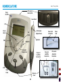
NOMENCLATURE
Intelect® Transport Combo
LCD Intensity/
Contrast Dial
Power
On/Off
Sound Head
LCD
Clinical
Library
LED Indicator
(Output Power)
Up
Arrow
TIME
Power Cord
Connection
Power
Cord
Applicator
INTENSITY
Back
Parameter
Display/Enter
STOP
Down
Arrow
PAUSE
Channel 1
Lead Wire
Connection
START
Accessory
Panel
20
Channel 2
Lead Wire
Connection
Ultrasound
Applicator
Connection
NOMENCLATURE
Intelect® Transport Combo
Power On/Off
The Power On/Off button controls the flow of electricity to the unit.
NOTE: Make certain there are no electrodes on the patient when turning the unit on or off.
LCD
The LCD (Liquid Crystal Display) allows the user to view and monitor the information displayed before, during, and after therapy.
Clinical Library
Select this button to access the following functions:
•Retrieve User Protocol
•
Restore Factory Settings
•
Restore Factory Protocols
•
Languages
•
View Unit Information
TIME
Press the Up or Down arrow buttons to set total treatment time of therapy.
Back
Use this button to return to the previous window.
STOP
Select this button to stop a treatment session.
Down Arrow
When the window displays a list of options, press the Down Arrow button to scroll down the list.
PAUSE
Use this button to pause the treatment session. To restart therapy, press the PAUSE button.
21
NOMENCLATURE
Intelect® Transport Combo
Sound Head
The aluminum face of the applicator that contacts the patient’s skin. It covers a transducer mechanism that converts electrical
energy to mechanical energy in the form of a vibrating crystal.
LED Indicator (Output Power)
When illuminated, this green light signifies that ultrasound energy is being distributed through the applicator.
Applicator
The hand held assembly used to deliver ultrasonic energy. The applicator includes the sound head, transducer, and related
electronics.
Accessory Panel
The Accessory Panel serves as a port of connection for the electrodes and ultrasound applicator.
Channel 1 Lead Wire Connection
This port serves as the connection point between the unit and the Channel 1 Lead Wire.
Channel 2 Lead Wire Connection
This port serves as the connection point between the unit and the Channel 2 Lead Wire.
Ultrasound Applicator Connection
This port serves as the connection point between the unit and the ultrasound applicator.
START
Select Start to begin a treatment session.
Parameter Display/Enter
Select this button to display the parameters of the waveform during treatment. Also, this button is used to accept the highlighted selection.
INTENSITY
Use the up or down arrow on the INTENSITY button to increase or decrease output power.
22
NOMENCLATURE
Intelect® Transport Combo
Up Arrow
When the window displays a list of options, press the Up Arrow button to scroll up the list.
Battery Indicator
When displayed on the LCD, this symbol indicates the battery pack option is present on the unit. This symbol also displays the
charge status of the battery.
LCD Intensity/Contrast Dial
If the intensity of the LCD display diminishes, turn the dial until the display contrast is optimal.
Charge Indicator
This symbol displays when the unit is connected to mains power and the battery pack is charging.
NOTE: During battery operation, if the unit is left on, but is not active for more than five minutes, it will power off to conserve battery power. To restore power, press the Power On/Off button.
23
SPECIFICATIONS
Intelect® Transport Combo
unit specifications
Dimensions
Length. . . . . . . . . . . . . . . . . . . . . . . . . . . . . . . . . . . . . . . . . . . 29.2 cm (11.5 in)
Width . . . . . . . . . . . . . . . . . . . . . . . . . . . . . . . . . . . . . . . . . . 25.7 cm (10.125 in)
Height. . . . . . . . . . . . . . . . . . . . . . . . . . . . . . . . . . . . . . . . . . . . 18.4 cm (7.25 in)
Leng
th
Weight
Standard Weight (with base). . . . . . . . . . . . . . . . . . . . . . . . 2.3 kg (5.07 lb)
Battery Pack. . . . . . . . . . . . . . . . . . . . . . . . . . . . . . . . . . . . . . . 0.85 kg (1.87 lb)
Power
Input. . . . . . . . . . . . . . . . . . . . . . 100 - 240 V - 1.0 A, 50/60 Hz 100 W Max
Output. . . . . . . . . . . . . . . . . . . . . . . . . . . . . . . . . . . . . . . . . . . . . . +24 V, 3.125 A
Electrical Class. . . . . . . . . . . . . . . . . . . . . . . . . . . . . . . . . . . . . . . . . . . . . . CLASS I
Electrical Type . .Ultrasound TYPE B,
Electrotherapy TYPE BF
Battery Type. . . . . . . . . . . . . . . . . . . . . . . . . . . Nickel Metal Hydride (NiMH)
. . . . . . . . . . . . . . . . . . . . . . . . . . . . . . . . . . . . . . . . . . . . . . . . . (1.2 V x 20 size AA)
Width
Operating Environment
Temperature. . . . . . . . . . . . Between 59° F and 104° F (15° C and 40° C)
Relative Humidity. . . . . . . . . . . . . . . . . . . . . . . . . . . . . . . . . . . . . . . . . 30%-60%
Atmospheric Pressure . . . . . . . . . . . . . . . . . . . . . . . . . . . . . . . 950-1050 h Pa
Complies with:
UL/IEC/EN 60601-1
IEC/EN 60601-1-2
IEC 60601-2-10
24
SPECIFICATIONS
Intelect® Transport Combo
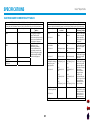
Waveform Specifications
Interferential
Premodulated
Premodulated current is a medium frequency waveform. Current
comes out of one channel (two electrodes). The current intensity
is modulated: it increases and decreases at a regular frequency
(the Beat Frequency).
Output Intensity. . . . . . . . . . . . . . . . . . . . . . . . . . . . . . . . . . . . . . . . . . . . . . . . 0-100 mA
Carrier Frequency. . . . . . . . . . . . . . . . . . . . . . . . . . . . . . . . . . . . . . . . 2500 Hz
Beat Fixed (Sweep Off ). . . . . . . . . . . . . . . . . . . . . . . . . . . . . . . . . . 1-200 Hz
Sweep Low Beat Frequency . . . . . . . . . . . . . . . . . . . . . . . . . . . . . 1-199 Hz
Sweep High Beat Frequency. . . . . . . . . . . . . . . . . . . . . . . . . . . . . 2-200 Hz
Cycle Time. . . . . . Continuous, 5/5, 4/12, 10/10, 10/20, 10/30, and 10/50
Mode Selection. . . . . . . . . . . . . . . . . . . . . . . . . . . . . . . . . . . . . . . . . . . . . . . CC or CV*
Treatment Time. . . . . . . . . . . . . . . . . . . . . . . . . . . . . . . . . . . . . . . . . . 1-60 min
Interferential current is a medium frequency waveform. Current is
distributed through two channels (four electrodes). The currents
cross each other in the body at the area requiring treatment.
The two currents interfere with each other at this crossing point,
resulting in a modulation of the intensity (the current intensity
increases and decreases at the beat frequency).
Carrier Frequency. . . . . . . . . . . . . . . . . . . . . . . . . . . . . . . . . . . 2000-5000 Hz
Beat Frequency. . . . . . . . . . . . . . . . . . . . . . . . . . . . . . . . . . . . . . . . . . 1-200 Hz
Sweep Time. . . . . . . . . . . . . . . . . . . . . . . . . . . . . . . . . . . . . . . . . . . . . 1-200 Hz
Sweep Low Beat Frequency . . . . . . . . . . . . . . . . . . . . . . . . . . . . . 1-199 Hz
Sweep High Beat Frequency. . . . . . . . . . . . . . . . . . . . . . . . . . . . . 2-200 Hz
Amplitude. . . . . . . . . . . . . . . . . . . . . . . . . . . . . . . . . . . . . . . . . . . . . . 0-100 mA
Treatment Time. . . . . . . . . . . . . . . . . . . . . . . . . . . . . . . . . . . . . . . . . . 1-60 min
Mode Selection. . . . . . . . . . . . . . . . . . . . . . . . . . . . . . . . . . . . . . . . . CC or CV*
*CC= Constant Current
CV= Constant Voltage
25
SPECIFICATIONS
Intelect® Transport Combo
Waveform Specifications (continued)
High Voltage Pulsed Current (HVPC)
Russian
The High Voltage Pulsed Current (HVPC) has a very brief pulse
duration characterized by two distinct peaks delivered at
high voltage. The waveform is monophasic (current flows in
one direction only). The high voltage causes a decreased skin
resistance making the current comfortable and easy to tolerate.
Output Intensity. . . . . . . . . . . . . . . . . . . . . . . . . . . . . . . . . . . . . . . . . . 0-500 V
Polarity. . . . . . . . . . . . . . . . . . . . . . . . . . . . . . . . . . . . . . . Positive or Negative
Ramp. . . . . . . . . . . . . . . . . . . . . . . . . . . . . . . . . . . 0.5 sec, 1 sec, 2 sec, 5 sec
Display. . . . . . . . . . . . . . . . . . . . . . . . . . . . . . . . . . . . . . Peak Current or Volts
Sweep. . . . . . . . . . . . . . Continuous, 80/120 pps, 1/120 pps, 1/10 pps
Frequency. . . . . . . . . . . . . . . . . . . . . . . . . . . . . . . . . . . . . . . . . . . . 10-120 pps
Cycle Time. . . . . . 5/5, 4/12, 10/10, 10/20, 10/30, 10/50, Continuous
Treatment Time. . . . . . . . . . . . . . . . . . . . . . . . . . . . . . . . . . . . . . . . . . 1-60 min
Russian Current is a sinusoidal waveform, delivered in bursts or
series of pulses. This method was claimed by its author (Kots)
to produce maximal muscle strengthening effects without
significant discomfort to the patient.
Output Intensity. . . . . . . . . . . . . . . . . . . . . . . . . . . . . . . . . . . . . . . . . . . . . . . . 0-100 mA
Channel Mode. . . . . . . . . . . . . . . . . . . . . Single, Reciprocal, and Co-Contract
Duty Cycle. . . . . . . . . . . . . . . . . . . . . . . . . . . . . . 10%, 20%, 30%, 40%, 50%
Mode Selection. . . . . . . . . . . . . . . . . . . . . . . . . . . . . . . . . . . . . . . . . . . . . . . CC or CV*
Cycle Time. . . . . 5/5, 4/12, 10/10, 10/20, 10/30, 10/50, and Continuous
Burst Frequency. . . . . . . . . . . . . . . . . . . . . . . . . . . . . . . . . . . . . . 20-100 bps
Ramp. . . . . . . . . . . . . . . . . . . . . . . . . . . . . . . . . . . . . . . . . . 0.5, 1, 2, and 5 sec
Treatment Time. . . . . . . . . . . . . . . . . . . . . . . . . . . . . . . . . . . . . . . . . . 1-60 min
*CC= Constant Current
CV= Constant Voltage
26
SPECIFICATIONS
Intelect® Transport Combo
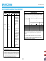
Ultrasound technical Specifications
Sound Heads. . . . . . . . . . . . . . . . . . . . . . . . . . . . . 1 cm2, 2 cm2, 5 cm2, 10 cm2
Duty Cycles
Pulsed. . . . . . . . . . . . . . . . . . . . . . . . . . . . . . . . . . . . . . . . . . . . . . . 10%, 20%, and 50%
Continuous. . . . . . . . . . . . . . . . . . . . . . . . . . . . . . . . . . . . . . . . . . . . . . . . . . . . . . . . . 100%
Pulse Frequency. . . . . . . . . . . . . . . . . . . . . . . . . . . . . . . . . . . . . . . . . . . . . . . . 100 Hz
Output accuracy. . . . . . . . . . . . . . . . . . . +/- 20% above 10% of maximum
Amplitude. . . . . . . . . . . . . . . . . . . . . . 0 to 2.5 W/cm2 in Continuous mode,
. . . . . . . . . . . . . . . . . . . . . . . . . . . . . . . . . . . . . . . . . . . . . 0-3 W/cm2 in pulsed modes
Temporal Peak to Average Ratios
. . . . . . . . . . . . . . . . . . . . . . . . . . . . . . . . . . . . . . . . . 2:1, +/- 20%, for 50% Duty Cycle
. . . . . . . . . . . . . . . . . . . . . . . . . . . . . . . . . . . . . . . . . 5:1, +/- 20%, for 20% Duty Cycle
. . . . . . . . . . . . . . . . . . . . . . . . . . . . . . . . . . . . . . . . . 9:1, +/- 20%, for 10% Duty Cycle
Maximum Treatment Time. . . . . . . . . . . . . . . . . . . . . . . . . . . . . . . 30 Minutes
Output
Pulsed. . . . . . . . . . . . . . . . . . . . . . . . . . . . . . . . . . . . . . . . . 1 MHz or 3.3 MHz signal,
modulated 100% by the 100 Hz rectangular wave with the selected Duty Cycle.
Continuous. . . . . . . . . . . . . . . . . . . . . . . . . . . 1 MHz or 3.3 MHz, nominal signal
that is activated as long as the timer is operating.
Timer Accuracy. . . . . . . . . . . . . . . . . . . . . . . . . . . . . . . . . . . . . . . . . +/-0.2 Minutes
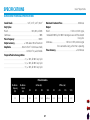
Pulse Duration
Modulation
Frequency
(Hz)
Modulation
Period
(ms)
100
10.000
On Times (ms)
Off Times (ms)
10%
20%
50%
100%
10%
20%
50%
100%
1.000
2.000
5.000
Continuous
9.000
8.000
5.000
0.000
27
SPECIFICATIONS
Intelect® Transport Combo
sound head Specifications
1 cm2 Sound Head
Frequency. . . . . . . . . . . . . . . . . . . . . . . . . . . . . . . . . . . . . . . . . . 3.3 MHz (all +/- 5%)
Power. . . . . . . . . . . . . . . . . . . . . . . . . . . . . . . . . . . . . . . . . . . . . . . . . . . 0 watt to 2 watts
Effective Radiating Area. . . . . . . . . . . . . . . . . . . . . . . . . . . . . . . . . 0.7 cm2 – 1 cm2
Maximum beam non-uniformity ratio. . . . . . . . . . . . . . . . . . . . . . . . . . . . . 5.0:1
Beam Type. . . . . . . . . . . . . . . . . . . . . . . . . . . . . . . . . . . . . . . . . . . . . . . . . . . Collimating
5 cm2 Sound Head
Frequency. . . . . . . . . . . . . . . . . . . . . . . . . . . . . . . . . . . 1 MHz, 3.3 MHz (all +/- 5%)
Power. . . . . . . . . . . . . . . . . . . . . . . . . . . . . . . . . . . . . . . . . . . . . . . . . . 0 watt to 10 watts
Effective Radiating Area. . . . . . . . . . . . . . . . . . . . . . . . . . . . . . . . . 3.5 cm2 – 5 cm2
Maximum beam non-uniformity ratio. . . . . . . . . . . . . . . . . . . . . . . . . . . . . 5.0:1
Beam Type. . . . . . . . . . . . . . . . . . . . . . . . . . . . . . . . . . . . . . . . . . . . . . . . . . . Collimating
2 cm2 Sound Head
Frequency. . . . . . . . . . . . . . . . . . . . . . . . . . . . . . . . . . . 1 MHz, 3.3 MHz (all +/- 5%)
Power. . . . . . . . . . . . . . . . . . . . . . . . . . . . . . . . . . . . . . . . . . . . . . . . . . . 0 watt to 4 watts
Effective Radiating Area. . . . . . . . . . . . . . . . . . . . . . . . . . . . . . . . . 1.4 cm2 – 2 cm2
Maximum beam non-uniformity ratio. . . . . . . . . . . . . . . . . . . . . . . . . . . . . 5.0:1
Beam Type. . . . . . . . . . . . . . . . . . . . . . . . . . . . . . . . . . . . . . . . . . . . . . . . . . . Collimating
10 cm2 Sound Head
Frequency. . . . . . . . . . . . . . . . . . . . . . . . . . . . . . . . . . . 1 MHz, 3.3 MHz (all +/- 5%)
Power. . . . . . . . . . . . . . . . . . . . . . . . . . . . . . . . . . . . . . . . . 1 MHz: 0 watt to 20 watts
.(0 to 15 watts if 2 channels of electrotherapy are used simultaneously)
. . . . . . . . . . . . . . . . . . . . . . . . . . . . . . . . . . . . . . . . . . . . . . 3.3 MHz: 0 watt to 10 watts
Effective Radiating Area. . . . . . . . . . . . . . . . . . . . . . . . . . . . . . . . 6.8 cm2 – 10 cm2
Maximum beam non-uniformity ratio. . . . . . . . . . . . . . . . . . . . . . . . . . . . . 5.0:1
Beam Type. . . . . . . . . . . . . . . . . . . . . . . . . . . . . . . . . . . . . . . . . . . . . . . . . . . Collimating
Head Warming Feature
The Head Warming feature of an Intelect Transport Combo
utilizes Ultrasound output resulting in warming of the Sound
Head to increase patient comfort.
With Head Warming enabled, ultrasound is emitted without
pressing the Start button. The Applicator LED will not illuminate
during the Head Warming period. US Channel will indicate "Head
Warming".
Output���������������������������������������������0 - 50% Cycling of maximum power
Frequency����������������������������������������������������������������������������������������������� 3.3 MHz
Sound Head Temperature ����������������85 °F - 110 °F (29.4 °C - 43.3 °C)
Do not apply the Ultrasound Applicator to the patient during the Head
Warming period. Applicator must remain in Applicator Hook duing the
Head Warming period.
28
SPECIFICATIONS
Intelect® Transport Combo
electromagnetic compatibility tables
Guidance and manufacturer’s declaration – electromagnetic immunity
The Intelect Transport Combo is intended for use in the electromagnetic environment specified below. The
customer or the user of the Intelect Transport Combo should assure that it is used in such an environment.
Immunity test
IEC 60601
Compliance level
Electromagnetic
test level
environment - guidance
Electrostatic discharge
±6kV contact
±6kV contact
Floors should be wood,
(ESD)
concrete or ceramic tile. If
±8kV air
±8kV air
floors are covered with
IEC 61000-4-2
synthetic material, the
relative humidity should
be at least 30%.
Electrical fast
±2kV for power supply
±2kV for power supply
Mains power quality
transient/burst
lines
lines
should be that of a typical
commercial or hospital
IEC 61000-4-4
±1kV for input/output
±1kV for input/output
environment.
lines
lines
Surge
±1kV differential mode
±1kV differential mode
Mains power quality
should be that of a typical
IEC 61000-4-5
±2kV common mode
±2kV common mode
commercial or hospital
environment.
<5% UT
Mains power quality
Voltage dips, short
<5% UT
(>95% dip in UT) for 0.5
should be that of a typical
interruptions and voltage (>95% dip in UT) for 0.5
cycle
cycle
commercial or hospital
variations on power
environment. If the user
supply input lines
40% UT
40% UT
of the Intelect Transport
IEC 61000-4-11
(60% dip in UT) for 5
(60% dip in UT) for 5
Combo requires
cycles
cycles
continued operation
during power mains
70% UT
70% UT
interruptions, it is
(30% dip in UT) for 25
(30% dip in UT) for 25
recommended that the
cycles
cycles
Intelect Transport Combo
be powered from an
<5% UT
<5% UT
uninterrupted power
(>95% dip in UT) for 5 sec (>95% dip in UT) for 5 sec supply or a battery.
Guidance and manufacturer’s declaration – electromagnetic emissions
The Intelect Transport Combo is intended for use in the electromagnetic environment specified below. The
customer or the user of the Intelect Transport Combo should assure that it is used in such an environment.
Emission tests
Compliance
Electromagnetic environment guidance
RF emissions
Group 1
The Intelect Transport Combo uses
CISPR 11
RF energy only for its internal
function. Therefore, its RF
emissions are very low and are not
likely to cause any interference in
nearby electronic equipment.
RF emissions
Class A
The Intelect Transport Combo is
CISPR 11
suitable for use in all
establishments, including
domestic establishments and
those directly connected to the
public low-voltage power supply
network that supplies buildings
used for domestic purposes.
Harmonic emissions
Class A
IEC 61000-3-2
Voltage fluctuations
Complies
IEC 61000-3-3
Power frequency
(50/60Hz) magnetic field
3 V/m
3 V/m
IEC 61000-4-8
NOTE UT is the a.c mains voltage prior to application of the test level.
29
Power frequency
magnetic fields should be
at levels characteristic of
a typical location in a
typical commercial or
hospital environment.
SPECIFICATIONS
Intelect® Transport Combo
electromagnetic compatibility tables (continued)
Recommended separation distances between portable and mobile RF communications equipment
and the Intelect Transport Combo
The Intelect Transport Combo is intended for use in an electromagnetic environment in which radiated RF
disturbances are controlled. The customer or the user of the Intelect Transport Combo can help prevent
electromagnetic interference by maintaining a minimum distance between portable and mobile RF
communications equipment (transmitters) and the Intelect Transport Combo as recommended below,
according to the maximum output power of the communications equipment.
Rated maximum output
Separation distance according to frequency of transmitter
power of transmitter
m
W
150 kHz to 80 MHz
80 MHz to 800 MHz
800 MHz to 2.5 GHz
Guidance and manufacturer’s declaration – electromagnetic immunity
The Intelect Transport Combo is intended for use in the electromagnetic environment specified below. The
customer or the user of the Intelect Transport Combo should assure that it is used in such an environment.
Immunity test
IEC 60601
Compliance level Electromagnetic environment test level
guidance
Portable and mobile RF
communications equipment
should be used no closer to any
part of the Intelect Transport
Combo, including cables, than
the recommended separation
distance calculated from the
equation applicable to the
frequency of the transmitter.
Conducted RF
3 Vrms
IEC 61000-4-6
150 kHz to 80 MHz
Radiated RF
3 V/m
IEC 61000-4-3
80 MHz to 2.5 GHz
3V
3 V/m
Recommended separation
distance
d = [3.5]√P
V1
d = [3.5]√P
d = [7]√P
d = [3.5]√P
V1
E1
E1
0.01
0.12
0.12
0.23
0.1
0.38
0.38
0.73
1
1.2
1.2
2.3
10
3.8
3.8
7.3
100
12
12
23
For transmitters rated at a maximum output power not listed above, the recommended separation distance
d in meters (m) can be estimated using the equation applicable to the frequency of the transmitter, where P
is the maximum output power rating of the transmitter in watts (W) according to the transmitter
manufacturer.
d = [3.5]√P 80 MHz to 800 MHz
E1
d = [7]√P 800 MHz to 2.5 GHz
E1
where P is the maximum output
power rating of the transmitter in
watts (W) according to the
transmitter manufacturer and d is
the recommended separation
distance in metres (m).
NOTE 1 At 80 MHz and 800 MHz, the separation distance for the higher frequency range applies.
NOTE 2 These guidelines may not apply in all situations. Electromagnetic propagation is affected by
absorption and reflection from structures, objects and people.
Field strengths from fixed RF
transmitters, as determined by
an electromagnetic site surveya,
should be less than the
compliance level in each
frequency rangeb.
Interference may occur in the
vicinity of equipment marked
with the following symbol:
NOTE 1 At 80 MHz and 800 MHz, the higher frequency range applies.
NOTE 2 These guidelines may not apply in all situations. Electromagnetic propagation is affected by
absorption and reflection from structures, objects and people.
a
Field strengths from fixed transmitters, such as base stations for radio (cellular/cordless) telephones and
land mobile radios, amateur radio, AM and FM radio broadcast and TV broadcast cannot be predicted
theoretically with accuracy. To assess the electromagnetic environment due to fixed RF transmitters, an
electromagnetic site survey should be considered. If the measured field strength in the location in which the
Intelect Transport Combo is used exceeds the applicable RF compliance level above, the Intelect Transport
Combo should be observed to verify normal operation. If abnormal performance is observed, additional
measures may be necessary, such as reorienting or relocating the Intelect Transport Combo.
b
Over the frequency range 150 kHz to 80 MHz, field strengths should be less than [V1] V/m.
30
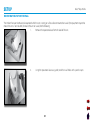
SETUP
Intelect® Transport Combo
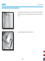
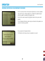
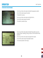
MOUNTING THE UNIT ON the WALL
The Intelect Transport Combo can be operated while the unit is resting on a flat surface or mounted on a wall (the equipment required to
mount the unit is not included). To mount the unit on a wall, do the following:
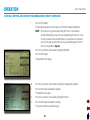
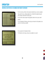
1.
Remove the repositional base from the back of the unit.
2.
Using the repositional base as a guide, mark the 4 wall holes with a pencil or pen.
31
SETUP
Intelect® Transport Combo
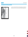
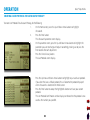
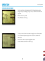
MOUNTING THE UNIT ON the WALL (continued)
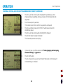
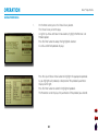
3.
Using an appropriate size drill bit, drill the four holes you marked in the previous step.
4.
Press 4 appropriately sized drywall anchors into the wall so that the drywall anchor is flush with the wall.
32
SETUP
Intelect® Transport Combo
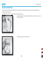
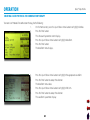
MOUNTING THE UNIT ON the WALL (continued)
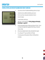
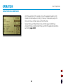
5.
Screw four #8 pan head sheet metal screws (1 inch or 2.54 cm) into the wall anchors. Make sure you leave ¼ of an inch (0.635 cm) between the wall and the head of the screw.
6.
Replace the repositional base on the back of the unit.
33
SETUP
Intelect® Transport Combo
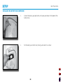
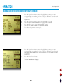
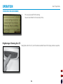
MOUNTING THE UNIT ON the WALL (continued)
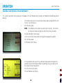
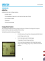
7.
Line up the screw heads with the holes on the repositional base, and slide the unit down slightly until the screw heads are securely fastened to the repositional base.
34
SETUP
Intelect® Transport Combo
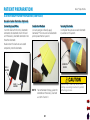
Installing the battery pack
The Intelect Transport Combo accommodates both AC mains power and an optional battery pack. The pack contains 20 Nickel Metal
Hydride (NiMH) drycell batteries.
To install the battery pack in the Intelect Transport Combo, do the following:
1.
Locate the battery access door at the bottom of the unit and loosen the screw with a flat head screwdriver.
2.
Remove the battery access door and retain it.
35
SETUP
Intelect® Transport Combo
Installing the battery pack (continued)
3.
Connect the battery pack cable to the unit’s battery connector in the bottom of the battery recess.
4.
Put the battery pack into the unit, making sure to orient it as shown.
36
SETUP
Intelect® Transport Combo
Installing the battery pack (continued)
5.
6.
Replace the battery access door and re-tighten the screw using the screwdriver.
Reverse the steps in this section in order to remove the battery pack.
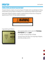
CHARGING THE BATTERY PACK
The battery pack is automatically charged by the unit whenever there is mains power connected. Charging may be interrupted during
operation of the unit by the control circuitry to limit total power consumption. A fully charged battery will provide 2-5 hours of treatment
depending on the applicator and the pulsed mode used.
NOTE: Even when the battery pack is connected, the unit will default to mains power when plugged in.
USING THE BATTERY PACK
To save battery power, the Intelect Transport Combo is equipped with a “power off” function. This function is activated when the unit is
powered on and has been left idle for approximately 5 minutes, at which time the unit powers off. To restore power, press the Power On/
Off button.
37
PATIENT PREPARATION
Intelect® Transport Combo
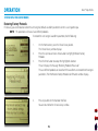
Electrotherapy Patient Preparation
Electrode Placement
Use the following guidelines when preparing patients for
electrotherapy:
•Examine the skin for any wounds and clean the skin.
•Apply the electrodes to the treatment area.
•Ensure the electrodes are applied securely to the skin.
•Ensure good contact between each electrode and the skin.
•Check the electrode contact regularly during the treatment.
•Examine the skin again after the treatment.
•Choose electrodes that fit the anatomy.
•Follow electrode manufacturer instructions.
• Keep electrodes separated during treatment. Electrodes in contact
with each other could result in improper stimulation or skin burns.
• Output current density is inversely related to electrode size (i.e.,
the larger the electrode, the lower the current density). Improper
application may result in patient injury. If any question arises as to
the proper electrode size, consult a licensed practitioner prior to
therapy session.
• Powered muscle stimulators should be used only with the leads and electrodes recommended for use by the manufacturer.
38
PATIENT PREPARATION
Intelect® Transport Combo
Electrotherapy Patient Preparation (continued)
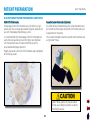
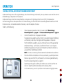
DURA-STICK Electrodes
Chattanooga DURA-STICK Electrodes are a self adhesive, single
patient, one time use disposable product designed specifically for
use with Chattanooga Electrotherapy systems.
It is recommended that Chattanooga DURA-STICK Electrodes be
used whenever possible to ensure the highest level of contact
with the treatment area and most uniform delivery of the
prescribed electrotherapy treatment.
Properly dispose of used DURA-STICK Electrodes upon completion
of the therapy session.
Reusable Carbon Electrodes (Optional)
If used for delivery of electrotherapy, the Carbon Electrodes must
be inserted into the sponges moistened with distilled water prior
to placement on the patient.
These Carbon Electrodes should be secured to the treatment area
using Nylatex® Wraps.
Nylatex® Wraps contain dry natural rubber
and may cause allergic reactions in patients
with allergies to latex.
39
PATIENT PREPARATION
Intelect® Transport Combo
Electrotherapy Patient Preparation (continued)
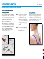
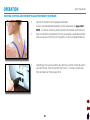
DURA-STICK Electrode Instructions
Connecting Lead Wires
Insert the lead with the Red (+) electrode
NOTE: Use of conductive medium or
connector into one DURA-STICK Electrode.
sponges is not required or
Insert the lead with the Black (-) electrode
recommended. DURA-STICK
connector into the other electrode.
Electrodes are manufactured to
ensure the optimum conductivity
Make certain the lead wires are
during therapy when properly
seated completely into the electrodes. Also,
applied.
ensure that the numbers on the electrodes
correspond to the appropriate color being
NOTE: For combination therapy, place
used (i.e., the black electrode labeled
the electrode on the black (-) lead
number 1 should be used with the red
and
use Stim Channel 1.
electrode labeled number 1).
LEAD WIRE seated
Red (+)
LEAD WIRE
Electrode
number
black (-)
LEAD WIRE
40
Securing Electrodes
Remove the DURA-STICK Electrodes from
the protective backing and apply to the
treatment area as prescribed. Ensure the
entire electrode surface is in contact with
patient skin by pressing into place.
PATIENT PREPARATION
Intelect® Transport Combo
Electrotherapy Patient Preparation (continued)
Reusable Carbon Electrodes (Optional)
Connecting Lead Wires
Insert the lead with the red (+) electrode
connector into electrode. Insert the lead
with the black (-) electrode connector into
the other electrode.
Conductive Medium
Use wet sponges or liberally apply
Conductor™ Transmission Gel to electrode
prior to placement on patient.
Securing Electrodes
Use Nylatex® Wrap to secure each electrode
in position on the patient.
Make certain the lead wires are seated
completely into the electrodes.
secure with
nylatex
RED (+)
LEAD WIRE
BLACK (-)
LEAD WIRE
NOTE: For combination therapy, place the
electrode on the black (-) lead and
use Stim Channel 1.
41
Nylatex® Wraps contain dry natural rubber
and may cause allergic reactions in patients
with allergies to latex.
PATIENT PREPARATION
Intelect® Transport Combo
Ultrasound Therapy Patient Preparation
Before applying the sound head to the patient, you must first prepare the patient’s skin for ultrasound therapy. By properly preparing the
patient’s skin for ultrasound therapy, you will allow more ultrasound energy to reach the targeted areas and reduce the risk of skin irritation.
To prepare the patient’s skin for ultrasound therapy, do the following:
1.
Thoroughly wash the skin on which you intend to place the sound head with mild soap and water.
2.
Dry the skin thoroughly.
3.
Apply the ultrasound gel generously to the target area on the patient.
NOTE: For combination therapy, place the electrode on the black (-) lead and use Stim Channel 1.
42
OPERATION
Intelect® Transport Combo
Starting, Stopping, and interrupting Electrotherapy
The Operator Interface consists of buttons with a liquid crystal display (LCD). The operator is able to view parameter options on the display
and make selections by pressing the buttons on the control panel. The LCD will provide continuous information during the treatments
concerning power and elapsed time. Parameters are adjusted using control panel buttons on the front of the unit. The output can be
stopped by pressing the “PAUSE” or “STOP” buttons located on the control panel.
Do not turn the unit on or off while it is connected to the patient.
To apply electrotherapy, do the following:
1.
Follow all appropriate procedures listed in the section entitled "Electrotherapy Patient Preparation" beginning on page 38.
2.
Turn system power “ON” by pressing the Power On/Off button.
The message "Initializing System" displays. The unit will go through self diagnostics, and the home screen displays on the LCD.
43
OPERATION
Intelect® Transport Combo
Starting, Stopping, and interrupting electrotherapy (continued)
3.
Connect the Lead Wires to the appropriate electrodes.
To see a list of recommended electrodes and their preparation, see pages 38-41.
NOTE: Do not use unnecessary force to connect the electrodes to the lead wires.
4.
Place the self adhesive electrodes on the sites prescribed by a qualified practitioner. Make sure you press them firmly on the patient’s skin to ensure good conductivity.
5.
Depending on the type of waveform you intend to use and the number of patients
you intend to treat, insert the Lead Wire into Channel 1, Channel 2, or both Lead Wire Connections on the Accessory Panel.
44
OPERATION
Intelect® Transport Combo
Starting, Stopping, and interrupting electrotherapy (continued)
6.
Use the Up and Down Arrow buttons to highlight either Stim Channel 1 or Stim
Channel 2.
7.
Press the Enter button.
The Waveform screen displays.
8.
Use the Up and Down Arrow buttons to highlight the appropriate waveform.
9.
Press the Enter button.
The Electrotherapy parameter screen displays.
45
OPERATION
Intelect® Transport Combo
Starting, Stopping, and interrupting electrotherapy (continued)
10.
Press the Up and Down Arrow buttons to highlight the parameter you want to change and adjust it accordingly, making sure to press the Enter button after each
adjustment.
11.
Press Enter to accept the parameters.
The Parameter screen refreshes and the new parameters are displayed.
12.
To begin therapy, press the START button.
The timer counts down, the output power ramps up, and "Running" displays below the timer.
NOTE: When the therapy time has expired, the unit beeps three times.
During therapy, you can press the TIME button to raise or lower treatment time (in one minute increments) using the up and down arrows.
During therapy, you can press the INTENSITY button to raise or lower the output using the up and down arrows.
Therapy can be interrupted at any time by pressing the STOP or PAUSE buttons.
When the STOP button is pressed, the unit stops emitting output, and the unit returns to the home screen. To resume therapy, repeat steps 6-11.
During treatment, the following occurs whenever the PAUSE button is pressed:
• the timer pauses
• the unit beeps quickly 5 times
• "Paused" displays below the timer
• the unit stops emitting output
To resume therapy, press the PAUSE button or the START button.
46
OPERATION
Intelect® Transport Combo
Starting, Stopping, and interrupting electrotherapy (continued)
13.
When you have completed treatment, remove all electrodes from the patient.
14.
Turn system power “OFF” by pressing the Power On/Off button.
The unit beeps once and the blue light on the Power On/Off button flashes intermittently.
47
OPERATION
Intelect® Transport Combo
Starting, Stopping, and interrupting Ultrasound therapy
To apply ultrasound therapy, do the following:
1.
Ensure the ultrasound applicator is plugged in.
2.
On the Home screen, use the Up and Down Arrow buttons to highlight
Ultrasound.
3.
Press the Enter button.
The Ultrasound parameters screen displays.
4.
Press the Up and Down Arrow buttons to highlight Frequency.
5.
Press the Enter button to select 1 or 3.3 MHz.
When the button is pressed, the frequency will toggle from 1 to 3.3 MHz and back
again as long as the button is being pressed (excluding the 1 cm2 sound head).
An audible tone will be heard when changes are made.
NOTE: With 2 cm2 and 5 cm2 sound heads, switching from 1 to 3.3 MHz
results in no change in power. When using a 10 cm2 head with greater
than 10 watts, changing from 1 to 3.3 MHz reduces power to 10 watts.
6.
Press the Up and Down Arrow buttons to highlight Duty Cycle.
7.
Press the Enter button to display the Duty Cycle menu.
8.
Press the Up and Down Arrow buttons to highlight 10%, 20%, 50% or Continuous
duty cycle.
When the buttons are pressed, an audible tone will be heard as the duty cycle
toggles through the options on the LCD.
9.
Press the Enter button to accept the selection.
48
OPERATION
Intelect® Transport Combo
Starting, Stopping, and interrupting ultrasound therapy (continued)
10.
11.
Press the Down Arrow button to highlight Display.
Press the Enter button to select either Watts or W/cm2.
When the button is pressed, the frequency will toggle from Watts to W/cm2 and back
again as long as the button is being pressed.
12.
Press the Down Arrow button to highlight Warming.
13.
Press the Enter button to select either On or Off.
When the button is pressed, the head warming feature will toggle from On to Off
and back again as long as the button is being pressed. When the head warming
feature is On, the sound head will warm to slightly above body temperature. The "Warming" message displays in the status window.
14.
Press the Down Arrow button to highlight Coupling.
15.
Press the Enter button to display the Coupling menu.
The coupling feature is designed to indicate when the sound head is not making adequate contact with the patient’s skin. “Good coupling” is achieved when the
appropriate amount of gel is used, and the sound head is making satisfactory contact
to the patient’s skin. Good coupling results in the most efficient use of ultrasound
therapy.
49
OPERATION
Intelect® Transport Combo
starting, Stopping, and interrupting ultrasound therapy (continued)
NOTE: The green light located on the back of the applicator flashes intermittently
when the sound head breaks contact with the patient.
Also, when the applicator becomes uncoupled, the message "Uncoupled"
displays in the status window.
Do not apply the Ultrasound Applicator to the patient during the Head
Warming period. Applicator must remain in Applicator Hook duing the
Head Warming period.
16.
Press the Up and Down Arrow buttons to select the manner in which you want to be
notified when the sound head becomes uncoupled.
The following list details these options:
• Pause timer & beep - the timer stops and the unit beeps once.
• Pause timer, no beep - the timer stops but the unit does not give an audible tone.
• Run timer & beep - the timer continues to count down and the unit beeps once.
• Run timer, no beep - the timer continues to count down, but the unit does not give
an audible tone.
NOTE: When the applicator becomes uncoupled during treatment, it continues to
distribute ultrasound energy.
17.
Press the Enter button to accept the selection.
50
OPERATION
Intelect® Transport Combo
starting, Stopping, and interrupting ultrasound therapy (continued)
18.
Press the Time button and raise or lower treatment time using the up and down
arrows.
19.
Press the INTENSITY button and raise or lower the unit’s output using the up and
down arrows.
20.
Press the Start button. The unit will beep 5 times and the ultrasound power will
distribute the selected output.
NOTE: When treatment time has expired a tone will sound three times.
21.
The therapy can be interrupted at any time by pressing the STOP or PAUSE buttons.
When the STOP button is pressed, the applicator stops emitting ultrasound energy,
and the unit returns to the default settings. To resume therapy, press the Start button.
When the PAUSE button is pressed, the timer pauses and the applicator stops emitting
ultrasound energy. To resume therapy, press the PAUSE button again.
22.
The parameters of the therapy can be changed at any time during the therapy session
by pressing the appropriate button.
23.
After therapy is complete, wipe excess ultrasound gel from the patient’s skin and the
sound head.
51
OPERATION
Intelect® Transport Combo
starting, Stopping, and interrupting combination therapy
Combination therapy consists of using electrotherapy and ultrasound therapy simultaneously. You may choose to use one or both channels
of electrotherapy in conjunction with ultrasound.
Combination therapy utilizes the ultrasound modality in conjuction with High Voltage Pulsed Current (HVPC), Premodulated, or
Interferential to generate a therapeutic effect. In this mode of therapy, the sound head of the ultrasound applicator becomes one half of
the electrical circuit. An electrode attached to the black (-) Lead Wire completes the circuit.
To do this, do the following:
1.
Follow all appropriate procedures listed in the section entitled "Electrotherapy
Patient Preparation" on page 38 and "Ultrasound Patient Preparation" on page 42.
2.
Connect the Lead Wires to the appropriate electrodes.
For example, for all waveforms used by Channel 1 (all waveforms except Interferential),
use the black (-) Lead Wire as the negative and the applicator as the positive.
For the Interferential waveform, you will use three lead wires and the applicator for
combination therapy: use the black (-) Lead Wire for Channel 1 as the negative
electrode, the applicator as the positive, and the other Lead Wires for channel 2 as
you would for an electrotherapy treatment.
NOTE: Do not use unnecessary force to connect the electrodes to the Lead Wires.
3.
Place the self adhesive electrodes on the sites prescribed by a qualified practitioner. Make sure you press them firmly on the patient’s skin to ensure good conductivity.
4.
Ensure the ultrasound applicator is plugged in.
5.
Depending on the type of waveform you intend to use, insert the Lead Wire into
Channel 1 or both Lead Wire Connections on the Accessory Panel.
6.
On the Home screen, press the Up and Down Arrow buttons to highlight Combo.
52
OPERATION
Intelect® Transport Combo
starting, Stopping, and interrupting combination therapy (continued)
7.
Press the Enter button.
The Ultrasound parameters screen displays with the Edit Stim option highlighted.
NOTE: When you are using combination therapy for Channel 1 (all waveforms except Interferential), you may only set up electrotherapy for Channel 1. If you
want to use both channels of electrotherapy in conjunction with ultrasound,
you must first begin treatment. You may set up electrotherapy for Channel 2
later in these procedures (step 21).
8.
Press the Up and Down Arrow buttons to highlight Waveform.
9.
Press the Enter button.
The Waveform menu displays.
10.
Press the Up and Down Arrow buttons to highlight the appropriate waveform.
11.
Press the Enter button to accept the selection.
The Waveform menu closes.
12.
Press the Up and Down Arrow buttons to highlight Edit Stim.
13.
Press the Enter button to accept the selection.
The current waveform's parameters display.
53
OPERATION
Intelect® Transport Combo
starting, Stopping, and interrupting combination therapy (continued)
14.
Press the Up and Down Arrow buttons to highlight the parameter you want to change and adjust it accordingly, making sure to press the Enter button after each adjustment.
15.
Press Enter to accept the parameters.
The Parameter screen refreshes and the new parameters are displayed.
16.
Press the up and down arrows on the INTENSITY button to raise or lower the electrotherapy output.
17.
Press the Up and Down Arrow buttons to highlight Edit Ultrasound.
18.
Press the Enter button to accept the selection.
The Ultrasound parameter screen displays.
19.
Continue with steps 4-23 of the section entitled "Starting Stopping and Interrupting Ultrasound Therapy" on pages 48-51.
20.
Press the START button.
The unit will beep 5 times, you are returned to the Home screen, and the ultrasound and electrotherapy is distributed.
54
OPERATION
Intelect® Transport Combo
starting, Stopping, and interrupting combination therapy (continued)
21.
If you want to use Channel 2 for additional electrotherapy, continue with step 22.
If you do not want to use additional electrotherapy, skip to step 25.
22.
Press the Up and Down Arrow buttons to highlight Stim Channel 2.
23.
Press the Enter button.
The Select Waveform screen displays.
24.
Follow steps 8-12 of the section entitled "Starting, Stopping, and Interrupting Electrotherapy" on pages 43-47.
25.
You may make parameter changes and stop or pause therapy on Channel 1, Channel
2, or Ultrasound by highlighting the appropriate form of therapy, and making the necessary changes.
26.
When you have completed treatment, remove all electrodes from the patient.
27.
Turn system power “OFF” by pressing the Power On/Off button.
The unit beeps once and the blue light on the Power On/Off button flashes intermittently.
55
OPERATION
Intelect® Transport Combo
Creating a user protocol for electrotherapy
This is a library you create. You may store up to 15 protocols in the User Protocol Library. To create User Protocols for electrotherapy, do the
following:
1.
On the home screen, press the Up and Down Arrow buttons to highlight either Stim
Channel 1 or Stim Channel 2.
2.
Press the Enter button.
NOTE: User protocols can be used on any channel (Stim Channel 1, Stim Channel
or Ultrasound). It does not matter on which channel they are created.
The Select Waveform screen displays.
3.
Use the Up and Down Arrow buttons to highlight the appropriate waveform.
4.
Press the Enter button.
The Parameter screen displays.
5.
On the parameter screen, press the Up and Down Arrow buttons to highlight the parameter you want to change and adjust it accordingly, making sure to press the Enter button after each adjustment.
6.
Press the Clinical Library button.
The Save Protocol screen displays.
56
OPERATION
Intelect® Transport Combo
Creating a user protocol for electrotherapy (continued)
7.
Press the Up Arrow and Down Arrow buttons to highlight any unused user protocol.
If you select the Save as Default protocol, this will become the protocol displayed when the waveform is selected on the Waveform screen.
8.
Press the Enter button to accept the highlighted selection and save your custom protocol.
The User Protocol Confirmation window displays to indicate that the protocol is now saved as the number you specified.
9.
Press any button on the Operator Interface.
The Parameter screen displays and your new protocol is now saved.
57
OPERATION
Intelect® Transport Combo
Creating a user protocol for ultrasound therapy
To create User Protocols for ultrasound therapy, do the following:
1.
On the Home screen, press the Up and Down Arrow buttons to highlight
Ultrasound.
2.
Press the Enter button.
The Ultrasound parameter screen displays.
3.
On the parameter screen, press the Up and Down Arrow buttons to highlight the parameter you want to change and adjust it accordingly, making sure to press the Enter button after each adjustment.
4.
Press the Clinical Library button.
The Save Protocol screen displays.
5.
Press the Up Arrow and Down Arrow buttons to highlight any unused user protocol.
If you select the Save as Default protocol, this will become the protocol displayed when Ultrasound is selected on the Home screen.
6.
Press the Enter button to accept the highlighted selection and save your custom protocol.
The User Protocol Confirmation window displays to indicate that the protocol is now saved as the number you specified.
58
OPERATION
Intelect® Transport Combo
Creating a user protocol for ultrasound therapy (continued)
7.
Press any button on the Operator Interface.
The Parameter screen displays and your new protocol is now saved.
59
OPERATION
Intelect® Transport Combo
Creating a user protocol for combination therapy
To create User Protocols for combination therapy, do the following:
1.
On the Home screen, press the Up and Down Arrow buttons to highlight Combo.
2.
Press the Enter button.
The Ultrasound parameter screen displays.
3.
Press the Up and Down Arrow buttons to highlight Waveform.
4.
Press the Enter button.
The Waveform menu displays.
5.
Press the Up and Down Arrow buttons to highlight the appropriate waveform.
6.
Press the Enter button to accept the selection.
The Waveform menu closes.
7.
Press the Up and Down Arrow buttons to highlight Edit Stim.
8.
Press the Enter button to accept the selection.
The waveform's parameters display.
60
OPERATION
Intelect® Transport Combo
creating a user protocol for combination therapy (continued)
9.
Press the Up and Down Arrow buttons to highlight the parameter you want to change and adjust it accordingly, making sure to press the Enter button after each adjustment.
10.
Press the Up and Down Arrow buttons to highlight Edit Ultrasound.
11.
Press the Enter button to accept the highlighted selection.
The Ultrasound parameter screen displays.
12.
Press the Up and Down Arrow buttons to highlight the parameter you want to
change and adjust it accordingly, making sure to press the Enter button after each
adjustment.
13.
Press the Clinical Library button.
The Save Protocol screen displays.
61
OPERATION
Intelect® Transport Combo
creating a user protocol for combination therapy (continued)
14.
Press the Up Arrow and Down Arrow buttons to highlight any unused user protocol.
If you select the Save as Default protocol, this will become the protocol displayed when Combo is selected on the Home screen.
15.
Press the Enter button to accept the highlighted selection and save your custom protocol.
The User Protocol Confirmation window displays to indicate that the protocol is now saved as the number you specified.
16.
Press any button on the Operator Interface.
The Parameter screen displays and your new protocol is now saved.
62
OPERATION
Intelect® Transport Combo
Using Protocols
1.
On the home screen, press the Clinical Library button.
The Clinical Library screen displays.
2.
Using the Up Arrow and Down Arrow buttons, highlight the Retrieve User Protocol option.
3.
Press the Enter button to accept the highlighted selection.
A list of user-defined protocols displays.
4.
Press the Up and Down Arrow button to highlight the appropriate protocol.
As you highlight each protocol, a description of the protocol’s parameters
displays to the right.
5.
Press the Enter button to select the highlighted protocol.
The Parameters screen displays the parameters of the protocol you selected.
63
OPERATION
Intelect® Transport Combo
Using Protocols (continued)
6.
Verify the parameters of this program, and use the appropriate buttons on the Operator Interface to adjust any setting, if necessary. For example, to adjust the time, press the up and down arrows on the TIME button.
7.
To begin therapy, and depending on if you intend to apply electrotherapy,
ultrasound therapy, or combination therapy, perform the appropriate procedures
outlined on pages 38-55.
64
OPERATION
Intelect® Transport Combo
SYSTEM UTILITIES
Audible Tones
Audible tones will be heard in the following conditions:
• Any button is pressed.
• The rechargeable battery’s power is low (in which case the Low Battery icon will display).
• Any error message is displayed.
• Therapy begins.
• The therapy time reaches 0:00.
Changing Protocol Parameters
You may change any parameter prior to or during therapy. To make Intensity and Treatment Time changes, touch the respective buttons and use the up or down arrows to advance to the desired settings.
To change other parameters during therapy, do the following:
1.
On the home screen, use the Up and Down Arrow buttons to highlight the channel on which therapy is currently running.
2.
Press the Enter button to select the highlighted option.
The parameters of the current therapy session display.
3.
Press the Up and Down Arrow buttons to highlight the parameter you want to change and adjust it accordingly, making sure to press the Enter button after each adjustment.
65
OPERATION
Intelect® Transport Combo
System UTILITIES (continued)
Changing Default Protocols for Electrotherapy
To change the power up presets, do the following:
1.
On the home screen, press the Up and Down Arrow buttons to highlight either Stim Channel 1 or Stim Channel 2.
2.
Press the Enter button to select the highlighted option.
The Select Waveform screen displays.
3.
Use the Up and Down Arrow buttons to highlight the appropriate waveform.
4.
Press the Enter button.
The parameter screen displays.
5.
Press the Up and Down Arrow buttons to highlight the parameter you want to change and adjust it accordingly, making sure to press the Enter button after each adjustment.
6.
Press the Clinical Library button.
The Save Protocol screen displays.
66
OPERATION
Intelect® Transport Combo
System UTILITIES (continued)
7.
Use the Up Arrow and Down Arrow buttons to highlight Save as Default protocol.
This will become the protocol displayed when the waveform is selected on the Waveform screen.
8.
Press the Enter button to accept the highlighted selection.
The Default Protocol Confirmation window displays.
9.
Press any key to confirm the settings.
You are returned to the Clinical Library menu.
67
OPERATION
Intelect® Transport Combo
System UTILITIES (continued)
Changing Default Protocols for Ultrasound Therapy
1.
On the home screen, press the Up and Down Arrow buttons to highlight Ultrasound.
2.
Press the Enter button to select the highlighted option.
The Ultrasound parameters screen displays.
3.
Press the Up and Down Arrow buttons to highlight the parameter you want to change and adjust it accordingly, making sure to press the Enter button after each adjustment.
4.
Press the Clinical Library button.
The Save Protocol screen displays.
5.
Use the Up Arrow and Down Arrow buttons to highlight Save as Default protocol.
This will become the protocol displayed when Ultrasound is selected on the Home screen.
6.
Press the Enter button to accept the highlighted selection.
The Default Protocol Confirmation window displays.
68
OPERATION
Intelect® Transport Combo
System UTILITIES (continued)
7.
Press any key to confirm the settings.
You are returned to the Clinical Library menu.
Changing Default Protocols for Combination Therapy
1.
On the home screen, press the Up and Down Arrow buttons to highlight Combo.
2.
Press the Enter button to select the highlighted option.
The Ultrasound parameters screen displays.
3.
Press the Up and Down Arrow buttons to highlight Waveform.
4.
Press the Enter button.
The Waveform menu displays.
69
OPERATION
Intelect® Transport Combo
System UTILITIES (continued)
5.
Press the Up and Down Arrow buttons to highlight the appropriate waveform.
6.
Press the Enter button to accept the selection.
The Waveform menu closes.
7.
Press the Up and Down Arrow buttons to highlight Edit Stim.
8.
Press the Enter button to accept the selection.
The waveform's parameters display.
9.
Press the Up and Down Arrow buttons to highlight the parameter you want to change and adjust it accordingly, making sure to press the Enter button after each adjustment.
10.
Press the Up and Down Arrow buttons to highlight Edit Ultrasound.
11.
Press the Enter button to accept the highlighted selection.
The Ultrasound parameter screen displays.
70
OPERATION
Intelect® Transport Combo
System UTILITIES (continued)
12.
Press the Up and Down Arrow buttons to highlight the parameter you want to change and adjust it accordingly, making sure to press the Enter button after each adjustment.
13.
Press the Clinical Library button.
The Save Protocol screen displays.
14.
Use the Up Arrow and Down Arrow buttons to highlight Save as Default protocol.
This will become the protocol displayed when Ultrasound is selected on the Home screen.
15.
Press the Enter button to accept the highlighted selection.
The Default Protocol Confirmation window displays.
71
OPERATION
Intelect® Transport Combo
System UTILITIES (continued)
16.
Brightening or Dimming the LCD
Press any key to confirm the settings.
You are returned to the Clinical Library menu.
To brighten or dim the LCD, turn the contrast control dial until the display contrast is optimal.
72
OPERATION
Intelect® Transport Combo
System UTILITIES (continued)
Restoring Factory Protocols
If necessary, you can choose to restore the unit’s original (default) waveform parameters when it was shipped to you.
NOTE: This procedure will erase all user-defined protocols.
To restore the unit’s original waveform parameters, do the following:
1.
On the Home screen, press the Clinical Library button.
The Clinical Library window displays.
2.
Press the Up Arrow or Down Arrow buttons to highlight Restore Factory Protocols.
3.
Press the Enter button to accept the highlighted selection.
The unit displays the message "Restoring Protocols Please wait."
The user-defined protocols are erased and the waveforms are restored to the original parameters. Then the Restore Factory Protocols Confirmation window displays.
4.
Press any button on the Operator Interface.
You are returned to the Clinical Library window.
73
OPERATION
Intelect® Transport Combo
System UTILITIES (continued)
Changing Languages
You may change the language displayed by the Intelect Transport Combo to the following:
• English
• Spanish
To change the language displayed on the LCD, do the following:
1.
Press the Clinical Library button.
The Clinical Library screen displays.
2.
Use the Down Arrow and Up Arrow buttons to highlight the Language option.
3.
Press the Enter button to accept the highlighted selection.
The Language menu displays.
4.
Press the Up and Down Arrow buttons to highlight the appropriate language.
74
OPERATION
Intelect® Transport Combo
System UTILITIES (continued)
5.
Press the Enter button to accept the highlighted selection.
The unit now displays the language you selected.
Restoring Factory Settings
To restore the original language on the unit, do the following:
1.
On the Home screen, press the Clinical Library button.
The Clinical Library screen displays.
2.
Press the Up Arrow or Down Arrow buttons to highlight the Restore Factory Setting
option.
3.
Press the Enter button to accept the highlighted selection.
The Restore Factory Settings Confirmation screen displays.
75
OPERATION
Intelect® Transport Combo
system UTILITIES (continued)
4.
Press any button on the Operator Interface.
The default power up settings are restored and you are returned to the Clinical Library screen.
Viewing Unit Version Information
Use this utility to determine the unit’s software version. To do this, do the following:
1.
On the Home screen, press the Clinical Library button.
The Clinical Library screen displays.
2.
Use the Up Arrow and Down Arrow buttons to highlight the View Unit Information option.
3.
Press the Enter button to accept the highlighted selection.
The Unit Version Information screen displays.
76
OPERATION
Intelect® Transport Combo
System UTILITIES (continued)
4.
Press any key to return to the Clinical Library window.
77
TROUBLESHOOTING
Intelect® Transport Combo
Error codes
The Intelect Transport Combo displays error messages to inform the user of problems or potential problems with the unit, modality, or
accessories. These are numbered so the user can possibly correct the problem without the aid of service personnel. Use the following
Troubleshooting Charts to define the error codes, and locate the probable cause and possible remedies before contacting the dealer or
factory for technical service.
Code
Number
Type Message
Probable Cause
Possible Remedies
104
Message
User attempted to perform an electrotherapy session, but both
channels are already in use.
A. Wait until the previous therapy session finishes.
B. Press the STOP button to end the therapy session on either channel.
105
Message
User selected a two channel electrotherapy treatment, but at least
one channel is already in use.
A. Wait until the previous therapy session finishes.
B. Press the STOP button to end the therapy session on either channel.
106
Warning
Overcurrent
A. Check Electrodes and Lead Wires. Make certain Lead Wires are not damaged and are properly
connected to the system. Make certain Lead Wires are properly connected to the Electrodes
and that electrodes are not damaged and are making proper contact with treatment area.
B. Replace Lead Wires and Electrodes.
107
Warning
Bad Contact Quality
A. Make certain Electrodes are making proper contact with the treatment area.
B. Make certain Lead Wires are properly connected to Electrodes.
C. Replace Electrodes and Lead Wires.
108
Warning
Shorted Lead Wires
A. Check Electrodes and Lead Wires. Make certain Lead Wires are not damaged and are properly
connected to the system. Make certain Lead Wires are properly connected to the Electrodes
and that electrodes are not damaged and are making proper contact with treatment area.
B. Replace Lead Wires and Electrodes.
109
Message
While performing ultrasound therapy using the 10 cm2 sound at
an intensity greater than 15 W (1.7 W/cm2), user attempted to
begin an electrotherapy session on a second channel.
A. Use a smaller sound head.
B. Set the ultrasound at an intensity less than 15 W (1.7 W/cm2).
C. Wait until ultrasound session is complete.
200-399
Message
Refer to Warning on next page.
Refer to Warning on next page.
78
TROUBLESHOOTING
Intelect® Transport Combo
Error codes (continued)
In the event that an Error message or Warning appears beginning with
a 2 or 3, immediately stop all use of the unit and contact the dealer or
DJO, LLC for service. Errors and Warnings in these categories indicate an
internal problem with the unit that must be tested by DJO, LLC or a Field
Service Technician certified by DJO, LLC before any further operation or
use of the system.
Use of a unit that indicates an Error or Warning in these categories may
pose a risk of injury to the patient, user, or extensive internal damage to
the system.
79
TROUBLESHOOTING
Intelect® Transport Combo
troubleshooting the display and error messages
Troubleshooting the Display
If you press the Power On/Off button, and the LCD remains blank longer than a few seconds,
the contrast may require adjusting. To adjust it, turn the contrast control dial clockwise until the
display contrast is optimal.
Troubleshooting Error Messages
The following messages are displayed on the LCD under the following conditions:
MessageDisplayed When
Over Temp
sound head reaches a temperature which could damage the crystal
Unplugged
sound head not plugged in or faulty sound head
Uncoupled
sound head is not making good contact with the patient
80
ACCESSORIES
Intelect® Transport Combo
Standard Accessories
Ref.
28098
Optional Accessories
Description
Electrotherapy Accessory Kit- Includes the following:
Qty
Ref.
1
27381
27382
27384
27478
2884
27467
1 cm2 Applicator (Gray) [26 AWG, 68.89 in (174.143 cm), Shielded]
2 cm2 Applicator (Gray) [26 AWG, 68.89 in (174.143 cm), Shielded]
10 cm2 Applicator (Gray) [26 AWG, 68.89 in (174.143 cm), Shielded]
NiMH Battery Pack
Cart Adapter
Intelect Transport Carrying Bag
10648
Nylatex® Wrap (2 per pack)
72852
3" (8 cm) Black Rubber Carbon Electrodes (2 per pack)
72853
3" (8 cm) Red Rubber Carbon Electrodes (2 per pack)
27312
Channel 1 Lead Wire [16/18 AWG, 98.43 in (250.012 cm), Unshielded]
1
27313
Channel 2 Lead Wire [16/18 AWG, 98.43 in (250.012 cm), Unshielded]
1
42044
2.75 in (7 cm) Round Disposable Electrodes (4 per pack)
1
27325
Mains Power Cord
1
27383
5 cm2 Applicator (Gray) [26 AWG, 68.89 in (174.143 cm), Shielded]
1
4248
Ultrasound Transmission Gel 9 oz (255 g) bottle
1
28156
User Manual
1
81
Description
MAINTENANCE
Intelect® Transport Combo
Maintaining THE UNIT
Cleaning the Unit and the Accessories
With the unit disconnected from the power source, clean the unit with a clean, lint free cloth moistened with water and mild antibacterial
soap. If a more sterile cleaning is needed, use a cloth moistened with an antimicrobial cleaner.
Do not submerge the unit in liquids. Should the unit accidentally become wet, contact the dealer or DJO, LLC Service Department
immediately. Do not attempt to use a unit that has been wet inside until inspected and tested by a Service Technician Certified by DJO, LLC.
To clean the Lead Wires, disconnect them from the unit and wipe down with a clean, lint free cloth moistened with water and mild
antibacterial soap.
To clean the optional reusable carbon electrodes, remove them from the Lead Wires and wipe down with isopropyl alcohol. Repeat this
procedure for the sponges as well.
The following items should be checked at least monthly to ensure proper operation of this unit:
• Power cord and plug: Check to make sure the cord is not frayed, kinked, and does not have torn or cut insulation.
• Applicator cable: Check to make sure the cable is flexible, free of kinks, not frayed, and the insulation is intact.
• Sound head face: Check to see that there is no build-up of gel or foreign material on the aluminum face.
NOTE:
The sound head must be cleaned with alcohol between each therapy session. The aluminum surface
may be disinfected with alcohol, but avoid the plastic area.
NOTE: The unit must be recalibrated annually. The unit was calibrated during the manufacturing process and
is ready to be placed into service upon delivery.
82
MAINTENANCE
Intelect® Transport Combo
factory service
When the Intelect Transport Combo requires factory service, contact the selling dealer or DJO, LLC Service Department. All units returned to the
factory for service must include the following:
WARRANTY REPAIR/OUT OF WARRANTY REPAIR
1. Written statement containing the following information:
• RA (Return Authorization) Number- Obtain from Factory
• Model Number
• Serial Number
• Contact Person with Phone and Fax Numbers
• Billing Address (for Out of Warranty Repair)
• Shipping Address (Where to Ship Unit after Repair)
• Detailed Description of Problem or Symptoms
2. Copy of original invoice issued at purchase.
3. Ship the unit to address specified by an authorized service technician.
EU Directive on Waste Electrical
and Electronic Equipment
(WEEE) ensures that product
is appropriately disposed of or
recycled at the end of its life.
Service to these units should be performed only by Service Technicians certified by DJO, LLC.
83
WARRANTY
Intelect® Transport Combo
DJO, LLC, ("Company"), warrants that the Intelect Transport Combo ("Product") is free of defects in material and workmanship. This warranty shall remain in effect for two years
(24 months) from the date of original consumer purchase. If this Product fails to function during the two year warranty period due to a defect in material or workmanship, at
the Company's option, the Company or the selling dealer will repair or replace this Product without charge within a period of thirty days from the date on which the Product
is returned to the Company or the dealer.
All repairs to the Product must be performed by a service center certified by the Company. Any modifications or repairs performed by unauthorized centers or groups will
void this warranty.
The warranty period for accessories is 90 days. Accessories include Lead Wires, Electrodes, and Nylatex®.
The warranty period for applicators is one year (12 months).
This warranty does not cover:
Replacement parts or labor furnished by anyone other than the Company, the selling dealer, or a service technician certified by the Company.
Defects or damage caused by labor furnished by someone other than Company, the selling dealer, or a certified Company service technician.
Any malfunction or failure in the Product caused by product misuse, including, but not limited to, the failure to provide reasonable and required maintenance or any use that
is inconsistent with the Product User's Manual.
COMPANY SHALL NOT BE LIABLE IN ANY EVENT FOR INCIDENTAL OR CONSEQUENTIAL DAMAGES.
Some locations do not allow the exclusion or limitation of incidental or consequential damages, so the above limitation or exclusion may not apply to you.
To obtain service from Company or the selling dealer under this warranty:
1. A written claim must be made within the warranty period to the Company or the selling dealer. Written claims made to the Company should be sent to:
DJO, LLC
1430 Decision St
Vista, CA 92081 USA
T: 1-800-592-7329 USA
T: 1-317-406-2209
F: 1-317-406-2014
and
2. The Product must be returned to the Company or the selling dealer by the owner.
This warranty gives you specific legal rights and you may also have other rights which vary from location to location.
The Company does not authorize any person or representative to create for it any other obligation or liability in connection with the sale of the Product.
Any representation or agreement not contained in the warranty shall be void and of no effect.
THE FOREGOING WARRANTY IS IN LIEU OF ALL OTHER WARRANTIES, EXPRESSED OR IMPLIED,
INCLUDING ANY WARRANTY OR MERCHANTABILITY OR FITNESS FOR A PARTICULAR PURPOSE.
84
Moving
Rehabilitation
Forward™
ISO 13485 Certified
DJO, LLC
1430 Decision St
Vista, CA 92081 USA
T: 1-800-592-7329 USA
T: + 1-317-406-2209
F: + 1-317-406-2014
chattgroup.com
© 2010 DJO, LLC
28384_C