1
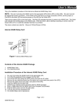
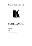
Your Component/RGB/YC/CV/XGA Transmitter and Receiver
4
Your Component/RGB/YC/CV/XGA Transmitter and Receiver
This section describes:
Your WPN-11 (see section 4.1)
Your WPN-12 (see section 4.2)
Your BC-5X5S Cable (optional) PINOUT (see section 4.3)
4.1 Your WPN-11
Figure 1 and Table 1 define the WPN-11:
Figure 1: WPN-11 (Front Panel, Side Panel, and 3-D Illustration)
Table 1: WPN-11 Features
#
1
2
3
4
Feature
Holes (2)
XGA INPUT HD15 Connector
ON LED
SELECT (COMP/CV/YC or
XGA) Button
5 B/B-Y/Y(YC) IN RCA Connector
6 G/Y/CV IN RCA Connector
7 R/R-Y/C(YC) IN RCA Connector
8 OUTPUT TO LINE Terminal
Block Connectors
9 GND PIN
10 +12VDC IN PIN
Function
For fastening the wall plate in place
Connects to the computer graphics source
Illuminates when receiving power
Push in to select XGA; release to select component video/RGB1,
or composite video, or s-Video
Connects to the RGB/component video/s-Video2 source
Connects to the RGB/component video/composite video source
Connects to the RGB/component video/s-Video2 source
Connects to the corresponding INPUT FROM LINE terminal block
connectors using the optional BC-5X5S cable (see section 4.3)
Connects (-) to the Ground
Connects (+) to the connector for powering the unit
1 With sync on green
2 Made up of the Y on the B/B-Y/Y(YC) connector together with the C on the R/R-Y/C(YC) connector
3