1
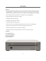
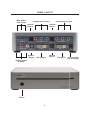
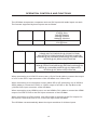
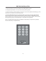
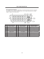
HD Mate Scaler
USER
MANUAL
www.gefen.com
ASKING FOR ASSISTANCE
Technical Support:
Telephone
(818) 772-9100
(800) 545-6900
Fax
(818) 772-9120
Technical Support Hours:
8:00 AM to 5:00 PM Monday through Friday PST
Write To:
Gefen Inc.
c/o Customer Service
20600 Nordhoff St
Chatsworth CA 91311
www.gefen.com
[email protected]
Notice
Gefen Inc. reserves the right to make changes in the hardware, packaging and any
accompanying documentation without prior written notice.
The HD Mate Scaler is a trademark of Gefen Inc.
© 2007 Gefen Inc., All Rights Reserved
TABLE OF CONTENTS
1
Introduction / Operation Notes
2
Features
3
Panel Layout
4
Operation Controls and Functions
5
Operation Controls and Functions
6
Operation Controls and Functions / Color Settings
7
Output Settings / OSD Adjustment / Information
8
Using the HD Mate Scaler
9
RMT-SR-IR Installation
10
Pin Configuration
11
Specifications
12
Terminology
13
Warranty
INTRODUCTION
Thank you for purchasing the HD Mate Scaler.
The HD Mate Scaler switches two Component sources and one DVI source, all with digital
TOSlink and analog audio inputs.
The Gefen HD Mate Scaler allows you to upscale and switch your standard definition or
high definition component sources to resolutions up to 1080p. Anything from set-top boxes,
DVD players to the next generation of gaming consoles including the Xbox 360 and PS3
can be plugged into the HD Mate Scaler.
Note: The switching is done by using the RMT-SR-IR remote control. Any HDTV with
HDMI inputs can be connected to the DVI output of the HD Mate by using a DVI to HDMI
adapter, if the cable being used is HDMI.
OPERATION NOTES
READ THESE NOTES BEFORE INSTALLING
OR OPERATING THE HD MATE
• The HD Mate works with all DVI and HDMI displays.
• The HD Mate is not HDCP compliant.
1
FEATURES
Features
• Both digital and analog inputs are format converted and pixel re-scaled through the
HD Mate Scaler. It outputs a large range of formats and resolutions that will easily
match the native resolution/ format of your display to ensure highest picture quality.
• DVI compliant input: Operates up to 165Mhz (Up to UXGA @60Hz)
• Supports digital HD output up to 1080p.
• Integrated 8-bit triple-ADC/PLL.
• Integrated DVIcompliant receiver.
• Dual high quality scaling engines.
• Dual 3-D motion video adaptive de-interlacers with smooth low-angle edge.
• Automatic 3:2 pull-down & 2:2 pull-down detection and recovery.
• High performance frame rate conversion engine.
• Operates through on-screen OSD menu control and remote control.
Includes:
(1) HD Mate Scaler
(1) 6 ft DVI cable (M-M)
(1) 5V Power Supply
(1) IR Remote control
(1) User’s Manual
2
PANEL LAYOUT
Mini Audio
Jack Inputs
Component 1 Input
Component 2 Input
Optical
Input 1
Optical
Input 2
Optical
Output
DVI Output
Analog Audio
Outputs
IR Eye
3
Optical
Input 3
DVI Input
Connects 5V
Power Supply
OPERATION CONTROLS AND FUNCTIONS
The HD Mate accepts two component and one DVI inputs with audio inputs on each.
The formats supported by these inputs are as follows:
COMPONENT
YPbPr
480p @ 50/60Hz
576p @ 50Hz
720p @ 50/60Hz
1080i @ 50/60Hz
1080p @ 50//60Hz
480i @ 60Hz
576i @ 50Hz
YCbCr
PC INPUT:
RGBHV
VGA/SVGA/XGA/SXGA/UXGA/WXGA/WSXGA/WUXGA
VGA@ (60//72/75/85/SVGA @ (56/60/72/75/85)
XGA @ (60/70/75/85)/SXGA @ (60/75/85)/UXGA @
60/WXGA @ 60(1280x800)/WSXGA @ 60(1680x1050)/
WUXGA @ 60(1920x1200)/1360x768
DVI INPUT:
Digital
VGA @ (60/72/75/85)/SVGA @ (56/60/72/75/85)/
XGA @ (60/70/75/85)/SXGA @ (60/75/85)/UXGA @ 60/
WXGA @ (1280x800)/WSXGA @ 60(1680x1050)/
WUXGA @ 60(1920x1200)/1360x768
When connecting to a VGA PC source use a 15-pin D-sub cable to connect the output
of a PC to the DVI-I input connector of the HD Mate via a VGA to DVI.
When connecting to a component source (either SD or HD resolution) use a 3RCA to
3RCA cable to connect the YPbPr or YCbCr output of a DVD or Set Top Box to the
y-Cb/Pb-Cr/Pr input connector of the HD Mate.
When connecting to an HDMI source, use an HDMI to DVI cable to connect the HDMI
output of a STB or DVD to the DVI input connector of the HD Mate.
When connecting to a DVI source, use a DVI cable to connect to the DVI output of a
DVI source, such as a DVD or PC, to the DVI input of the HD Mate.
The HD Mate can automatically detect the input resolution of all three inputs.
4
OPERATION CONTROLS AND FUNCTIONS
After you power on the unit, press the menu button and it will bring up the main menu
as follows:
Video (or PC): When Video is selected, a sub menu as shown below, will come up.
5
OPERATION CONTROLS AND FUNCTIONS
Picture mode: There are four picture modes for customers to choose from.
User: Select to adjust to your favorite setting and store it.
Standard: Standard factory default setting for optimal display in a normal
environment.
Vivid: High saturation picture for optimal display in a bright room.
Movie: Picture for comfortable low brightness display in a dark room.
Scale: Select overscan when input source is SD or HD video to ensure there will be no
black band around the screen border. Select underscan when input source is PC signal
to ensure full picture content will fall within the screen border.
Noise Reduction (NR): This function only works when the input source is analog RGB
or component, It will not work for the DVI input. There are four settings for Noise
Reduction-Off, Low, Middle, and High. The Noise Reduction will remove the noise that
results from the analog to digital conversion and digital scaling process.
H & V position: Adjust for the best horizontal and vertical position of the picture on the
screen.
COLOR SETTINGS
User: Select to adjust to your favorite color temperature setting.
Normal: Normal color tone setting where white is pure white.
Warm: Warm color tone makes white a little reddish.
Cool: Cool color tone makes white a little bluish.
Value of normal setting
6
OUTPUT SETTINGS
Output: The HD Mate can output a wide variety of PC and HD resolutions as
follows.
VGA (up to 100MH) DVI/HDMI (up to 165 MH)
480i
480i
480p
480p
576i
576i
576p
576p
720p @ (50/60)
720p @ (50/60)
1080i @ (25/30)
1080i @ (25/30)
1080p @ (50/60)
1080p @ (50/60)
VGA @ 60
VGA @ 60
SVGA @ 60
SVGA @ 60
XGA @ 60
XGA @ 60
SXGA @ 60
SXGA @ 60
UXGA
UXGA
WXGA @ 60
WXGA @ 60
WSXGA @ 60
WSXGA @ 60
WUXGA @ 60
WUXGA @ 60
Resolution
720x480
720x480
720x576
720x576
1280x720
1920x1080
1920x1080
640x480
800x600
1024x768
1280x1024
1600x1200
1280x800
1680x1050
1920x1200
i/p*
i
p
i
p
p
i
p
p
p
p
p
p
p
p
p
* i: interlaced p; progressive
Native: When selected, the HD Mate will automatically adjust its output
timing to match the native timing of the display.
OSD ADJUSTMENT
H. Position: Adjust the horizontal position of the OSD graphic.
V. Position: Adjust the vertical position of the OSD graphic.
Time out: Set a pre-determined Time to turn off OSD menu on the screen.
Background: To select transparent or solid background of OSD graphic.
INFORMATION
Project: Show product model number.
Input: Show input resolution i.e. XGA.
Output: Show output resolution i.e. 720p.
Date: Show date of firmware version.
7
Format
RGBHV
RGBHV
RGBHV
RGBHV
RGBHV
RGBHV
RGBHV
RGBHV
RGBHV
RGBHV
RGBHV
RGBHV
RGBHV
RGBHV
RGBHV
USING THE HD MATE SCALER
1
Connect all the sources to the DVI and/or Component Inputs to the HD Mate.
2
Connect the HDMI/DVI/VGA display to the DVI output, with the proper cable and/or
adapter, on the HD Mate.
3
Connect the 5VDC power supply to the HD Mate
4
Controlling the HD Mate using the RMT-SR-IR:
By Pressing ...
input select
output select
power
menu
exit
up,down,left,right
ok (enter)
reset
auto adjust
Does...
changes between sources
changes between display outputs
power the scaler on/off
bring up the on screen menu
allows user to exit the on screen menu
allows user to navigate through menu
allows user to confirm their selection
press this button to reset the unit’s
firmware setting to the factory default value.
press this button to optimize the
position of the picture (picture centering) on the screen.
*Note for computers connected to the HD Mate - When your computer boots
up, it looks for an EDID (extended display identification data) from the display to
tell it what monitor is connected and what resolution to output. During boot up of
the computer you should have the DVI input selected so that the computer gets the
EDID of the display that is selected.
This step can also be eliminated by using a DVI Detective.
8
RMT-SR-IR INSTALLATION
1. Remove battery cover from the back of the RMT-SR-IR remote.
2. Verify that dip switches 1 & 2 are in the down (OFF) position.
3. Insert the battery, hold the battery so that you can see the positive side facing up. The
side that is not marked must be facing down.
4. Test the RMT-SR-IR remote by pressing ONLY one button at a time. The indicator
light on the remote will fl ash once each time you press a button. WARNING: Do not
press multiple buttons simultaneously and do NOT press buttons rapidly. These actions
will cause the remote to reset and steps 1-4 will have to be repeated.
Note* The RMT-SR-IR ships with two batteries. One battery is required for operation,
the second battery is complimentary.
9
PIN CONFIGURATION
DVI-I Input Pin Assignment
DVI-Digital(DVI-D): Supports digital-only connections between the host computer
and display. This interface is designed for a 12 or 24-pin connections to enable
single or dual-link mod activation.
Pin
Signal Assignment
1
T.M.D.S. Data 2 2
T.M.D.S. Data 2 +
3 T.M.D.S. Data 2 Shield
4
N.C.
Pin
Signal Assignment
9
T.M.D.S. Data 1 10
T.M.D.S. Data 1 +
11 T.M.D.S. Data 1 Shield
12
N.C.
Pin
Signal Assignment
17
T.M.D.S. Data 0 18
T.M.D.S. Data 0 +
19 T.M.D.S. Data 0 Shield
20
N.C.
5
6
7
8
C1
C2
13
14
15
16
C3
C4
21
22
23
24
C3
N.C.
DDC Clock
DDC Data
No Connect
N.C.
N.C.
N.C.
+5V Power
Ground (for +5V)
Hot Plug Detect
N.C.
N.C.
10
N.C.
T.M.D.S. Clock Shield
T.M.D.S. Clock +
T.M.D.S. Clock N.C.
SPECIFICATIONS
Digital Video Amplifier Bandwidth.......................................................................1.65 Gbps
Component Video Bandwidth................................................................................350 Mhz
Input DDC Signal......................................................................................5 volts p-p (TTL)
Input Video Signal...........................................................................................1.2 volts p-p
Single Link Range................................................................................1080p/1920 x 1200
Input/Output DVI Connector...............................................................DVI-I (29 pin) female
Component Video Connector...................................................................................3 RCA
Digital Audio Connector.............................................................................Optical TOSlink
Analog Audio Connector.............................................................mini-phone stereo 3.5mm
Power Supply...........................................................................................................5V DC
Power Consumption....................................................................................12 watts (max)
Dimensions..........................................................................6.875”W x 2.125”H x 6.875”D
Shipping Weight.........................................................................................................6 lbs.
11
TERMINOLOGY
DDC
Short form for Display Data Channel. It is a VESA standard for communication between
a monitor and a video adapter. Using DDC, a monitor can inform the video card about its
properties, such as maximum resolution and color depth. The video card can then use
this information to ensure that the user is presented with valid options for configuring the
display.
DDWG
Digital Display Working Group DDWG are the creators of the DVI specification.
DVI
Digital Visual Interface. Connection standard developed by Intel for connecting computers
to digital monitors such as flat panels and DLP projectors. A consumer electronics version,
not necessarily compatible with the PC version, is used as a connection standard for HDTV
tuners and displays. Transmits an uncompressed digital signal to the display. The latter
version uses HDCP copy protection to prevent unauthorized copying.
HDCP
High-Bandwidth Digital Content Protection. Created by Intel, HDCP is used with HDTV
signals over DVI and HDMI connections and on D-Theater D-VHS recordings to prevent
unauthorized duplication of copy written material.
HDMI
The High-Definition Multi-media Interface (HDMI) is an industry-supported, uncompressed,
all-digital audio/video interface. HDMI provides an interface between any compatible digital
audio/video source, such as a set-top box, DVD player, and A/V receiver and a compatible
digital audio and/or video monitor, such as a digital television (DTV).
HDTV
High-Definition Television. The high-resolution subset of our DTV system. The ATSC defines
HDTV as a 16:9 image with twice the horizontal and vertical resolution of our existing system,
accompanied by 5.1 channels of Dolby Digital audio. The CEA defines HDTV as an image
with 720 progressive or 1080 interlaced active (top to bottom) scan lines. 1280:720p and
1920:1080i are typically accepted as high-definition scan rates.
RS-232
Recommended Standard 232. This is the de facto standard for communication through PC
serial ports. It can refer to cables and ports that support the RS232 standard.
VESA
Video Electronic Standards Association, a consortium of manufacturers formed to establish
and maintain industry wide standards for video cards and monitors. VESA was instrumental
in the introduction of the Super VGA and Extended VGA video graphics standards with
a refresh rate of 70 Hz, minimizing flicker and helping to reduce user eyestrain and
fatigue.
12