1
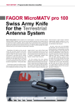
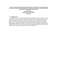
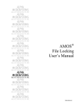
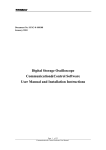
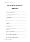
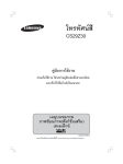
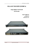
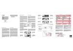
DEN 8000
Encoder
4xA/V
ASI
1
TABLE OF CONTENTS
1.- SAFETY INSTRUCTIONS
2.- SYSTEM PRINCIPLE
2.1 SYSTEM DIAGRAM
2.2 WORKING PRINCIPLE
2.2.1 VIDEO AUDIO A/D PROCESS
2.2.2 A/V ENCODING
2.2.3 AV TS PROCESS
2.2.4 DATA OUTPUT PORT
3.- SPECIFICATIONS
4.- EQUIPMENT CONNECTION
4.1 FRONT PANEL DISPLAY & KEY BUTTON
4.2 REAR PANEL
5. OPERATION
5.1 BASIC PROGRAMMING
5.2 MENU OPTION
5.2.1 LOCK STATUS DISPLAY
5.2.2 MAIN MENU DISPLAY
5.2.3 ENCODER SETTING
5.2.4 VIDEO SETTING
5.2.5 AUDIO SETTING
5.2.6 SYSTEM SETTING
5.2.7 OUTPUT SETTING
5.2.8 NETWORK SETTING
5.2.9 SAVE CONFIG
5.2.10 LOAD CONFIG.
5.2.11 VERSION
5.2.12 LANGUAGE
5.2.13 INFORMATION ERROR
6.- SYSTEM FAILURE & TROUBLE SHOOTING
6.1 INDICATOR STATUS
6.2 TROUBLE SHOOTING
7.- CE MARKING
2
1. SAFETY INSTRUCTION
● Read this manual carefully before use.
● Do not open the case without disconnecting it from the mains
● Allows the air circulation around the equipment
● Protects against the water or liquids drops on the equipment
● Do not place near to the heat sources.
● Do not obstruct he ventilation slots.
2. SYSTEM PRINCIPLE
2.1. SYSTEM DIAGRAM
3
2.2. WORKING PRINCIPLE
The DEN 8000 encoder structure is as per above picture, which consists of AV A/C process
unit, AV encoding unit, TS process unit, data output unit and CPU.
2.2.1 VIDEO AUDIO A/D PROCESS
AV A/D process unit converts analog audio & video input into digital format and send it to
encoding chipset. Video port supports ordinary signal source in broadcasting and various
standard video &audio signal ports, including analog CVBS input and mono, stereo audio
input. PAL/NTSC are both acceptable in this device.
2.2.2. A V ENCODING
AV encoding adopts MPEG-2 real-time encoding chipset, encoding the digital AV signal as
MPEG-2 format. The video encoding process is according to MPEG-2 main profile (MP@ML),
max bit rate is 15Mbps.The audio encoding process is done by professional audio encoding
software according to MPEG-2 layer I and layer II.
2.2.3. A V TS PROCESS
A V TS multiplexing includes the 4 routes ES to MPTS process. All data are MPEG-2
compliance.
2.2.4. DATA OUTPUT PORT
The output TS is compliant with DVB ASI.
3. SPECIFICATIONS
3.1. APPLICATION
The DEN 8000 encoder transforms the 4 input analogue A/V sources into a single DVB-ASI
digital stream.
3.2. CHARACTERISTICS
> Multiplexer function for up to 4 analogue A/V sources (PAL, NTSC).
> MPEG-2 MP@ML output video encoding, bit rate 1-15Mbps.
> MPEG-1 Layer 1, Layer 2 audio encoding.
4
> Programming via front panel (keyboard + LCD display) or PC (local or remote).
> Mountable in 19” rack.
> Includes:
- 4 x 3RCA-3BNC cables for 4 analogue A/V sources.
- 1 x BNC-F(m) cable for one COFDM output.
- 1 x user's manual.
- 1 x 230Vac cable.
5
4. EQUIPMENT CONNECTION
4.1. FRONT PANEL DISPLAY AND KEY BUTTON
1
2
3
4
5
6
7
LCD
Error indicator
POWER indicator
Directional arrow key
Enter
Exit
ENC 1~ENC4 Encoder Indicator
LEFT, RIGHT:move the cursors
UP, DOWN:change parameters
ENTER:confirm and operate
Exit:back to upper menu or cancel the setting
Note :
A、press ENTER and EXIT to unlock if device is in lock status
B、keyboard auto lock after 60 seconds without operation
C、in lock status, press “down” to see IP menu
6
4.2. REAR PANEL
1
CH1 A/V input
2
CH2 A/V input
3
CH3 A/V input
4
CH4 A/V input
5
ASI port (optional )/IP out( optional)
6
ASI output port 1
7
ASI output port 2
8
Ethernet port
9
Power switch
7
5. OPERATION
5.1.
BASIC PROGRAMMING GUIDE
Switch on the power switch 9; the Front panel “Power” LED will be on
Connect the A/V inputs: Yellow RCA to “CVBS”; White RCA to “L” input & Red RCA to
“R” input. When an useful signal is detected, the front panel ENC 1, ENC 2, ENC 3 or
ENC 4 will be on
• Connect the ASI output port 6 or 7 to the DMT 8000 ASI Input
• The output bit rate is factory preset at 26 Mbps and each encoder at 6 Mbps. Both
parameters can be modified by programming
• Service name edition ( Example Encoder 1): Section 5.2.6.4
o Encoder 1 > System > Program Name
If one of the inputs is not used, this input could be removed from the output MUX
Entering in: Encoder x > Multiplexing > YES/NO: Section 5.2.3
•
•
5.2.
MENU OPTION
5.2.1. LOCK STATUS DISPLAY
DEN 8000 4IN 1 Encoder
PG:04 BR:00.000Mbps
5.2.2. MAIN MENU DISPLAY
1. Encoder 1
2. Encoder 2
3. Encoder 3
4. Encoder 4
5. Output setting
6. Network setting
7. Save config.
8. Load config.
9. Version No.
10. Language
11. Error info
5.2.3. ENCODER SETTING: Each encoder can be programed using Up/Down keys and
pressing ENTER to confirm.
1.1 Multiplexing
1.1.1 Yes/No
1.2 Video
1.3Audio
1.4System
8
5.2.4. VIDEO SETTING: Select video config, LCD display as below :
1.2.1 Video Enable
1.2.2 Video mode
1.2.3 GOP
1.2.4 Brightness
1.2.5 Contrast
1.2.6 Saturation
1.2.7 Hue
1.2.8 Compression
5.2.4.1.
VIDEO ENABLE. The user can switch ON/OFF the video at the output
1.1.1VIDEO
ENABLE
1 On
0 Off
5.2.4.2.
VIDEO MODE: Three options can be chosen ( Auto, NTSC or PAL)
1.1.2 Video mode
Auto
NTSC
PAL
5.2.4.3.
VIDEO GOP: Four structures could be chosen, the IBBP is recommended
1.1.3GOP
I
IP
IBP
IBBP
5.2.4.4.
BRIGHTNESS: The image brightness is adjusted
1.1.4 Brightness
127
5.2.4.5.
CONTRAST : The video contrast is adjusted
1.1.5 Heft Contrast
127
5.2.4.6.
SATURATION: The color saturation is adjusted
1.1.6 Saturation
127
9
5.2.4.7.
HUE: The color hue is adjusted
1.1.7 Color
+000
5.2.4.8.
.
VIDEO COMPRESSION: The user can select one of them
1.1.8 Video compression
D1
3/4D1
2/3D1
HD1
SIF
5.2.5. AUDIO SETTING : The following parameters can be settled
1.2.1Coding Type
1.2.2Samping Freq.
1.2.3Output bit rate
1.2.4Audio mode
5.2.5.1.
AUDIO ENCODING TYPE :Two options can be chosen
1.2.1 Audio Encoding
Layer1
Layer2
5.2.5.2.
SAMPLING FREQUENCY: There are three sampling rates to select
1.2.2 Sampling rate
48 KHz
32 KHz
44.1 KHz
5.2.5.3.
AUDIO BITRATE SETTING: One of them can be chosen
1.2.3 Output bit rate
384Kbps
256Kbps
128Kbps
96 Kbps
64 Kbps
10
5.2.5.4.
AUDIO MODE: There are the following options
1.2.4 Audio mode
Stereo
Joined Stereo
Dual
Single Channel
Single
5.2.6. SYSTEM SETTING: The programmable parameters are
2.4.1 Encoding bitrate
2.4.2 Bitrate mode
2.4.3 Program provider
2.4.4 Program name
2.4.5 Program number
2.4.6 PMT PID
2.4.7 VIDEO PID
2.4.8 AUDIO PID
1.3.9 PCR PID
5.2.6.1.
ENCODING BITRATE: In this menu we can set the output bit rate of each
encoder, 6Mbps is settled as a factory default
2.4.1 Encoding bitrate
06.000Mbps
5.2.6.2.
BIT RATE MODE: In this menu the user can select the bit rate mode. CBR is
recommended
2.4.2 Bitrate mode
CBR
VBR
5.2.6.3.
PROGRAM PROVIDER: The program provider name could be edited
2.4.3 Provider
DTV
5.2.6.4.
PROGRAM NAME: The name of the program can be edited
2.4.4 Progr name
Encoder.1
11
5.2.6.5.
PROGRAM NUMBER: The user can set the program number
2.4.5 Progr number
0001
5.2.6.6.
PMT PID: The user can set the PMT and PID
2.4.6PMT PID
0256
5.2.6.7.
VIDEO PID: The user can set the video PID number
2.4.7VIDEO PID
0257
5.2.6.8.
AUDIO PID: The user can set the audio PID number
2.4.8 AUDIO PID
0258
5.2.6.9.
PCR PID : The user can set the PCR PID number
2.4.9 PCR PID
0259
5.2.7. OUTPUT SETTING: Press up/down to select the configuration
5 Output setting
5.1Output bit rate
5.2 TS ID
5.2.7.1.
OUTPUT BITRATE: The user can set the total output bit rate
5.1 Output bit rate
026.000Mbps
It should be higher than the total value of the 4 channel’s bit rate.
If each channel encoding bit rate is 6 mbps, the total value is 24 mbps, therefore it should
be settled 26 for example.
12
5.2.7.2.
TS ID: The user can set the TS ID
5.2 TS ID
00000
5.2.8. NETWORK SETTING : The user can define the following Network parameters for
Ethernet local or remote access
6.1 IP address
192.168.000.131
6.2 Sub net mask
255.255.255.000
6.3 gateway
192.168.000.001
6.4 NMS UDP port
2009
6.5 MAC address
00-45-34-84-02-21
5.2.9.
SAVE CONFIG: Press ENTER to save
7. Save Config.
Please Wait
5.2.10.
LOAD CONFIG: The user can choose one of them
8 Load conf.
8.1 Load Saved Config
8.2 Default Config
13
5.2.11.
VERSION: The Software and Hardware version are displayed
9. Version
SW:1.14 HW:1.03
5.2.12.
LANGUAGE: The display language is English
10 Languages
English
5.2.13.
ERROR MESSAGES: The display shows the systems errors
11 Error info
..
..
04: ASI Unlocked
6. SYSTEM FAILURE OR TROUBLE SHOOTING
6.1.
INDICATOR STATUS
There are 2 LED Indicators
1“POWER”: Green means right powering
2 “ERROR”: Red means system error
6.2.
TROUBLE SHOOTING
6.2.1 “POWER” OFF.- Check the mains connection
6.2.2 “ERROR” ON .- System error, check the display read-out
6.2.3 ENC INDICATOR OFF.- Check the A/V input connection and verify the type of
analogue signal (1 Vpp CVBS Video)
14
7.- CE MARKING
15
Fagor Electrónica, S.Coop.
San Andrés, s/n
E-20500 Mondragón (Spain)
Tel: + 34 943 71 25 26
Fax: + 34 943 71 28 93
www.fagorelectronica.com
16