1
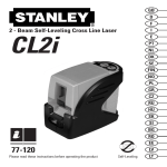
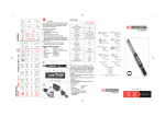
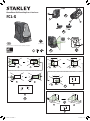
3
Green Beam Self-Levelling Cross Line Laser
4
2
FCL-G
A
4
1
7
6
B
8
GB
Self-Levelling
10
Please read these instructions before operating the product.
D
C
FMHT77348
D1
D1
D1
P1
D1
D1
2
P1
D1
2
P2
D1
2
P1
P1
D1
2
H1
H2
P1
P2
P3
D1
2
I1
P1
P4
P3
P2
D2
H3
D1
P1
P3
D4
D3
D2
P2
P2
P3
H4
D1
2
I3
P1
D1
2
I2
D1
2
P1
D2
P2
I4
I
P4
P2
P3
P1
H5
P4
P1
D1
H
L
D1
P2
2xL
P2
J
P3
2xL
J1
P1
L
P3
J2
P4
D2
J3
77-348 FCL-G - GB.indd 1
19/12/2014 11:10
Retain all sections of the manual for future reference.
Keypad-Pulse key.
User Safety
Pulse mode ON/OFF key (See figure D )
WARNING:
• Carefully read the Safety Instructions and Product Manual
before using this product. The person responsible for the
instrument must ensure that all users understand and adhere to
these instructions.
WARNING:
• The following labels are placed on the laser tool to inform you of
the laser class for your convenience and safety. (Text has been
translated here for your convenience)
Operation
to activate Pulse mode.(See figure D # 10 )
Press
Pulse Mode LED/Out-of-Level Indicator Operation (See figure D # 9 )
IEC /EN 60825-1
NOTE:
• It is best practice to always support laser tool with one hand when placing or
removing laser tool from an accessory.
• If positioning over a target, partially tighten the fastener, align laser tool,
and then fully tighten.
LED OFF
1. Pulse Mode is OFF/ Unit is level
LED ON-CONTINUOUS
2. PULSE MODE is ON, and laser unit is within self-leveling range
LED ON-FLASHING
3. Laser unit is OUT OF LEVEL.
Keypad-Battery key
Battery level indicator key (See figure D )
Complies with 21 CFR 1040.10 and 1040.11 except for deviations
pursuant to Laser Notice No. 50, dated June 2007
NOTE:
• Before operating the laser tool always be sure to check the laser tool for
accuracy.
• Laser tool will indicate when it is out of compensation range. Reference LED
Descriptions. Reposition laser tool to be closer to level.
• When not in use, please be sure to power OFF the laser tool by placeing the
pendulum lock in the locked position.
Power
• To turn the laser ON move the pendulum / transport lock to the unlocked
position.
• To turn the laser OFF, move the pendulum / transport lock to the locked
position.
Modes
OFF/ Locked (See figures B )
The laser will be OFF and the pendulum locked.
•
ON/ Self-Leveling (See figures B )
•
•
CAUTION:
• While the laser tool is in operation, be careful not to expose your
eyes to the emitting laser beam (red light source). Exposure to a
laser beam for an extended time may be hazardous to your eyes.
CAUTION:
• Glasses may be supplied in some of the laser tool kits. These are
NOT certified safety glasses. These glasses are ONLY used to
enhance the visibility of the beam in brighter environments or at
greater distances from laser source.
Contents
•
•
•
•
•
•
•
•
•
•
User Safety
Contents
Product Overview
Keypad, Modes, and LED
Applications
Batteries and Power
Set Up
Operation
Accuracy Check and Calibration
Specifications
Product Overview
Figure A - Laser Tool
1. Power /Transport Lock
2. Laser Window
3. Keypad
4. 1/4-20 threaded mount
5. 5/8-11 threaded mount
6. Battery Cover with Warning label
7. 4 x AA Batteries
Figure B - Power /Transport Lock
Figure C - Laser Modes
Figure D - Keypad
Battery Life LED (See figure D # 8)
LED OFF
1. Battery life >25%
LED ON-CONTINUOUS
2. Battery life < 25%
Applications
Plumb Transfer
• Using the vertical laser beam, establish a vertical reference plane.
• Position the desired object(s) until they are aligned with the vertical reference
plane to ensure object(s) are plumb.
Level Transfer
•Using the horizontal laser beam, establish a horizontal reference plane.
•Position the desired object(s) until they are aligned with the horizontal
reference plane to ensure object(s)are level.
Square
• Using the vertical and horizontal laser beams, establish a point where the two
beams cross.
• Position the desired object(s) until they are aligned with both the vertical and
horizontal laser beams to ensure objects(s) are square.
Figure J - Vertical Beam Accuracy
Keypad, Modes, and LED
Switch
Power ON/Pendulum lock off /Self-leveling On
Power OFF/Pendulum lock on
• To turn the laser tool ON move switch to the unlocked position
• To turn the laser tool OFF, move switch to the locked position
Modes
Laser Beam Available Modes
• All beam lines ON
• All beam lines OFF
Self-Leveling (See figure B )
• The pendulum lock on the laser tool needs to be switched to the unlocked /
ON position to enable self-leveling.
77-348 FCL-G - GB.indd 2
Accuracy Check and Calibration
NOTE:
• The laser tools are sealed and calibrated at the factory to the accuracies
specified.
• It is recommended to perform a calibration check prior to its first use and
then periodically during future use.
• The laser tool should be checked regularly to ensure its accuracies,
especially for precise layouts.
• When performing the accuracy checks, use the largest area / distance
possible, closest to the operating distance. The greater the area / distance,
the easier to measure the accuracy of the laser.
• The lock must be in the unlocked position to allow the laser tool to self-level
before checking the accuracy.
Level Beam Accuracy (See figure H )
•
H
•
•
•
•
H
Place laser tool as shown with laser ON. Mark point P1 at cross.
Rotate laser tool 180° and mark point P2 at cross.
H Move laser tool close to wall and mark point P at cross.
3
3
H Rotate laser tool 180° and mark point P at cross.
4
4
H Measure the vertical distance between P and P to get D and the
5
1
3
3
vertical distance between P2 and P4 to get D4 .
• Calculate the maximum offset distance and compare to the difference of
D3 and D4 as shown in the equation.
• If the sum is not less than or equal to the calculated maximum
offset distance the tool must be returned to your Stanley
Distributor for calibration.
1
2
Maximum Offset Distance:
Batteries and Power
Battery Installation / Removal (See figure B )
Laser Tool
• Turn laser tool to battery door and open.
• Install / Remove batteries. Orient batteries correctly when placing into
battery compartment.
• Close battery door. Be sure that the door has been closed securely.
Maximum
= 0,6 mm
m x (D1 m - (2 x D2 m))
= 0,007 in
ft x (D1 ft - (2 x D2 ft))
Compare : (See figure
H
5
)
D3 - D4 ≤ ± Maximum
Figure H - Level Beam Accuracy
Figure I - Horizontal Beam Accuracy
The pendulum lock on the laser tool will be positioned in the unlocked
/self-leveling position when the laser is turned ON
WARNING:
• Pay close attention to the battery holder’s (+) and (-) markings
for proper battery insertion. Batteries must be of same type and
capacity. Do not use a combination of batteries with different
capacities remaining.
Set Up
Laser Tool
• Place laser tool on a flat, stable surface.
• To power ON and activate the auto leveling feature move the pendulum
/ transport lock to the unlocked position. The laser tool must then be
positioned in its upright position on a surface that is within the specified
compensation range.
Example:
• D1 = 10 m, D2 = 0,5 m
• D3 = 0,5 mm
• D4 = - 1,0 mm
• 0,6 mm
m x (10 m - (2 x 0,5 m) = 5.4 mm
(maximum offset distance)
• (0,5 mm) - (- 1,0 mm) = 1,5 mm
• 1,5 mm ≤ 5.4 mm
(TRUE, tool is within calibration)
Mounting on Accessories
• Position accessory in a place where it will not be easily disturbed and
near the central location of the area to be measured.
• Set up the accessory as required. Adjust positioning to be sure accessory
base is near horizontal (within laser tools compensation range).
• Mount the laser tool to the accessory using the appropriate fastening
method to be used with such accessory / laser tool combination.
CAUTION:
• Do not leave the laser tool unattended on an accessory without
fully tightening the fastening screw. Failing to do so may lead to
the laser tool falling and sustaining possible damage.
19/12/2014 11:10
Horizontal Beam Accuracy (See figure I )
•
•
•
•
•
•
Vertical Beam Accuracy (See figure
Place laser tool as shown with laser ON. Aim vertical beam towards
the first corner or a set reference point. Measure out half of the distance
D1 and mark point P1 .
I
2 Rotate laser tool and align front vertical laser beam with point P .
1
Mark point P2 where the horizontal and vertical laser beams cross.
I
3 Rotate laser tool and aim vertical beam towards the second corner
or set reference point. Mark point P3 so that it is vertically in line with
points P1 and P2 .
I
4 Measure the vertical distance D between the highest and lowest
2
point.
Calculate the maximum offset distance and compare to D2 .
If D2 is not less than or equal to the calculated maximum offset
distance the tool must be returned to your Stanley Distributor for
calibration.
I
1
Maximum Offset Distance:
= 0,3 mm
m x D1 m
Maximum
D2 ≤ Maximum
Example:
• D1 = 10m, D2 = 1,0 mm
• 0,3 mm
m x 10 m = 3mm
(maximum offset distance)
• 1,0 mm ≤ 1,0 mm
(TRUE, tool is within calibration)
•
•
•
•
Specifications
)
Measure the height of a door jamb or reference point to get distance
D1 . Place laser tool as shown with laser ON. Aim vertical beam towards
door jamb or reference point. Mark points P1 , P2 , and P3 as shown.
J
2 Move laser tool to opposite side of door jamb or reference point and
align the same vertical beam with P2 and P3 .
J
3 Measure the horizontal distances between P and the vertical beam
1
from the 2nd location.
Calculate the maximum offset distance and compare to D2 .
If D2 is not less than or equal to the calculated maximum offset
distance the tool must be returned to your Stanley Distributor for
calibration.
1
Maximum Offset Distance:
Maximum
4
FCL-G (STHT77348)
Levelling Accuracy:
≤3 mm / 10m (1/8in @ 30 ft)
Horizontal / Vertical
Accuracy
≤3mm / 10m (1/8in @ 30 ft)
Compensation Range:
Working Distance
(Line):
Laser Class:
± 4°
20 m (65ft)
Class 2 (IEC/EN60825-1)
= 0,6 mm
m x D1 m
Laser Wavelength
510 nm ~ 530 nm
= 0,004 in
ft x D1 ft
Operating Time (All
lasers ON):
≥ 10 hours (Alkaline)
J
3
)
D2 ≤ Maximum
I
Laser Tool
J
Compare: (See figure
= 0,004 in
ft x D1 ft
Compare: (See figure
•
J
)
Example:
• D1 = 2 m, D2 = 0,5 mm
• 0,6 mm
m x 2 m = 1,2 mm
(maximum offset distance)
• 0,5 mm ≤ 1,2mm
(TRUE, tool is within calibration)
Power Source:
IP Rating:
4 x “AA” (LR6)
IP54
Temperature Range
(Operating):
-10° C ~ +50° C (14°F ~ 122°F)
Temperature Range
(Storage):
-25° C ~ +70° C (-13°F~158°F)
© 2014 Stanley Black and Decker, Inc,
Egide Walschaertsstraat 14-16,
2800 Mechelen, Belgium
www.STANLEYTOOLS.eu
© 2014 Stanley Tools,
701 East Joppa Road,
Baltimore, Maryland 21286
www.STANLEYLASERS.com
77-348 FCL-G - GB.indd 3
19/12/2014 11:10