1
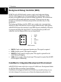
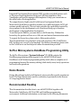
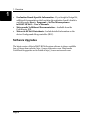
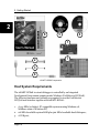
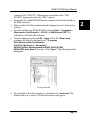
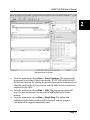
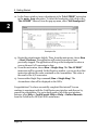
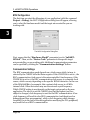
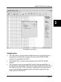
®
inDART -HCS08
In-Circuit
Debugger/Programmer
for Motorola HCS08 Family
FLASH Devices
User’s Manual
Copyright © 2003 SofTec Microsystems®
DC00634
We want your feedback!
SofTec Microsystems is always on the look-out for new ways to improve its
Products and Services. For this reason feedback, comments, suggestions or
criticisms, however small, are always welcome.
SofTec Microsystems
E-mail (general information): [email protected]
E-mail (marketing department): [email protected]
E-mail (technical support): [email protected]
Web: http://www.softecmicro.com
Important
SofTec Microsystems reserves the right to make improvements to the inDART® Series In-Circuit
Debuggers, their documentation and software routines, without notice. Information in this manual
is intended to be accurate and reliable. However, SofTec Microsystems assumes no responsibility for
its use; nor for any infringements of rights of third parties which may result from its use.
SOFTEC MICROSYSTEMS WILL NOT BE LIABLE FOR DAMAGES RESULTING FROM LOSS OF
DATA, PROFITS, USE OF PRODUCTS, OR INCIDENTAL OR CONSEQUENTIAL DAMAGES,
EVEN IF ADVISED OF THE POSSIBILITY THEREOF.
Trademarks
inDART is a trademark of SofTec Microsystems.
Motorola and DigitalDNA are trademarks or registered trademarks of Motorola, Inc.
Metrowerks and CodeWarrior are trademarks or registered trademarks of Metrowerks Corp.
Microsoft and Windows are trademarks or registered trademarks of Microsoft Corporation.
PC is a registered trademark of International Business Machines Corporation.
Other products and company names listed are trademarks or trade names of their respective
companies.
Written by Paolo Xausa
inDART-HCS08 User's Manual
Contents
1. Overview
What is inDART-HCS08?
Background Debug Controller (BDC)
CodeWarrior Integrated Development Environment
SofTec Microsystems DataBlaze Programming Utility
Demo Boards
Recommended Reading
Software Upgrades
2. Getting Started
inDART-HCS08 Components
Host System Requirements
Installing the Software
Installing Metrowerks CodeWarrior IDE
Installing SofTec Microsystems Additional Components
Installing the Hardware
Application Tutorial
3. inDART-HCS08 Operations
inDART-HCS08 Working Principles
Configuring a Debugging Session
Creating Your Own Application
MCU Configuration
Communication Settings
Breakpoints and Trace
Using Existing Projects with inDART-HCS08
Notes and Tips
Entering Debug Session with CodeWarrior
Reading Peripheral Status
Breakpoints and BGND Instruction
Real-Time Memory Update
DataBlaze Programming Utility
DataBlaze Notes
5
5
6
6
7
7
7
8
9
9
10
11
11
11
12
14
19
19
19
19
20
20
21
22
23
23
23
23
23
24
25
Contents
4. Troubleshooting
Common Problems and Solutions
Communication Can’t Be Established with inDART-HCS08
Stepping Execution is Slow
STOP Assembly Instruction Causes a Microcontroller Reset
Communication Lost During Debugging
Diagnostic Test
Getting Technical Support
Appendix A. Electrical and Physical Specifications
27
27
27
28
28
28
28
29
31
inDART-HCS08 User's Manual
1
1. Overview
What is inDART-HCS08?
inDART-HCS08 is a powerful entry-level tool for Motorola HCS08-based
systems. inDART-HCS08 takes advantage of Metrowerks CodeWarrior HC(S)08
Integrated Development Environment and the BDC (Background Debug
Controller) feature to debug the user program. Together with CodeWarrior
HC(S)08, inDART-HCS08 provides you with everything you need to compile,
download (program), in-circuit emulate and debug user code. Full speed
program execution allows you to perform hardware and software testing in real
time. inDART-HCS08 is connected to the host PC through a USB port, while the
6-pin BDM connector of the product fits into the target’s standard BDM
connector. Design Kit packages also include a full-featured experiment board
for a specific HCS12 microcontroller.
inDART-HCS08 offers you the following benefits:
§
§
§
§
§
§
§
§
§
§
§
Real-time code execution without probes–works with all packages (BDMcompatible connector);
In-circuit debugging;
Built-in FLASH programmer (DataBlaze programming utility);
1.8 to 5.5 V devices supported;
Standard chip used—no bondouts, 100% electrical characteristics
guaranteed;
Working frequency up to the microcontroller’s maximum;
Jumperless hardware mode setting;
Automatic target frequency detection;
Hardware self diagnostic test;
USB connection to the PC;
Metrowerks CodeWarrior IDE (the same user interface of all Motorola
tools), with editor, assembler, C compiler and debugger.
Page 5
1. Overview
1
Background Debug Controller (BDC)
All MCUs in the HCS08 family contain a single-wire background debug
interface which supports in-circuit programming of on-chip non-volatile
memory and sophisticated non-intrusive debug capabilities. This system does
not interfere with normal application resources. It does not use any user
memory or locations in the memory map and does not share any on-chip
peripherals.
The background debug controller (BDC) uses a single-wire communication
interface to allow non-intrusive access to target system memory and registers.
inDART-HCS08 uses the standard, 6-pin BDM connector defined by Motorola
to program and debug the target device. You must therefore provide such
connector (see the diagram below) on your target board.
1
2
3
4
5
6
1
BKGD
2
GND
3
N.C.
4
RESET#
5
N. C.
6
VDD
BDM Connector
§
§
§
§
BKGD: Single-wire background interface pin. This signal is required.
GND: System ground. This signal is required.
RESET#: Reset signal to target system. This signal is optional but it’s
useful during debugging.
VDD: Power supply voltage from target. This signal is required by inDARTHCS08 signal conditioning.
CodeWarrior Integrated Development Environment
inDART-HCS08 comes with a free version of CodeWarrior Development Studio
for HC(S)08 Microcontrollers, Special Edition.
CodeWarrior Development Studio for HC(S)08 is a powerful and easy-to-use
tool suite designed to increase your software development productivity. Its
Page 6
inDART-HCS08 User's Manual
Integrated Development Environment (IDE) provides unrivaled features such
as Processor Expert application design tool, full chip simulation, Data
Visualization and project manager with templates to help you concentrate on
the added value of your application.
The comprehensive, highly visual CodeWarrior Development Studio for
Motorola HC(S)08 Microcontrollers enables you to build and deploy HC(S) 08
systems quickly and easily. This tool suite provides the capabilities required by
every engineer in the development cycle, from board bring-up to firmware
development to final application development.
To use the Special Edition, you must have a valid license key. Without the
license key the product will run in a 1 KB code-size limited demonstration mode.
To request the license key, please refer to Metrowerks website.
This documentation covers the basic setup and operation of the CodeWarrior
IDE, but does not cover all of its functions. For further information, please refer
to the CodeWarrior on-line help and online documentation provided.
SofTec Microsystems DataBlaze Programming Utility
The SofTec Microsystems “System Software” CD-ROM contains the
DataBlaze programming utility targeted to the inDART-HCS08 board.
DataBlaze is a full-featured programming utility which offers a complete set of
programming features like memory editing, blank check/erase/verify operations
and read/write operations.
Demo Boards
Design Kit packages include a full-featured, microcontroller-specific experiment
board. The demo board can be used for evaluation/experiments in the absence
of a target application board.
Recommended Reading
This documentation describes how to use inDART-HCS08 together with
Metrowerks CodeWarrior HC(S)08 IDE and DataBlaze programming
environment. Additional information can be found in the following documents:
Page 7
1
1. Overview
1
§
§
§
Evaluation Board-Specific Information—If you bought a Design Kit,
additional documentation which explains the evaluation board’s details is
available under Start > Programs > SofTec Microsystems >
inDART-HCS08 > User’s Manuals.
Metrowerks’ Additional Documentation— Available from the
CodeWarrior IDE.
Motorola HCS08 Datasheets—Include detailed information on the
devices’ background debug controller (BDC).
Software Upgrades
The latest version of the inDART-HCS08 system software is always available
free of charge from website: http://www.softecmicro.com. Metrowerks
CodeWarrior upgrades can be found at http://www.metrowerks.com.
Page 8
inDART-HCS08 User's Manual
2. Getting Started
2
inDART-HCS08 Components
The inDART-HCS08 package includes the following items:
1.
2.
3.
4.
5.
6.
7.
The inDART-HCS08 in-circuit debugger/programmer unit;
A 20-cm, 6-conductor BDM cable;
A 30-cm, 1-conductor “VDD OUT” cable;
A USB cable;
The Metrowerks CodeWarrior HC(S)08 CD-ROM;
The SofTec Microsystems inDART-HCS08 “System Software” CD-ROM;
A full-featured, microcontroller-specific experiment board (Design Kit
packages only);
8. This user’s manual.
Page 9
2. Getting Started
2
8
5
6
1
7
2
3
4
inDART-HCS08 Components
Host System Requirements
The inDART-HCS08 in-circuit debugger is controlled by an Integrated
Development Environment running under Windows (CodeWarrior HC(S)08).
The following hardware and software are required to run the CodeWarrior
HC(S)08 user interface together with inDART-HCS08:
1.
A 133-MHz (or higher) PC compatible system running Windows 98,
Windows 2000 or Windows XP;
2. 128 MB of available system RAM plus 500 MB of available hard disk space;
3. A USB port;
Page 10
inDART-HCS08 User's Manual
4. CD-ROM drive for installation.
Installing the Software
inDART-HCS08 requires that both Metrowerks CodeWarrior IDE and SofTec
Microsystems inDART-HCS08 additional components be installed in the host
PC.
Note: Metrowerks CodeWarrior HC(S)08 IDE must be installed first. Please
note that inDART-HCS08 only works with CodeWarrior for HC(S)08 version
3.0 or above.
Installing Metrowerks CodeWarrior IDE
To install the CodeWarrior IDE insert the CodeWarrior CD-ROM into your
computer’s CD-ROM drive. A startup window will automatically appear. Follow
the on-screen instructions.
Installing SofTec Microsystems Additional Components
SofTec Microsystems additional components install all of the other required
components to your hard drive. These components include:
§
§
§
§
§
§
The inDART-HCS08 USB driver;
inDART-HCS08 software plug-in for CodeWarrior HC(S)08;
Sample source code for SofTec Microsystems evaluation boards;
SofTec Microsystems DataBlaze programming utility;
inDART –HCS08 hardware diagnostic test utility;
Documentation in PDF format.
To install SofTec Microsystems additional components insert the SofTec
Microsystems “System Software” CD-ROM into your computer’s CD-ROM
drive. A startup window will automatically appear. Choose “Install
Instrument Software” from the main menu. A list of available software will
Page 11
2
2. Getting Started
appear. Click on the “inDART-HCS08 Additional Components” option.
Follow the on-screen instructions.
2
Note: if you are installing the inDART-HCS08 additional components on
Windows 2000 or Windows XP you must have logged in as Administrator.
Installing the Hardware
The inDART-HCS08 in-circuit debugger is connected through a USB port to a
host PC. Connection steps are listed below in the recommended flow order:
1. Install all the required system software as described in the previous section.
2. Insert one end of the USB cable into a free USB port.
3. Insert the other end of the USB cable into the “USB” connector on the
inDART-HCS08 board. The green “POWER” LED on the instrument should
turn on. Windows will automatically recognize the instrument and will load
the appropriate USB driver.
4. Insert one end of the BDM cable into the 6-way “BDM” connector on the
inDART-HCS08 board.
5. Insert the other end of the BDM cable into the BDM connector of the demo
board or target application.
6. Power the demo board or target application. When using a SofTec
Microsystems demo board, there are two power options:
a.
Page 12
Power the board via the “UNREG. VDD” connector: The
“UNREG. VDD” connector accepts 9-12 V DC, 200-mA wall plug-in
power supply with a 2.1 mm pin and sleeve plug with positive in the
center and sleeve as ground. When powering the board through
this connector, make sure the “VDD SOURCE” jumper selects the
“UNREG.” position. The “UNREG. VDD” voltage is internally
regulated to the microcontroller’s operating voltage (3.0 V DC in
the case of the MC9S08GB60).
inDART-HCS08 User's Manual
b.
Power the board via the “REG. VDD” connector: The “REG.
VDD” connector accepts a voltage up to the microcontroller’s
operating voltage (3.3 V DC in the case of the MC9S08GB60).
When powering the board through this connector, make sure the
“VDD SOURCE” jumper selects the “REG.” position. The “REG.
VDD” voltage directly powers the microcontroller and the rest of
the board. The “REG. VDD” connector has been designed to be
used together with inDART-HCS08’s “VDD OUT” connector: the
“VDD OUT” cable can be conveniently inserted into the “VDD
OUT” connector on the inDART-HCS08 board and into the “REG.
VDD” connector on the demo board. This way inDART-HCS08
powers the demo board.
Please refer to the following figure to get an overview of the inDART-HCS08
unit.
1
2
3
1. USB Connector
2. BDM Connector
3. “VDD OUT” Connector
The inDART-HCS08 Unit
Page 13
2
2. Getting Started
2
Note: both Windows 2000 and Windows XP may issue a warning the first
time inDART-HCS08 is connected to the PC. This warning is related to the fact
that the USB driver used by inDART-HCS08 is not digitally signed by
Microsoft, and Windows considers it to be potentially malfunctioning or
dangerous for the system. However, you can safely ignore the warning, since
every kind of compatibility/security test has been carried out by SofTec
Microsystems. Additionally, under Windows XP, the “Found New Hardware
Wizard” procedure may occur twice.
Application Tutorial
This section will provide a step-by-step guide on how to launch your first
inDART-HCS08 project and get started with the CodeWarrior HC(S)08 user
interface.
Note: the example provided assumes that inDART-HCS08 is used with the
IDB-HCS08GB demo board. If you have a different demo board, some
procedures may differ slightly. This tutorial is based on an Assembly example.
Additional examples in C are also provided. For evaluation board-specific
features, please refer to the evaluation boards’ PDF manuals installed by
SofTec Microsystems additional components.
The sample application does the following:
§
§
1.
By rotating the potentiometer, you affect the results of the A/D conversion,
and the value of each conversion is displayed on the LEDs;
By pressing the PTC5 push button, the DIP-switches status is displayed on
the LEDs.
Ensure that the inDART-HCS08 board is connected to the PC (via the USB
cable) and that the demo board is powered on via the “REG. VDD”
Page 14
inDART-HCS08 User's Manual
2.
3.
4.
5.
connector (the “VDD OUT” cable must be connected and the “VDD
SOURCE” jumper must select the “REG.” option).
Ensure that the inDART-HCS08 board is connected to the demo board via
the BDM connector.
Make sure that all of the evaluation board’s jumpers are set to their factory
position.
Start the CodeWarrior HC(S)08 IDE by selecting Start > Programs >
Metrowerks CodeWarrior > CW08 > CodeWarrior IDE. The
CodeWarrior HC(S)08 IDE will open.
From the main menu, choose File > Open. Select the “Demo.mcp”
workspace file that is located under the “\Program
Files\Metrowerks\CodeWarrior
CW08\(CodeWarrior_Examples)\
HCS08\SofTec Microsystems\inDART-HCS08\IDBHCS08GB\Asm\Demo” directory. Click “Open”. The following window
will appear.
The Project Window
6. The Assembly code of this example is contained in the “main.asm” file.
Double click on it to open it. The following window will appear.
Page 15
2
2. Getting Started
2
The Example’s Source Code
7.
From the main menu, choose Project > Debug. This will generate an
executable file and will download it to the demo board.
8. A new debugger environment will open. In the Source window, the first line
to be executed is highlighted.
Page 16
inDART-HCS08 User's Manual
2
Debugging Session Started
9. From the main menu, choose Run > Start/Continue. The program will
be executed in real-time. Please note that the “BUSY” LED on the inDARTHCS08 unit turns on. By rotating the potentiometer on the demo board, you
affect the results of the A/D conversion, and the value of each conversion is
displayed on the LEDs.
10. From the main menu, choose Run > Halt. The program execution will
stop. The next instruction to be executed is highlighted in the Source
window.
11. From the main menu, choose Run > Single Step. The instruction
highlighted in the Source window will be executed, and the program
execution will be stopped immediately after.
Page 17
2. Getting Started
12. In the Source window, insert a breakpoint at the “lda ATDRH” instruction
in the main_loop subroutine. To insert the breakpoint, right-click on the
“lda ATDRH” line and, from the pop-up menu, select “Set Breakpoint”.
2
Breakpoint Set
13. Rotate the potentiometer slightly. Then, from the main menu, choose Run
> Start/Continue. The application will restart from where it was
previously stopped. The application will stop at the breakpoint location as
soon as the next A/D conversion is done.
14. From the main menu, choose Run > Single Step. The “lda ATDRH”
instruction will be executed. In the Registers window, you can see how that
instruction affected the value contained on the Accumulator. This value is
the result of the A/D conversion.
15. Issue another Single Step command (Run > Single Step). The
Accumulator value will be displayed on the LEDs.
Congratulations! You have successfully completed this tutorial! You can
continue to experiment with the CodeWarrior user interface and discover by
yourself its potentialities. For an in-depth guide of all of the user interface
features, select Help > CodeWarrior Help or Help > Online Manuals
from the CodeWarrior HC(S)08 IDE’s main menu.
Page 18
inDART-HCS08 User's Manual
3. inDART-HCS08 Operations
inDART-HCS08 Working Principles
inDART-HCS08 is an in-circuit debugger as well as a programming tool. It
programs files into the HCS08 microcontrollers and offers debugging features
like real-time code execution, stepping, advanced breakpoints and trace buffer.
Its debugging features are achieved thanks to the microcontroller’s integrated
Background Debug Controller (BDC).
The BDC peripheral communicates with the inDART-HCS08 board through a
single-wire dedicated line of the microcontroller. The same line is also used
during device programming.
Contrariwise to traditional in-circuit emulation (where the target application is
executed and emulated inside the emulator), inDART-HCS08 uses the very
same target microcontroller to carry on in-circuit execution. This means that all
microcontroller’s peripherals (timers, A/D converters, I/O pins, etc.) are not
reconstructed or simulated by an external device, but are the very same target
microcontroller’s peripherals. Moreover, the inDART-HCS08 debugging
approach ensures that the target microcontroller’s electrical characteristics
(pull-ups, low-voltage operations, I/O thresholds, etc.) are 100% guaranteed.
Configuring a Debugging Session
Creating Your Own Application
CodeWarrior HC(S)08 helps you get started with your own application by
including a project wizard specific for the inDART-HCS08 board. To create a
new inDART-HCS08 project:
1. From the main menu, select File > New.
2. A dialog box will appear. Select “HC(S)08 New Project Wizard”.
3. Follow the Project Wizard steps, making sure you select the correct
microcontroller derivative you are working with and the inDART-HCS08
board as emulator.
Page 19
3
3. inDART-HCS08 Operations
MCU Configuration
The first time you start the debugging of your application (with the command
Project > Debug), the MCU Configuration dialog box will appear, allowing
you to select the hardware model and the target microcontroller you are
working with.
3
The MCU Configuration Dialog Box
First, ensure that the “Hardware Model” parameter is set to “inDARTHCS08”. Then, set the “Device Code” parameter to the specific target
microcontroller you are working with. Additional communication parameters
can be specified by clicking the “Communication Settings” button.
Communication Settings
The BDC communication speed depends on a clock source which, in turn, is
selected by the CLKSW bit in the Status register. If the CLKSW bit is set to 1, the
BDC communication clock source is the microcontroller’s bus frequency; if the
CLKSW bit is set to 0, the BDC communication clock source is a constant clock
source, which can vary depending on the specific HCS08 derivative. In the case
of the MC9S08GB60, for example, this constant clock source is a 8 MHz
internal clock. Other derivatives may use the external crystal frequency.
Which CLKSW setting to use depends on the target system and on the user
application. The idea is to set the CLKSW bit so that the highest (and less
subject to changes) clock frequency is used for the BDC communication. A low
clock frequency will result in slow BDC communication (and therefore slow
debugging and slow programming), while a clock frequency which changes
frequently (as in the case of the user application modifying the FLL peripheral)
may result in loss of BDC communication.
Page 20
inDART-HCS08 User's Manual
The value of the CLKSW can be changed in the Communication Settings dialog
box.
3
The Communication Settings Dialog Box
Breakpoints and Trace
CodeWarrior offers a variety of tools for analyzing the program flow:
breakpoints (both simple and complex), watchpoints and a trace buffer. All
these features are implemented by taking advantage of the target
microcontroller’s DBG peripheral.
To access breakpoints, watchpoints and trace buffer settings, open the Trigger
Module Settings dialog box by choosing the SofTec-HCS08 > Trigger
Module Settings menu while in debug.
When setting an instruction breakpoint, CodeWarrior does the following:
1.
If available, uses the hardware address breakpoint built into the BDC
module;
2. Otherwise, if possible, sets one hardware breakpoint using the DBG
peripheral;
3. If no hardware breakpoints are available in the DBG peripheral (or if the
trigger mode is not set to “Automatic”), a warning message is displayed, and
the instruction breakpoint will not be set.
Page 21
3. inDART-HCS08 Operations
Note: when setting an instruction breakpoint on a RAM location, a software
breakpoint is set (the opcode present at that location is automatically replaced
by the BGND Assembly instruction). Therefore, no hardware breakpoints are
wasted.
3
Note: the Single Step command (in a C source code) and the Step Over and
Step Out commands (both in a C and Assembly source code) use one hardware
breakpoint.
Using Existing Projects with inDART-HCS08
If your project has been targeted to an emulator/simulator other than inDARTHCS08 and you wish to use inDART-HCS08 as the debugger for your project,
please do the following:
1.
CodeWarrior is interfaced to the inDART-HCS08 engine through a so-called
“GDI interface”. From the CodeWarrior HC(S)08 debugger interface, select
Component > Set Target and choose “HCS08” as processor and “GDI
Target Interface” as target interface.
2. A dialog box will appear asking you to locate the GDI dll file needed to
interface with inDART-HCS08. Select the SofTec_BDC08.dll file located
into the \Program Files\Metrowerks\CodeWarrior CW08\prog\
directory.
3. CodeWarrior will then recognize inDART-HCS08 as the target interface for
your project. The MCU Configuration dialog box will appear allowing you to
select the derivative you are working with.
4. On the CodeWarrior HC(S)08 debugger interface a new menu (SofTecHCS08) will be created. From this menu, select Load and locate the object
file your project is based on.
Page 22
inDART-HCS08 User's Manual
Notes and Tips
Entering Debug Session with CodeWarrior
When entering a debug session, the target microcontroller’s FLASH memory is
automatically erased, unsecured, programmed with the user application, and
the trimming value (if trimming is available for the selected microcontroller) is
automatically calculated and programmed (to the location suggested by
Motorola).
Note: When programming the microcontroller with the user application
(after having unsecured the device), CodeWarrior ignores (doesn’t program)
the security bits. As a result, when entering a debug session, the device is
always unsecured, regardless of other user settings.
Reading Peripheral Status
Care must be taken when reading some peripheral’s status/data registers, since
a reading operation may cause the clearing of flags. This may happen when the
Memory window or the Data window is open, since these windows read
microcontroller’s resources during refresh operations.
Breakpoints and BGND Instruction
The BGND Assembly instruction forces the target microcontroller to enter the
Active Background Debug mode, stopping program execution. CodeWarrior
recognizes this event as a breakpoint and updates the contents of registers,
memory, etc. Successive commands (Start/Continue, Single Step, etc.) will
continue the execution of the program from the next instruction.
Real-Time Memory Update
During program execution, it is possible to view/edit the contents of the
Memory window and Data window in real time (edit operations are only
available for RAM locations). For example, it is possible to set the periodical
refresh of the Memory window contents by choosing Mode > Periodical from
the pop-up menu which appears by right-clicking on the Memory window.
Page 23
3
3. inDART-HCS08 Operations
DataBlaze Programming Utility
A full-featured programming utility (DataBlaze) is also provided with inDARTHCS08. To start the DataBlaze utility select Start > Programs > SofTec
Microsystems > inDART-HCS08 > DataBlaze Programmer.
DataBlaze offers the following advanced features:
3
§
§
§
§
§
§
§
§
Code memory editing;
Data memory (EEPROM) editing;
Blank check/erase/program/verify operations on Code memory and Data
memory;
Read operations from Code memory and Data memory;
Project handling;
One-button, multiple-operations programming (“Auto” feature);
Automatic trimming calibration;
Serial numbering.
Page 24
inDART-HCS08 User's Manual
3
The DataBlaze User Interface
DataBlaze Notes
§
§
§
The “Mass Erase” operation always blanks the device (even if the device is
protected or secured) and “unsecures” the device (the NVOPT FLASH
register is programmed with 0xFE).
The “Blank Check” operation doesn’t blank check the NVOPT FLASH
register.
The “Program” operation automatically verifies the programmed data, by
reading back the programmed data and checking it against the buffer sent to
the target device. The “Verify” operation is much more secure (but slower),
since it reads back the programmed data and checks it against the data
buffer present in the host PC.
Page 25
3. inDART-HCS08 Operations
§
§
§
3
In case of programming error, please verify that the NVOPT FLASH register
is programmed with a value different from 0xFF.
The “Read”, “Program” and “Verify” operations are performed (when
possible) by setting the target microcontroller’s FLL peripheral so that the
maximum BDC communication speed is achieved.
On all devices which support the trimming calibration, the FLASH location
suggested by Motorola where to store the trimming value is reserved by
DataBlaze. DataBlaze automatically calculates the trimming value and
writes it to that location.
Page 26
inDART-HCS08 User's Manual
4. Troubleshooting
Common Problems and Solutions
This section reports some common problems that may arise during general use.
However, working with a specific target device may cause device-specific issues.
Communication Can’t Be Established with inDART-HCS08
1.
Make sure the inDART-HCS08 in-circuit debugger is connected to the PC
and powered on. inDART-HCS08 is powered by the USB connection.
2. Make sure you are working with the correct inDART hardware model. To
view/change the inDART hardware model in use, choose inDART-HCS08
> MCU Configuration the CodeWarrior HC(S)08 debugger’s main menu.
3. If the inDART-HCS08 menu is not present in the CodeWarrior HC(S)08
debugger’s main menu, this is because the target has not been recognized by
CodeWarrior (“No link to Target” appears in the status bar). In this case,
you must do the following:
§
§
From the GDI menu, choose MCU Configuration and verify that the
hardware code and device code parameters are set correctly.
Press the “Communication Settings” button and verify that all of
the communication parameters are set correctly.
4. Make sure the demo board/target application board is powered on and the
target microcontroller is working. Programming and debugging rely on a
BDM communication between the inDART-HCS08 board and the demo
board/target application. This means that, in order to work correctly, the
target microcontroller must be running. In particular, make sure that:
§
§
The BDM cable is connected to the demo board/target application’s
BDM connector.
All of the required BDM connector signals are correctly tied to the target
microcontroller.
Page 27
4
4. Troubleshooting
Stepping Execution is Slow
When the Memory window is open, step commands may execute slower, since
the Memory window contents need to be refreshed after every step.
STOP Assembly Instruction Causes a Microcontroller Reset
If the STOPE bit in the SOPT register is not set, the STOP instruction is
recognized as an illegal opcode, causing the microcontroller to reset. The SOPT
register can be written only once after reset.
4
Communication Lost During Debugging
This problem may have several causes:
1.
The microcontroller’s bus frequency has been changed by the user
application and the CLKSW bit is set to 1. In this case, set the CLKSW bit to
0 (in the Communication Settings dialog box).
2. The BKGDPE bit in the SOPT (System Option Register) register has been
set to 0, configuring the BKGD pin as a generic I/O pin. The BKGD pin must
be reserved for the BDC communication (BKGDPE = 1).
3. A microcontroller reset has occurred. Among other things, this may be
caused by the COP peripheral. After reset, the COP is enabled, so your
program must either disable it or reset its timer.
Diagnostic Test
inDART-HCS08 has built-in self-test capabilities. This means that you can
verify by yourself, at any time, the correct operation of the instrument’s
hardware. The diagnostic test is accessible through a small, separate test utility.
To perform the diagnostic test:
1.
Start the inDART-HCS08 diagnostic test utility by selecting Start >
Programs > SofTec Microsystems > inDART-HCS08 > inDARTHCS08 Diagnostic Test. The following dialog box will appear.
Page 28
inDART-HCS08 User's Manual
The inDART-HCS08 Diagnostic Test Utility
2. Make sure that inDART-HCS08 is connected to the host PC;
3. Make sure that no target system is connected to inDART-HCS08;
4. Click “OK”. The test will be performed. In case of problems, please contact
our technical support.
Getting Technical Support
Technical assistance is provided free to all customers. For technical assistance,
documentation and information about products and services, please refer to
your local SofTec Microsystems partner.
SofTec Microsystems offers its customers a free technical support service at
[email protected]. Before getting in contact with us, we advise you
firstly to visit our online FAQ section and to be sure you are working with the
latest version of the inDART-HCS08 user interface (upgrades are available free
of charge at http://www.softecmicro.com/download.html).
Page 29
4
inDART-HCS08 User's Manual
Appendix A. Electrical and
Physical Specifications
Operating Voltage
4.75 to 5.0 V DC (provided by the USB connection)
Operating Current
300 mA (max)
VDD (Voltage Supplied by the
VDD Line on the “VDD OUT”
Connector)
3.0 V or 5.0 V
IDD (Current Drawn by the
Target via the VDD Line on the
“VDD OUT” Connector)
100 mA (max)
Dimensions
95 x 55 x 15 mm
Weight
25 g
Operating Temperature
0 °C to 50 °C
Storage Temperature
-20 °C to 70 °C
Humidity
90% (without condensation)
A
Electrical and Physical Specifications
Page 31


![[DRAFT] DEMO908JL16 User`s Manual](http://vs1.manualzilla.com/store/data/005639706_1-2a84cd2ce2f0b318fdb7aae7896f2a79-150x150.png)