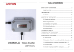
1
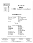
MIG240 MICRO INVERTER
INSTALLATION MANUAL
4J.JMIUL.03A
MIG240 MICRO INVERTER INSTALLATION MANUAL
FCC Compliance
This equipment has been tested and found to comply with the limits for a Class B digital device, pursuant to part 15
of the FCC Rules. These limits are designed to provide reasonable protection against harmful interference in a
residential installation. This equipment generates, uses and can radiate radio frequency energy and, if not installed
and used in accordance with the instructions, may cause harmful interference to radio communications. However,
there is no guarantee that interference will not occur in a particular installation. If this equipment does cause
harmful interference to radio or television reception, which can be determined by turning the equipment off and
on, you are encouraged to try to correct the interference by one or more of the following measures:
• Reorient or relocate the receiving antenna.
• Increase the separation between the equipment and the receiver.
• Connect the equipment into an outlet on a circuit different from that to which the receiver is connected.
• Consult the dealer or an experienced radio/TV technician for help.
Changes or modifications not expressly approved by the party responsible for compliance may void the user’s
authority to operate the equipment.
Other Information
Product information is subject to change without notice. All trademarks are recognized as the property of their
respective owners.
2|P a g e
©2013 Darfon America Corp.
Rev. 02
MIG240 MICRO INVERTER INSTALLATION MANUAL
TABLE OF CONTENTS
IMPORTANT SAFETY INSTRUCTIONS ............................................................................................4
ABOUT DARFON MICRO INVERTERS ............................................................................................5
General Overview ..........................................................................................................5
Advantages of Darfon Micro Inverters ............................................................................5
PRE-INSTALLATION ......................................................................................................................6
Layout PV System ...........................................................................................................6
Compatibility and Capacity .............................................................................................6
Parts and Tools ...............................................................................................................7
Lightning Surge Suppression ...........................................................................................7
Mounting Options ..........................................................................................................8
AC Trunk Cable ...............................................................................................................8
INSTALLATION PROCEDURE .........................................................................................................9
Installing onto a PV Racking System ................................................................................9
Installing onto the back of a PV Module ........................................................................ 12
POST-INSTALLATION .................................................................................................................. 15
Commissioning and Operating ...................................................................................... 15
Troubleshooting............................................................................................................ 15
Disconnecting a Micro Inverter ..................................................................................... 16
TECHNICAL SPECIFICATIONS ...................................................................................................... 17
INSTALLATION MAP ................................................................................................................... 18
SAMPLE WIRING DIAGRAM (Small system < 25 MIs) .................................................................. 19
SAMPLE WIRING DIAGRAM (Suggestion for small systems)........................................................ 20
SAMPLE WIRING DIAGRAM (Big system > 25 MIs)...................................................................... 21
LIMITED WARRANTY.................................................................................................................. 22
Rev. 02
©2013 Darfon America Corp.
3|P a g e
MIG240 MICRO INVERTER INSTALLATION MANUAL
IMPORTANT SAFETY INSTRUCTIONS
READ THIS FIRST & SAVE THESE INSTRUCTIONS.
This manual contains important instructions for the installation and maintenance of Darfon MIG240 micro
inverters. Before installing, please read these safety instructions carefully. Take special care to follow the warnings
indicated on the unit itself as well as the safety suggestion listed below.
Safety Symbols
To reduce the risk of injury and to ensure the continued safe operation of this product, the following safety
instructions and warnings are marked in this manual.
WARNING
This indicates the risk of electric shock. The presence of high voltage levels may constitute a risk of
injury or death to users and/or installers.
CAUTION
This indicates important information where failure to comply may result in safety hazards or cause
damage to this product.
!
Safety Instructions
•
•
•
•
•
•
•
•
•
•
•
•
•
•
Read all instructions and cautionary marks in the manual carefully before starting the installation.
Do not attempt to repair this product; it does not contain user-serviceable parts. Repairs and internal
servicing should only be performed by Darfon authorized service personnel.
Do not tamper with or open this product. Opening this product may result in electric shock.
Perform all electrical installations in accordance with all applicable local electrical codes and the National
Electrical Code (NEC), ANSI/NFPA 70.
Only qualified electrical personnel should perform the electrical installation and wiring of this product.
Be aware that even without an external voltage source connected, the MIG240 micro inverter may
contain high voltages and there is a risk of electrical shock.
Connect the Darfon micro inverter to the utility grid only after receiving prior approval from the electrical
utility company.
The temperature of the heat sinks outside of the device can reach over 85°C in normal operation. To
reduce risk of burns, use caution when working with micro inverters.
Do not disconnect the DC power source from the Darfon micro inverter without first disconnecting the AC
power source. Both AC and DC power sources must be disconnected before servicing. Be aware that DC
power/voltage is generated when the photovoltaic array is exposed to light.
Switch off the circuit breakers before installation and wirings.
For the safety of installation, remove all conductive jewelry or equipment during the installation or service
of the device parts, connector and/or wiring.
Do not stand on a wet location while doing installation and wirings. Enclose the outer covering well before
switch on the circuit breakers.
MIG240 inverters should be installed as instructed in this manual. Failure to comply with these
precautions or with specific warnings elsewhere in this manual violates safety standards of design,
manufacture, and intended use of the device. The manufacturer assumes no liability for the customer’s
failure to comply with these requirements.
When a GFDI (Ground fault) fault occurs, the LED will show sparking and alternating in orange and red.
Please refer to page 15 for more introductions.
4|P a g e
©2013 Darfon America Corp.
Rev. 02
MIG240 MICRO INVERTER INSTALLATION MANUAL
ABOUT DARFON MICRO INVERTERS
General Overview
Thank you for choosing Darfon’s MIG240 micro inverters as a key component to your solar power system. The
MIG240 converts DC power (generated by the solar module) to AC power (powers your home appliances). The
Darfon micro inverter is installed to the back of each solar module and connects to the electricity grid without the
need for a string or central inverter. The AC output from MIG240 micro inverter is synchronized and in-phase with
the electricity grid.
Advantages of Darfon Micro Inverters
Optimal Energy Harvest – Darfon’s micro inverters maximize the power produced from your Photovoltaic (PV)
array. This is accomplished by Maximum Power Point Tracking (MPPT), which monitors performance and
maximizes the power harvested from each solar module under varying environmental conditions. The
performance of an individual PV module may be affected by module mismatch, shading cause by trees or chimneys,
or obstruction from leaves or other debris. With MPPT, if the performance of an individual PV module is reduced, it
does not impact the performance of other PV modules in the array. This typically results in improved power
harvest of up to 20% from the solar PV system and represents a significant cost/performance advantage.
Improved Safety – Darfon micro inverters convert DC power to AC at each solar module; thus, eliminating the
need for high voltage DC wiring and making the solar system intrinsically safer. By eliminating DC wiring,
specialized DC practices and equipment are not required for installation.
Increased Lifetime and Reliability – Darfon micro inverters are more reliable and have a longer life cycle than the
traditional string or central inverters. Typically, string/central inverters will need to be replaced at least once over
the lifetime of the solar module adding significantly to the overall cost of the solar PV system. Darfon’s solar micro
inverters are designed to operate in real world conditions and achieve a peak efficiency of 95.7% for temperatures
between -40°C (-40°F) and 65°C (150°F) without degradation of performance. The micro inverter housing is
designed for outdoor installation and complies with the NEMA 6 environmental enclosure rating standard.
Enhanced Monitoring System – Darfon’s enhanced monitoring system can view the performance of each module
in the PV array, a capability not available with string inverters. This provides users/installers with detailed real-time
information that can be used to pinpoint the location of performance issues and provide guidance for maintenance,
ensuring the solar system’s performance is optimized over the lifetime of the installation.
Simplified PV Array Design and Installation – With Darfon micro inverters, the PV array design and installation can
be simplified because solar modules can be installed on any available space on rooftops. With conventional
inverters, the PV array design and installation are generally more complicated due to the effects shading has on
the overall performance of the PV array. When using Darfon micro inverters, installers do not need to match the
performance levels of adjacent solar modules to optimize the performance, making solar installations easier, faster
and cheaper to implement.
Rev. 02
©2013 Darfon America Corp.
5|P a g e
MIG240 MICRO INVERTER INSTALLATION MANUAL
PRE-INSTALLATION
Review and follow the instructions in this section before installing Darfon MIG240 micro inverters.
Layout PV System
The PV system layout will need to be planned before installation. The layout/plan will affect the wiring and cabling
schemes, and it will need to be adjusted accordingly. The layout will also need to account for the constraints of the
distance between each PV module due to the cable length.
Compatibility and Capacity
Darfon MIG240 micro inverters are electrically compatible with PV modules that have a voltage range of 24V~40V
and a maximum wattage of 260W. For more information, refer to the Technical Specifications section on page 18.
For a list of electrically-compatible PV modules and racking systems, refer to the Darfon website at
www.darfonsolar.com. Before ordering the PV module connector, make sure the connector type is compatible
with both the micro inverter and PV module
Electrical Compatibility
Model
PV MPPT Voltage Range PV Module Connector Type
MIG240
24V~40V
MC-4 Locking, Tyco Solarlock Locking, or Amphenol H4 Locking DC
Voltage and Capacity
Maximum number of MIG240s per AC Branch Circuit
Overcurrent Protection
240V with 10AWG AC Trunk Cable
25
30Amp Breaker
240V with 12AWG AC Trunk Cable
17
20Amp Breaker
WARNING
DO NOT exceed the maximum number of micro inverters in an AC branch circuit as listed above.
!
6|P a g e
CAUTION
Each AC branch circuit must be protected by a dedicated circuit breaker of 30A or less if using 10
AWG trunk cable, or 20A or less if using 12 AWG trunk cable.
©2013 Darfon America Corp.
Rev. 02
MIG240 MICRO INVERTER INSTALLATION MANUAL
Parts and Tools
This section provides a list of equipment and tools needed for installing and setting up the PV system.
Darfon Equipment
• MIG240 micro inverter
• AC trunk cables (with T-branch connectors)
• Sealing caps (for any unused drops on the AC trunk cable)
• Terminators (one needed at the end of each AC branch circuit)
Other Equipment/Tools
• PV module
• PV racking (with a DC junction box attached to one of its ends)
• Cable clips or tie wraps
• AC junction boxes
• Gland or strain relief fitting (one per AC junction box)
• Continuous grounding conductor, grounding washers
• Torque wrench, sockets, wrenches for mounting hardware
• Adjustable wrench or open-ended wrench (for terminators)
Lightning Surge Suppression
Lightning does not actually need to strike the equipment or building where the PV system is installed to cause
damage. Often, a strike nearby will induce voltage spikes in the electrical grid that can damage equipment.
Darfon’s micro inverters (MIG240) have built-in integral surge protection, much higher than most traditional
inverters. However, if the surge has sufficient energy, the built- in protection in the device would exceed, and the
device can be damaged.
As the Darfon Limited Warranty does not cover “extraordinary and unexpected manifestation of the forces
of nature,” such as lightning strikes, it is recommended to install surge protection as part of any solar installation.
We recommend the following protection devices. These have been tested to ensure that they do not interfere with
power line communications. Install per vendor instructions.
Residential:
Vendor: Citel, Part Number DS72RS-120 or DS73RS-120
Application: DS72RS-120 is applied when N-G is bound together, or DS73RS-120 were N-G is unbound.
Commercial:
Vendor: Citel, Part Number SP-120
Application: Branch panel protection
See the vendor datasheet for DS70R, (which includes the DS72RS-120) or for SP-120 at
www.citelprotection.com/english/citel_data_sheets/ac_protection/
Rev. 02
©2013 Darfon America Corp.
7|P a g e
MIG240 MICRO INVERTER INSTALLATION MANUAL
Mounting Options
The micro inverter can be mounted and installed on the back of the PV module panel (screw-tightened to the
frame of the panel) or on the standard PV racking. The micro inverter will vary based on the type of mounting
option chosen. Be sure to have the correct micro inverters to support the installation type.
Option 1: Mounting onto the PV Racking
Option 2: Mounting onto the Back of the PV Module
AC Trunk Cable
There are different types and options for AC trunk cables. Depending on the orientation of the installation, the AC
trunk cable can be in portrait or landscape format. Trunk cables can also consist of three pins (three wires) or four
pins (four wires). Darfon currently uses the four-pin AC trunk cable.
1
4
2
3
Pin
1
2
3
4
Wire Color
Black
Red
Green
White
Wire Usage
L1
L2
Ground
Neutral
Note: Darfon previously used the three-pin AC trunk cable. For support, please contact an authorized Darfon
representative.
3
2
8|P a g e
1
Pin
1
2
3
Wire Color
Black
White
Green
Wire Usage
L1
L2
Ground
©2013 Darfon America Corp.
Rev. 02
MIG240 MICRO INVERTER INSTALLATION MANUAL
INSTALLATION PROCEDURE
The following sections list steps on how to install the micro inverter on
onto a standard PV racking or onto
on the back of
a PV module. Ensure the micro inverter matches the installation method (Refer
(Refer to the Mounting Options section on
page 6). Before installing, review
eview and follow all important safety instructions listed at the beginning of this manual.
Installing onto a PV Racking System
Step 1: Measure AC Service at the Site
Measure service entrance conductors to confirm AC
service at the site. Verify that the AC voltages at the
electrical utility connection and at the junction box for
each AC branch circuit are within the ranges.
240 Volt AC Single Phase
L1 to L2
211 to 264 VAC
L1, L2 to neutral
106 to 132 VAC
Step 2: Install the AC Branch Circuit Junction Box
2.1 Mount the adapter plate to a suitable location on
the PV racking system (typically at the end of a row
of modules). The adapter plate must be installed
with an appropriate junction box.
2.2 Connect the open wire end of the AC interconnect
cable into
to the junction box using an appropriate
gland or strain relief fitting. The AC interconnect
cable requires a strain relief connector with an
opening of 3/8 inches in diameter.
Step 3: Lay Out the AC Trunk Cable
Place the AC trunk cable at the required location. Align the Tbranch connector to the position where the micro inverter
will be installed. Then secure the cable on either side of the
rack using cable clips or tie wraps.
Step 4: Attach the Micro Inverter to the PV Racking
4.1 Note the approximate centers of each PV module
on the PV racking.
4.2 Evaluate the location of the micro inverter against
potential collection of moisture or water.
4.3 Evaluate the location of the micro inverter with
respect to the DC junction box and the PV mod
module
frame.
4.4 Align the MIG240 so that the holes on the mounting
bracket are above the slot opening on the PV
racking and secure the micro inverter to the PV
racking with screws.
!
Rev. 02
CAUTION
Ensure that the inverter does not obstruct the PV module frame or stiffen braces.
Ensure the micro inverter’s AC connector can easily reach the TT-branch
branch connector.
©2013 Darfon America Corp.
9|P a g e
MIG240 MICRO INVERTER INSTALLATION MANUAL
Step 5: Ground the Micro Inverters
Unscrew the top of grounding clips on the micro inverters. Run the grounding electrode conductor to each
grounding clip on the micro inverter and then to the junction box. After laying out the grounding conductor, secure
the top of the grounding clips back onto the micro inverters.
WARNING
Correct AC grounding and short circuit protection must be provided to ens
ensure
ure operational safety.
Step 6: Connect the Micro Inverters
6.1 Remove the temporary shipping cap from the tt-branch
branch on the AC trunk cable and connect the micro
inverter. Ensure the connection is secure and locked into place. (Depending on the trunk cable’s
manufacturer, the locking mechanism will vary.)
6.2 Repeat for all micro inverters in the AC branch circuit.
6.3 For any unused connectors on the AC trunk cable, replace the temporary shipping cap with a sealing cap.
Listen for a click as the sealing cap is connected to ensure that it is securely locked into place.
10 | P a g e
©2013 Darfon America Corp.
Rev. 02
MIG240 MICRO INVERTER INSTALLATION MANUAL
Step 7: Terminate the Unused End of the AC Trunk Cable
7.1 Strip 10mm (about 0.5in) of the outer sheath from the end of the AC trunk cable.
7.2 Each terminator has four parts: the sealing nut, clamp ring, seal and cap. Slide the sealing nut, clamp ring
and then the seal onto the AC trunk cable.
7.3 Insert the individual wires into the slots inside the cap of the terminator.
7.4 Screw the hex nut onto the cap. Use a wrench to ensure the hex nut is screwed in all the way to the base
of the cap.
WARNING
Ensure the AC trunk cable and terminator do not touch the roof by using cable clips or tie wraps to
attach the trunk cable to the PV racking. Ensure that all cabling is located underneath the PV module.
Step 8: Connect the AC Junction Box
Connect the AC trunk cable to the AC junction box using the appropriate gland or strain relief fitting. The AC trunk
cable requires a strain relief connector with an opening of 1.6 cm (0.6 in) in diameter.
The wires in the AC trunk cable are identified by color: L1 is sheathed in Black, L2 is sheathed in Red, Neutral is
sheathed in White and Ground is sheathed in Green.
WARNING
Although the AC trunk cable includes a grounding wire, the continuous grounding conductor or
grounding washers is still required.
Step 9: Connect the PV Modules
Mount the PV modules above the micro inverters, and then connect each micro inverter to a PV module. (The
micro inverter and PV module’s DC cables have two connectors. Connect the micro inverter positive connector to
the PV module negative connector, and vice versa.)
!
CAUTION
Micro inverters and PV modules are installed using a one to one ratio.
Step 10: Connect Monitoring System (Optional)
The monitoring system requires additional equipment (PLC box and data logger). For more information on the
monitoring system, refer to the PV Monitoring System user’s manual.
Rev. 02
©2013 Darfon America Corp.
11 | P a g e
MIG240 MICRO INVERTER INSTALLATION MANUAL
Installing onto the back of a PV Module
Step 1: Measure AC Service at the Site
Measure service entrance conductors to confirm AC
service at the site. Verify that the AC voltages at the
electrical utility connection and at the junction box for
each AC branch circuit are within the ranges.
240 Volt AC Single Phase
L1 to L2
211 to 264 VAC
L1, L2 to neutral
106 to 132 VAC
Step 2: Attach the micro inverter to the PV module.
2.1 Using the micro inverter as a reference, mark the
location on PV module frame where it needs to be
drilled.
2.2 Drill the holes into the PV module frame using M5.5
drill bit.
2.3 Insert the M4 support bolts (x3). Note: Each M4
support bolt has adhesive to secure it to the PV
module frame. Be sure to remove the liner from the
adhesive before inserting the bolts.
2.4 Place the micro inverter onto the PV module and
secure it to the M4 bolts.
Step 3: Connect the PV modules.
Connect the micro inverter DC cable to the PV module’s DC cable. (The micro inverter and PV module’s DC cables
have two connectors. Connect the micro inverter positive connector to the PV module negative connector, and
vice versa.)
!
12 | P a g e
CAUTION
Micro inverters and PV modules are installed using a one to one ratio.
©2013 Darfon America Corp.
Rev. 02
MIG240 MICRO INVERTER INSTALLATION MANUAL
Step 4: Install the AC Branch Circuit Junction Box
4.1 Mount the adapter plate to a suitable location
on the PV racking system (typically at the end
of a row of modules). The adapter plate must
be installed with an appropriate junction box.
4.1 Connect the open wire end of the AC
interconnect cable into the junction box using
an appropriate gland or strain relief fitting. The
AC interconnect cable requires a strain relief
connector with an opening of 3/8 inches in
diameter.
Step 5: Lay Out the AC Trunk Cable.
Place the AC trunk cable at the required location. Align the T-branch connector to the position where the micro
inverter will be installed. Then secure the cable on either side of the rack using cable clips or tie wraps.
Step 6: Terminate the Unused End of the AC Trunk Cable
6.1 Strip 10mm (about 0.5in) of the outer sheath from the end of the AC trunk cable.
6.2 Each terminator has four parts: the sealing nut, clamp ring, seal and cap. Slide the sealing nut, clamp ring
and then the seal onto the AC trunk cable.
6.3 Insert the individual wires into the slots inside the cap of the terminator.
6.4 Screw the hex nut onto the cap. Use a wrench to ensure the hex nut is screwed in all the way to the base
of the cap.
WARNING
Ensure the AC trunk cable and terminator do not touch the roof by using cable clips or tie wraps to
attach the AC trunk cable to the PV racking. Ensure that all cabling is located underneath the PV
module.
Step 7: Place the PV Module on to the PV Racking.
Step 8: Ground the Micro Inverters
Unscrew the top of grounding clips on the micro inverters. Run the grounding electrode conductor to each
grounding clip on the micro inverter and then to the junction box. After laying out the grounding conductor, secure
the top of the grounding clips back onto the micro inverters.
WARNING
Correct AC grounding and short circuit protection must be provided to ensure operational safety.
Rev. 02
©2013 Darfon America Corp.
13 | P a g e
MIG240 MICRO INVERTER INSTALLATION MANUAL
Step 9: Connect the Micro Inverters to the AC Trunk.
9.1 Remove the temporary shipping cap from the t-branch on the AC trunk cable and connect the micro
inverter. Ensure the connection is secure and locked into place. (Depending on the trunk cable’s
manufacturer, the locking mechanism will vary.)
9.2 Repeat for all micro inverters in the AC branch circuit.
9.3 For any unused connectors on the AC trunk cable, replace the temporary shipping cap with a sealing cap.
Listen for a click as the sealing cap is connected to ensure that it is securely locked into place.
Step 10: Connect the AC Junction Box
Connect the AC trunk cable to the AC junction box using the appropriate gland or strain relief fitting. The AC trunk
cable requires a strain relief connector with an opening of 1.6 cm (0.6 in) in diameter.
The wires in the AC trunk cable are identified by color: L1 is sheathed in Black, L2 is sheathed in Red, Neutral is
sheathed in White and Ground is sheathed in Green.
WARNING
Although the AC trunk cable includes a grounding wire, the continuous grounding conductor or
grounding washers is still required.
Step 11: Connect Monitoring System (Optional)
The monitoring system requires additional equipment (PLC box and data logger). For more information on the
monitoring system, refer to the PV Monitoring System user’s manual.
14 | P a g e
©2013 Darfon America Corp.
Rev. 02
MIG240 MICRO INVERTER INSTALLATION MANUAL
POST-INSTALLATION
WARNING
Changes to your electrical system should be carried out only by qualified electricians.
WARNING
Do not attempt to repair this product; it does not contain user-serviceable parts. Repairs and internal
servicing should only be performed by Darfon authorized service personnel.
Commissioning and Operating
Step 1: Turn on the AC disconnect of the circuit breaker from each micro inverter AC branch circuit.
Step 2: Turn on the main utility-grid AC circuit breaker. Your system will start producing power after five minutes.
Step 3: (Optional Monitoring System) Depending on the strength of the signal, it can take up to 2 hours before the
monitoring system detect all the micro inverters in the PV system. For more information on the monitoring
system, refer to the PV Monitoring System user’s manual.
GFDI fault
GFDI fault means there are current between panel and ground, and that may damage the panel or strike people
who touch the panel or the solar system. When a GFDI (Ground fault) fault occurs, the LED will show sparking and
alternating in orange and red, and MIG240 will disconnect the system to prevent people to get strike.
When GFDI occur, please contact with the installer and follow the Operation Manual to clear this condition. Or you
can contack with Darfon customer support at [email protected].
Troubleshooting
If the PV system is not operating correctly, use the steps in this section to troubleshoot the problem. If the issue
cannot be corrected using the steps in this section, please contact a Darfon authorized service personnel.
LED Indicators
LED Status
Depending on the position/location of the
installed micro inverter, the use of handheld
mirrors may be needed. If the micro inverter’s
LED indicator is not showing a color or is
flashing red, follow these steps.
Step 1: Verify that the AC voltage and
frequency in the connection to the
utility grid are in the appropriate
ranges. Ranges are in the Technical
Specifications section on page 18.
Step 2: Verify that the AC voltages at the electrical
utility connection and at the junction box for
each AC branch circuit are within the ranges.
Rev. 02
Description
Flashing Orange
Normal Start-up Operation
Solid Orange
Minimum Start Voltage Met
Solid Green
Operating - MPPT/Grid Mode On
Flashing Green
Operating - Over Maximum Wattage
Solid Red
Not Operating - Low Voltage
Flashing Red (0.5 Hz) Restarting - Minimum Voltage Met
Flashing Red (2 Hz)
Halt Manually/Calibration or
Flash Programming
240 Volt AC Single Phase
L1 to L2
211 to 264 VAC
L1, L2 to neutral
106 to 132 VAC
©2013 Darfon America Corp.
15 | P a g e
MIG240 MICRO INVERTER INSTALLATION MANUAL
Step 3: Verify that there is AC voltage from the AC branch circuit to each micro inverter.
Step 4: Verify that any upstream AC disconnects, as well as the dedicated circuit breakers for each AC branch
circuit, are functioning properly and are closed.
Step 5: Verify the PV module DC voltage is within the allowable voltage and wattage range shown in the Technical
Specifications section on page 25.
Step 6: Verify the DC is connected correctly between the micro inverter and the PV module.
Step 7: If the problem persists, contact Darfon Technical Support at [email protected].
Disconnecting a Micro Inverter
Ensure the micro inverter is not disconnected from the PV modules under load and switch off the circuit breakers.
Step 1: Disconnect the micro inverter from the AC trunk cable.
Step 2: Completely cover the PV module with an opaque cover.
WARNING
Be aware that DC power/voltage is generated when the PV module is exposed to light.
Step 3: Using a meter, verify that the DC wires between the PV module and the micro inverter does not have a
current.
Step 4: Disconnect the PV module from the micro inverter. To disconnect the micro inverter’s positive connector,
squeeze the locking mechanism and pull the connectors apart. The micro inverter’s negative connector is
tool-removable only.
Positive Connector
Negative Connector
Step 5: Disconnect the grounding wire or washer from the micro inverter.
Step 6: Remove the micro inverter from the PV racking.
16 | P a g e
©2013 Darfon America Corp.
Rev. 02
MIG240 MICRO INVERTER INSTALLATION MANUAL
WARNING
Do not leave the T-branch connector on the AC trunk cable exposed for an extended period of time. If
the removed micro inverter will not be replaced with another micro inverter immediately, connect a
sealing cap to the T-branch connector.
Rev. 02
©2013 Darfon America Corp.
17 | P a g e
MIG240 MICRO INVERTER INSTALLATION MANUAL
TECHNICAL SPECIFICATIONS
MIG240UL00
Input Data (DC)
Recommended Maximum Input Power (STC)
Up to 260W
Nominal Input Power
240W
Maximum Input DC Voltage
60V
Maximum Peak Power Tracking Voltage
24 ~ 40V
Minimum Start Voltage
24V
Maximum DC Short Circuit Current
12A
Maximum Input Current
10A
Output Data (AC)
Maximum Continuous Output Power
220W
Maximum Peak Output Power
245W
Nominal Output Current
0.917A
Nominal Voltage / Range
240 / 211-264 V
Nominal Frequency / Range
60 / 59.3-60.5 Hz *
Power Factor
>0.95
Maximum Units per 30A Branch Circuit
25 (Single Phase)
Efficiency
Peak Inverter Efficiency
95.7%
CEC Weighted Efficiency
95%
Nominal MPP Tracking
99%
Night Time Power Consumption
51mW
Mechanical Data
Ambient Temperature Range
-40°C to 65°C
Operating Temperature Range (Internal)
-40°C to 85°C
Dimensions (WxHxD)
8.7 x 5.1 x 1.5 in (220 x 130 x 37mm)
Weight
5.5 lbs (2.5 kg)
Cooling
Natural Convention - No Fans
Enclosure Environmental Rating
Outdoor - NEMA 6
Features
Communication
Powerline
EN 61000-6-2, EN 61000-6-3,FCC Part15 Class B,
UL 1741, IEEE 1547
Compliance
* Extended frequency range available to serve local markets.
18 | P a g e
©2013 Darfon America Corp.
Rev. 02
Rev. 02
©2013 Darfon America Corp.
m
l
k
j
i
h
g
f
e
d
c
b
a
A
B
Customer Information
Installer Information
C
D
E
Site: _____________
Azimuth: __________
Date: _____________
F
G
H
Please print this page.
Sheet ______ of ______
MIG240 MICRO INVERTER INSTALLATION MANUAL
DARFON MICRO INVERTER INSTALLATION MAP
19 | P a g e
MIG240 MICRO INVERTER INSTALLATION MANUAL
SAMPLE WIRING DIAGRAM (Small system < 25 MIs)
240 VAC, single phase with monitoring system
20 | P a g e
©2013 Darfon America Corp.
Rev. 02
MIG240 MICRO INVERTER INSTALLATION MANUAL
SAMPLE WIRING DIAGRAM (communication
communication system installation)
installation
If the system is less than 25 MIs as below in the figure, Darfon suggests putting the PLC Box in the center
of the strings to improve communication.
Rev. 02
©2013 Darfon America Corp.
21 | P a g e
References for the layout on the roof.
Rule 1: One PLC can support to 25 units of MIG240 maximum.(No more than 13 units each in each side.)
Rule 2: Don't put PLC Box closed to each other, that means users need to put PLC btw Mis strings.
4J.JMIUL.03A
MIG240 MICRO INVERTER INSTALLATION MANUAL
Rule 3: Keep PLC closed to the microinverters. (No more than 10 m from the first
unit)
Rule 4: Commercial layout should be regular and arranged.
Rev. 02
©2013 Darfon America Corp.
23 | P a g e
MIG240 MICRO INVERTER INSTALLATION MANUAL
[Data logger] Internet setting (AT&T router as an example)
This is a real hard one to find anything out about. Even Motorola doesn't have anything
on their site dealing with this specific model, and that could be because either AT&T has
them specifically make this model for them, or because Motorola split into two
companies and stuff isn't all updated/transferred yet.
As Darfon don't have one of these, and all equipment isn't the same, Darfon will give
you what we have found. The previous Motorolas in AT&T/SBC areas was the
2210/2310, which evolved somehow into the Netopia lines or was based on them.
There is a PDF manual for these models, and this embedded link (opens in new
tab/window ) will open it. Go to page 14, get into the router, then go to page43.
(if the embedded link is not working, please refer to address as below,
http://www1.arrisi.com/staticfiles/Support/US-EN/Home-and-Office/DSL-Modems-andGateways/2210-02-10NA-ADSL2-Residential-Gatewayy/Documents/Static-Files/221002-10NA_AdminHandbook_v784.pdf)
Step 0:
Run a Web browser, such as Mozilla Firefox or Microsoft Internet Explorer.
Enter http://192.168.1.254 in the URL Address text box.
The user name/password: should be admin/admin. Otherwise, you have to contact with
the ISP.
24 | P a g e
©2013 Darfon America Corp.
Rev. 02
MIG240 MICRO INVERTER INSTALLATION MANUAL
Step1:
Key-in the service name as “data logger”. Once you choose a software service or game, click
Enable.
Data logger
Step 2:
Key-in the IP address on display of data logger. Then Enable.
Step 3:
Define customer service as “Port Forwarding”.
Rev. 02
©2013 Darfon America Corp.
25 | P a g e
MIG240 MICRO INVERTER INSTALLATION MANUAL
Data logger
Step 4:
Set the port to be 21, and Click the Next button.
Data logger
80
80
80
Step 5:
26 | P a g e
©2013 Darfon America Corp.
Rev. 02
MIG240 MICRO INVERTER INSTALLATION MANUAL
Repeat Step 1 ~ 4, you can make service name as xxxx.1, xxxx.2, and set the prot as 23 and 80
as below.
Data logger.1
21
21
21
Data logger.2
23
23
23
Use those instructions as a guide if it's somewhat similar.
Rev. 02
©2013 Darfon America Corp.
27 | P a g e
MIG240 MICRO INVERTER INSTALLATION MANUAL
Time server Setting manual
Step 1 Login the system
The default ID is user, default Password is user
Step 2 Select “Other”
28 | P a g e
©2013 Darfon America Corp.
Rev. 02
MIG240 MICRO INVERTER INSTALLATION MANUAL
Step 3 Key in Time server
Default Time Server is 220.130.158.71
Step 4 Key in GMT
Default GMT is Taipei
Refer Time zone reference city table input matches the time zone of the city name
(Please note that the bottom line and lower case letters)
Rev. 02
©2013 Darfon America Corp.
29 | P a g e
MIG240 MICRO INVERTER INSTALLATION MANUAL
Time zone reference city table (UTC)
30 | P a g e
©2013 Darfon America Corp.
Rev. 02
MIG240 MICRO INVERTER INSTALLATION MANUAL
Rev. 02
©2013 Darfon America Corp.
31 | P a g e
MIG240 MICRO INVERTER INSTALLATION MANUAL
Manufactured by:
Darfon Electronics Corp.
167 Shan-ying Road, Gueishan,
Taoyuan 333, Taiwan, (R.O.C.)
Tel: +886 3 2508800
www.darfon.com
US Office:
Darfon America Corp.
3031 Tisch Way, Suite 610
San Jose, CA 95128
Tel: +1 408 260 3880
32 | P a g e
©2013 Darfon America Corp.
Rev. 02