1
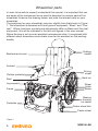
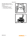
USER MANUAL
EN
MB3160-EN-C
Introduction
Congratulations on your choice of new wheelchair
Quality and function are key aspects of all wheelchairs in the Handicare series.
For your own safety, and in order for you to get the best possible benefit from the
features of your new wheelchair, we recommend that you read this user manual
carefully before you start to use the wheelchair.
Emineo in brief
Emineo has been developed in line with the market. The result is a wheelchair
with particularly good seating comfort through its unique tilt function and newly
developed back solution.
Emineo is an extremely light wheelchair, it rolls easily and has a narrow seat, which
provides good capabilities for negotiating obstacles through narrow doors and in
narrow rooms.
By means of its extensive accessories programme, Emineo can easily be adapted
to each user. Many different adjustments can be made and the adjusting procedures
are intuitive and demand minimum use of tools and replacement of parts. Measuring
scales on all adjustment points simplify the adjustments and ensure their accuracy.
www.handicare.com
2
MB3160-EN
Contents
Introduction...................................................................................2
Contents ........................................................................................3
Wheelchair parts ..........................................................................4
Assembly .......................................................................................5
Using the wheelchair....................................................................6
Hip belt ........................................................................................28
Safety ...........................................................................................29
Safety in cars ..............................................................................31
Maintenance ...............................................................................34
Labelling ......................................................................................37
Technical specifications ............................................................38
Accessories ................................................................................40
Guarantee....................................................................................42
MB3160-EN
3
Wheelchair parts
In order to be able to properly understand this manual, it is important that you
are aware of the commonest terms used to describe the various parts of the
wheelchair. Examine the drawing below, and note the relevant parts on your
wheelchair.
The equipment on your wheelchair may vary slightly from that shown in Figure
1. The wheelchair is delivered with two types of equipment; “Basic” and “Onetool”. Where functions, controls and adjustments differ on Basic and One-tool
equipment, this will be indicated in the text and figures in this user manual.
Where Emineo is set up as an assistant-manoeuvred chair, it is equipped with
different wheel dimensions and a brake lever for the assistant on the pushing
handle.
Backrest and cover
Pushing
handle
Armrest
Clothes protector
Seat
Leg support
Frame
Footplate
Driving
wheel
Hand rim
Wheel
block
Brake
Bearing
housing
for castor
Castor wheel fork
Castor wheel
Figure 1
4
MB3160-EN
Assembly
Assembly Figures 2 and 3
The standard wheelchair is delivered
complete.
All you need to do is:
• Unfold the back, see page 12
• Fit the armrests, see page 6
• Fit the leg supports, see page 7
Figure 2
Figure 3
MB3160-EN
5
Using the wheelchair
Quick-release catch Figure 4
The wheelchair has a quick-release catch
on the driving wheels. Press the button in
the middle of the driving wheel in order to
remove or attach the wheel.
NB!
Check that the wheel is properly secured
by ensuring that the button pops out
approximately 5 mm when the wheel bolt
is completely in the casing.
Figure 4
Height adjustable pushing handle
Figure 5
The pushing handle is adjusted by
loosening the locking handle (5A) whilst
moving the pushing handle upwards or
downwards to the desired height. Retighten the locking handle.
For extra safety, the pushing handle is
fitted with a snap lock in the uppermost
position. To remove the pushing handle,
pull it up to the uppermost position and
press the snap lock (5B).
B
A
Figure 5
Armrests, removing and fitting
Figure 6
Remove the armrests by lifting them up.
To fit them back on, place them in the
armrest tubing.
Figure 6
6
MB3160-EN
Using the wheelchair
Swing out/attach/remove the leg
supports Figures 7 and 8
The procedure is the same for fixed and
angle adjustable leg supports.
The leg supports can be swung in/out or
removed in order to make transport and
getting in and out of the chair easier. The
leg supports can be released by twisting
the lever (7A) inwards or outwards whilst
swinging the leg supports.
After the leg support has been swung to
the side, it can be lifted straight up and
completely removed if desired. In order
to attach it again, carry out these steps
in reverse order, and the handle will lock
automatically.
A
Figure 7
The complete leg support unit and
fastenings can be removed, see page 27.
Figure 8
MB3160-EN
7
Using the wheelchair
Using the brakes Figure 9
Pull the brake lever towards you to
engage the brake.
The brake is only designed to hold
the chair when it is stationary. Under
no circumstances should it be used
as a driving brake.
Figure 9
To make sideways transfer easier, the
brake lever can be folded down. This is
done by pulling the brake lever upwards
and then folding it down.
Using the brakes on Emineo
with assistant brake Figure 10
(assistant brake is standard on helperguided chairs; also available as an
accessory)
• Squeeze the brake handles (18A) to
brake
• Push the release handle (10B) away
from you to lock the brakes on when
parking. Squeeze the release handle
to release the brakes
A
B
Figure 10
8
MB3160-EN
Using the wheelchair
Anti-tip stabiliser/tipping bar
Figure 11 and 12
The anti-tip stabiliser is put into position
by pulling it out and turning it in a
downward direction simultaneously. The
anti-tip stabiliser is adjusted as standard
with a clearance to the base that makes it
possible to mount doorsteps etc.
The tipping bar is accessible when the
anti-tip stabiliser is up or down.
One-tool
Figure 11
Basic
Figure 12
MB3160-EN
9
Using the wheelchair
Tilting Figure 13
When you tilt the chair, the balance
point is retained. As you tilt the chair
backwards, the back opens 8°. You can
use various methods for tilting the chair
depending on your function level:
• The assistant squeezes the tilt lever
and the user leans forward/backward
• The assistant squeezes the tilt lever
and the user pulls himself forward/
pushes himself backward using his
hands
Figure 13
Beware of pinching
If a table has been fitted to the Emineo,
the chair must not be tilted with the user
in it.
Beware of pinching!
A user-controlled tilt lever which the user
can use without the help of an assistant, is
available as an accessory.
The balance point on Emineo can be
adjusted for optimal use in relation to the
user’s function level and weight. See page
22.
10
Do not put hands etc. between
the side frame and leg support
attachments when tilting the
wheelchair.
MB3160-EN
Using the wheelchair
Adjusting the back angle using
the adjustment lever (accessory)
Figure 14
Adjust the back angle separately using
the lever (14A).
• Squeeze the lever as you push the
backrest forwards or backwards
A
Figure 14
Electrical tilt and back
(accessory)
Use the manual control to tilt the chair and
change the back angle.
Charge procedure
Figure 15
The wheelchair must not be used during
charging. Only charge the chair when it is
not in use.
Place the charger plug in the manual
control and connect to electricity (230
V). A green light will show on the charger
when the batteries are fully charged.
MB3160-EN
11
Using the wheelchair
Fold the backrest up or down
Figures 16 and 17
• Remove the armrests
• Tilt the chair forwards. Pull out the bolt
(16A) and turn it 90° to lock it in the
open position, release the bolt and fold
down the back
A
Carry out this procedure in reverse order
to pull the back up.
Figure 16
Figure 17
12
MB3160-EN
Using the wheelchair
Moving in and out of the chair
Figures 18, 19 and 20
• Activate the brakes
• Swing out or remove the leg supports
• Tilt the chair forwards
• The user can now be moved in or out
the wheelchair by means of manual
lifting or a person lift, or frontal
movement if the user has the ability to
stand, see figures 18, 19 and 20
Figure 18
Figure 19
Figure 20
MB3160-EN
13
Using the wheelchair
Negotiating obstacles, stairs
Figures 21 and 22
If the wheelchair is being lifted up/
down stairs with the user sitting in it, the
recommended lifting points should be
used. These are marked on the product.
The lifting points
are the pushing
handle and the
leg supports.
Figure 21
Do not lift the wheelchair by the
armrests. Do not lift the wheelchair
by angle adjustable leg supports.
NB!
Make sure that the pushing handle is
locked before lifting.
In order for assistants to have a better
lifting position, they can alternatively lift
from each side of the wheelchair.
Figure 22
Negotiating obstacles, kerbs
Figure 23
When negotiating kerbs etc., swing the
anti-tip stabiliser up. Then place one foot
on the tipping bar whilst steering with the
pushing handle. Tilt the chair backwards
where necessary to get clearance between
the obstacle and leg supports.
Steep terrain
For frequent use in undulating terrain, we
recommend that a separate brake is fitted
for an assistant where relevant.
Figure 23
14
MB3160-EN
Adjusting the wheelchair
Adjusting the seat height
The seat height can easily be adjusted.
The different ways of adjusting the seat
height also affect the ability to negotiate
obstacles and rolling properties of the
wheelchair.
NB!
Do not adjust Emineo so that you have
different seat heights at the front and
back, as this can affect the balance point.
Adjusting the seat height – back
Figure 24
Figure 24
The seat height at the back can be
adjusted using the methods below.
Moving the wheel block up or down
Moving the wheel block up lowers the
seat. Moving the wheel block down raises
the seat. See page 17.
Changing to bigger or smaller driving
wheels
A bigger driving wheel increases the seat
height, whilst a smaller wheel decreases
the height. The table on page 38 shows
which seat heights can be achieved by
changing to different sizes of driving
wheel.
Adjusting the seat height – front
Figure 24
The seat height at the front can be
adjusted using the methods below. The
table on page 38 shows which seat
heights can be achieved by using the
different methods.
MB3160-EN
15
Adjusting the wheelchair
• Move the bearing housing of the castor
wheel up or down (One-tool)
(see page 19)
Moving the bearing housing up lowers
the seat, and moving it down raises
the seat.
• Move the castor wheel to a higher or
lower position in the castor wheel fork
Moving the castor wheel to a higher
position in the castor wheel fork (25A)
lowers the seat, and moving the castor
wheel to a lower position raises the
seat.
Castor wheel fork
Bearing
housing
A
Castor
wheel
Figure 25
• Changing to bigger or smaller castor
wheels
A smaller castor wheel reduces the
seat height, whilst a bigger castor
wheel increases the seat height. By
changing the castor wheel, a smaller
castor wheel will give a smaller turning
radius, and thereby increase the ability
to negotiate obstacles in narrow
spaces, and will also give more room
for the legs. A larger castor wheel will
increase the turning radius but will
also improve the ability to negotiate
obstacles on uneven surfaces.
• Changing to a longer or shorter castor
wheel fork
A shorter castor wheel fork reduces
the seat height, gives a smaller turning
radius, and thereby increases the
ability to negotiate obstacles in narrow
spaces, and will also give more room
for the legs. A longer castor wheel fork
increases the seat height, and allows
several alternative castor wheels to be
used.
16
NB! Remember to adjust the
angle of the castor wheel when
you change the seat height.
Remember also to adjust the
brakes when adjusting the seat
height at the back.
MB3160-EN
Adjusting the wheelchair
Adjusting the seat height – back
(One-tool) Figures 26 and 27
On the wheelchair frame you will find a
measuring scale (27A), which shows the
seat height in relation to the size of the
driving wheel.
• Remove the driving wheel
• Loosen the nut (27B) using a 29 mm
wrench and unscrew until it stops
• Pull the inner and outer wheel block
slightly apart
• Adjust the wheel block step-by-step up
or down in accordance with the scale
• Squeeze the inner and outer wheel
block together
Figure 26
A
NB!
• It is important to ensure that the pins
in the wheel block go into the holes
in the frame and that the casing
lies horizontally in the track before
tightening
20
35
38
37
39
1,5
44 4
41
3,5
46 4
B
43
5,5
48 4
Figure 27
Seat heights that
can be achieved
by the different
steps on the scale
Find the dimension of your driving
wheel at the top of the scale. The
column under the wheel dimension
shows where to place the wheel
block in order to achieve the various
seat heights.
Alternative driving
wheel dimensions
MB3160-EN
17
Adjusting the wheelchair
Adjusting the seat height – back
(Basic) Figure 28
• Remove the driving wheel
• Remove the wheel block by loosening
the screws (28A). Use a 4 mm Allen key
to unscrew the screws, whilst holding the
nuts using a 10 mm wrench
• Move the wheel block up for a lower seat
height, or down for a higher seat height.
Refer to the scale to find the right seat
height
• Replace and tighten the screws
A
Figure 28
Adjusting the centre of gravity
(One-tool) Figures 29 and 30
The driving wheel can be moved into 5
different positions in relation to the centre
of gravity. This is shown on a scale (29A)
on the wheel block. Position “1” represents
the best anti-tipping position.
• Loosen the nut (29B) using a 29 mm
wrench, unscrew until it stops
• Adjust the casing for the driving wheel
forward or back (Figure 30)
NB! it is important to ensure that the pins
in the wheel block go into the holes in the
frame and that the casing lies horizontally
in the track before tightening the nut.
A
20
35
38
37
39
1,5
44 4
41
3,5
46 4
B
43
5,5
48 4
Figure 29
Remember to adjust the brakes and
the anti-tip stabiliser after you have
adjusted the seat height and centre of
gravity.
35
38
37
39,5
NB! When adjusting heights and the centre
of gravity you should start by adjusting the
driving wheels, followed by the height and
angle of the castor wheels.
39
41,5
41
43,5
43
Figure 30
18
MB3160-EN
Adjusting the wheelchair
Adjusting the centre of gravity
(Basic) Figure 31
A
Loosen the lock nut (31A) using a 27 mm
wrench, whilst holding the casing (31B)
using a 16 mm wrench. Turn the casing
(31B) 90°. Move the wheel to the desired
position. Turn the casing 90° back and retighten the lock nut securely.
Remember to adjust the brakes and
the anti-tip stabiliser after you have
adjusted the seat height and centre of
gravity.
B
Figure 31
If the backrest angle is configured
up to a 30° angle, the rear holes of
the wheelbase should be used in order to
avoid tipping of the chair.
Adjusting the seat height – front
Figures 32, 33 and 34
When adjusting the height of the chair,
you should adjust the height of the castor
wheels before adjusting the angle.
Adjusting the height of the castor
wheels (One-tool) Figure 33
The castor wheels have a scale from 1–8
to help achieve the same height on both
castor wheels.
• Loosen the screw (33A). Use a 5 mm
Allen key
• Adjust to the desired height, see the
scale (33B)
• Re-tighten the screw
Do not adjust the height of the castor
wheels beyond the scale. The figure
should be visible in the hole on the castor
wheel fastening.
MB3160-EN
Figure 32
A
B
Figure 33
19
Adjusting the wheelchair
Adjusting the angle of the castor
wheels/castor angle Figure 34
• Loosen the screw (34A) slightly. Use a 5
mm Allen key
• Loosen the screw (34B)
• Place the Allen key into the rotating
disk (34C) and rotate to the desired
angle. See the scale
• Tighten the screw (34B) use a screw
locking agent such as Blue Locktite
(no.243), followed by the other screw
(34A)
C
A
B
Figure 34
When the castor wheel is at the correct
angle, the bearing housing will be in a
vertical position (90°) to the base. This
is achieved by using a right angle to the
bearing house/floor.
20
MB3160-EN
Adjusting the wheelchair
Adjusting the height of the
backrest Figure 35
Before adjusting the height of the
backrest, loosen the backrest cover.
• Loosen the screw (35A) on each side of
the back, using a 4 mm Allen key. (Do
not unscrew the screw completely.)
• You can adjust the back steplessly by
pulling it up or pushing it down
• Refer to the measuring scale in order to
ensure an equal height at both sides
• Make sure that the screw is in the
highest or lowest position in the slot
before re-tightening the screw and
refitting the backrest cover
A
Figure 35
Adjusting the neck support
(accessory) Figure 36
Depth adjustment
• Loosen the locking handles (36A), make
the adjustment and tighten the locking
handles
Height adjustment
• Unscrew the locking wheel (36B), raise
or lower the neck support and tighten
the locking wheel
A
B
Figure 36
Adjusting the angle of the
backrest Figure 37
The backrest angle is adjusted from the
underside of the wheelchair.
• Use a 6 mm Allen key and a 13 mm
wrench and loosen the screw and the
nut (37A)
• The standard backrest angle is 97°.
By moving the screw to the back hole,
the backrest angle will be 90° and then
97°, 105° and the front hole will give an
angle of 110°
• Re-tighten the screw
MB3160-EN
110° 105° 97° 90°
A
Figure 37
21
Adjusting the wheelchair
Adjusting the balance point for
the seat tilt Figures 38 and 39
Adjustments to the balance point for the
seat tilt should only be carried out by
qualified personnel.
Users are different sizes, weights and
have different function levels. This affects
how the seat tilt works, and how it can be
balanced.
The function level, size and weight of
some users will make it easier to tilt
backwards than forwards. The balance
point can be adjusted in accordance with
this.
A
Figure 38
A
2
1
3
Most users will prefer a balanced seat
tilt, i.e. where the seat tilts just as easily
forwards as backwards.
310
Pet Pend PCT/NO03/00
se manual
Seteenhetens balanse,
see manual
Balance of the seat,
Figure 39
Follow these steps to adjust the balance point of the seat tilt:
• Remove the armrest and driving wheel. Use a 4 mm Allen key to unscrew the
screw (38A) in order to remove the cover. Do the same with the cover on the
inside, use a 3 mm Allen key.
• Unscrew the screw (39A) using a 6 mm Allen key, hold onto the back using a 5
mm Allen key
• Move the screw to the correct hole. The foremost holes make it easier to tilt
backwards, whilst the rear holes make it easier to tilt forwards
• Check that you always use the same holes on both sides of the chair. The
holes are numbered and colour-coded, both on the internal and external sides
• Re-tighten the screws and replace the covers
22
MB3160-EN
Adjusting the wheelchair
Adjusting the curvature of the
backrest Figure 40
The wheelchair has a padded backrest
that can be adjusted to the curvature of
the back in order to achieve a comfortable
sitting position and good stability. The user
can sit in the wheelchair when adjustments
are being made to the curvature of the
backrest.
Loosen the back cover in order to access
the Velcro tapes. These can be adjusted
to change the backrest curvature and so
achieve maximum comfort and support.
Figure 40
If the wheelchair is set up with a low
backrest, the top Velcro tape in the lower
Velcro back will not be used. This is only
used if you adjust the backrest upwards.
A
Adjusting the brakes
Figures 41 and 42
The standard wheelchair is delivered with
brakes that are fitted in the middle driving
wheel position.
Figure 41
To move the brake, loosen the screw (41A)
on the inside of the frame at the front of
the wheelchair using a 10 mm wrench.
Move the entire brake in the track to the
desired position. The correct distance
between the brake block and the wheel
(42A) is approx. 5 mm.
The brakes that are supplied with the
wheelchair will not normally need to be
adjusted.
A
Figure 42
MB3160-EN
23
Adjusting the wheelchair
Adjusting the anti-tip stabiliser
(One-tool) Figure 43
Adjust the anti-tip stabiliser when you
have changed the centre of gravity of the
wheelchair. Loosen the screw (43A) using
a 4 mm Allen key. Pull or push the anti-tip
stabiliser to the correct position so that the
measurement on the stabiliser’s measuring
scale corresponds to the driving wheel
position. Re-tighten the screw. There
should be a maximum of 35 mm from the
end of the anti-tip stabiliser to the base. To
adjust this, loosen the screw (43B) using
a 4 mm Allen key and pull/push the lower
tubing on the anti-tip stabiliser. Re-tighten
the screw.
A
B
max. 35 mm
Figure 43
Adjusting the anti-tip stabiliser
(Basic) Figure 44
A
Adjusting the anti-tip device when
changing the chair’s centre of gravity.
• Loosen the screws (44A).
• Pull or push the anti-tip device to the
correct position.
• There should be a maximum of 35 mm
from the end of the anti-tip device to the
base of the chair.
max. 35 mm
Figure 44
• Re-tighten the screws.
24
MB3160-EN
Adjusting the wheelchair
Adjusting the leg supports
Figure 45
B
The leg supports have a linear scale (45A)
on the outside, which helps to achieve the
correct length. To adjust the length of the
leg supports, loosen the fixing screw (45B)
using a 5 mm Allen key. Then adjust the
leg supports to the desired length and retighten the screw.
A
Figure 45
Adjusting the angle of the
legrests Figure 39
The angle of the legrests can be adjusted
to 70˚, 80˚ or 90˚.
• Remove the screw (39A)
• Pull or push the legrest to the desired
angle
• Place the screw in the correct hole and
tighten
A
70º
80º 90º
Figure 46
Footplate – angle adjustment
Figure 47
• Loosen the screw (47A) using a 5 mm
Allen key.
• Adjust to the desired angle and retighten the screw.
A
Figure 47
MB3160-EN
25
Adjusting the wheelchair
Angle adjustable leg supports
(accessory) Figures 48 and 47
Angle adjustment
The leg supports can be adjusted
separately.
• Loosen the locking handle (48A)
• Adjust the leg supports to the desired
angle and tighten the locking handle
A
B
Balf support adjustment
• The calf support (48B) can be adjusted
in depth and sideways
Figure 48
Beware of pinching!
26
MB3160-EN
Adjusting the wheelchair
Adjusting the leg support fitting
Figure 49
The depth of the leg support fitting can be
adjusted or the support can be removed.
Loosen the screw (49A) using a 4 mm
Allen key. Pull or push the leg support
to the desired position. The leg support
fitting must not be pulled out more than 8
cm. Re-tighten the screw.
A
Figure 49
Adjusting the seat depth
Figure 50
To adjust the seat depth steplessly, loosen
the four screws in the seat plate using
a 4 mm Allen key. Push the seat plate
forwards or backwards. Re-tighten the
screws.
When you have adjusted the seat depth,
it may be necessary to adjust the leg
support fitting, see above.
Figure 50
A
Adjusting the height of the
armrests Figure 51
To adjust the height of the armrest, loosen
the screw (51A) using a 10 mm wrench.
Raise or lower the armrest to the desired
position. Re-tighten the screw.
Figure 51
MB3160-EN
27
Hip belt
Fitting the hip belt (accessory)
Figures 51, 52 and 53
• Unscrew the screw (51A). Use a 4 mm
Allen key.
A
• Fit the hip belt as shown in figure 52.
Use the screw you removed.
• Check that the hip belt is correctly
adapted to the wheelchair user. The
belt should lie firmly over the hip at an
angle of approx. 51° from the fixing
position on the wheelchair.
• Make sure the belt is clean and that the
locking mechanism works at all times.
The belt and locking mechanism can
be cleaned using a damp cloth.
Figure 52
Placing the belt over the hip, against
the soft skin of the stomach, can result
in the wrong sitting position and the user
sliding forward in the wheelchair.
Figure 53
Correct placing of belt
Incorrect placing of belt
45˚
Figure 54
28
MB3160-EN
Safety
• Do not stand, or exert great pressure, on the footplates
• A wheelchair should be viewed as a replacement for walking. Users must
therefore move among pedestrians, not on roads or streets with motorised
traffic. Use reflectors when using the wheelchair outdoors, see page 30
• When transferring yourself out of the chair, take care to ensure that you are
on as stable and even a surface as possible. To ensure that the chair does not
move when you don’t want it to, check that the brake is engaged and locked
• The maximum user weight for Emineo 4 is 140 kg
• You should visually inspect the chair regularly to assure yourself that all
screws, bolts and other fixing devices are securely fastened
• When the chair is in use, always ensure that the anti-tip stabiliser is in the
correct position
• If any modifications are made to the chair, such as moving the driving wheels
or front castor wheels, changing the backrest height etc., this can affect the
chair’s driving characteristics, balance and tipping point. Exercise particular
care when you start to use the chair again
• Avoid making modifications or alterations to the chair which may affect the
safety which is built in to the chair’s construction
• The use of qualified helpers is recommended when transferring into and out of
the chair
• Take care that clothes, baggage and other loose items do not get tangled up
in the wheel spokes
• Be aware of the possible danger of crushing injury: avoid putting your fingers
between the clothing guard and the wheel, between the wheel and the
brake, between the hand rim and the wheel, between the moving parts on
the angle adjustable legrest and between the side frame and the leg support
attachments when tilting
• If while using the chair it is necessary to raise the front of the chair to
negotiate an obstacle, never do this solely by pressing down on the pushing
handles. Step on the tipping bar while using moderate pressure on the
pushing handles
• Sitting in the wheelchair for a long period of time increases the danger of
pressure sores. If there is a high risk of pressure sores, we recommend the
use of a special seat cushion to avoid this
• The surface temperatures can increase when the wheelchair is exposed to
external sources of heat (e.g. sunlight).
MB3160-EN
29
Safety
Reflectors Figure 55 and 56
Use reflectors when using Emineo
outdoors. See Figure 55 and 56 for
reflector locations.
Figure 55
Figure 56
30
MB3160-EN
Safety in cars
Emineo as a passenger seat in a car
Wheelchair users should transfer to the vehicle seat and use the vehiclemanufacturer-installed restraint systems whenever it is feasible, and the
unoccupied wheelchair should be stored in a cargo area or secured in the
vehicle during travel.
The wheelchair can be used as a passenger seat in a car and has been tested in
accordance with ISO 7176/19.
When the wheelchair is used as a passenger seat it should be facing forward.
The wheelchair must be attached to the fastening system it was tested for;
The system is a 4-point fastening system. The system is a total system that
fastens both the wheelchair and user to the car. The system requires fastening
rails to be mounted in the car.
User restraint system: 3 point shoulder and hip belt.
Emineo has marked off four points (Figure 57) that must be used when securing
the wheelchair.
Figure 57
Handicare relinquishes itself of all responsibility in the event that Emineo is
used as a passenger seat in a car using a different fastening system to the
one mentioned above.
MB3160-EN
31
Safety in cars
Fastening the seat belt:
• The pelvic-belt restraint must be
fastened at as steep an angle as
possible; between 30° and 75°
• The shoulder-belt restraint is fastened
over the shoulder and chest
• The seat belt is fastened as tightly to
the body as possible and must not be
twisted
• Make sure the belt restraints is not kept
away from the body by the wheelchair
parts, such as armrests and wheels.
For correct positioning, see figure
below
• The chair must not be tilted backwards
when used as a passenger seat
in a car
Figure 58
Make sure that the seat
belt is not kept away from
the body by the wheelchair
parts, such as armrests
and wheels.
WARNING
a) Where possible, the wheelchair should be in a forward facing
direction and secured in accordance with the instructions from
the manufacturer of the fastening system.
b) This wheelchair is approved for use in cars and meets the
requirements for forward facing transport and head on collisions.
The wheelchair has not been tested for other positions in a
vehicle.
c) The wheelchair has been dynamically tested in a forward facing
direction, with the user secured by both a stomach and chest
belt (3-point seat belt)
32
MB3160-EN
Safety in cars
d) Both the stomach and chest belts should be used to reduce the
risk of head and chest injuries in the event of colliding with parts
in the car.
e) In order to reduce the risk of injury to the user, tables that are
fitted to the wheelchair, which are not designed for crash safety,
must be:
• Removed and secured separately in the vehicle, or
• Secured to the wheelchair, but with energy-absorbing padding
placed between the table and the user
f) Where possible, other wheelchair accessories should be secured
to the wheelchair or removed from the chair and secured in the
vehicle during transport, so that they don’t become loose and
cause injury to the user in the event of a collision.
g) Support and positioning equipment must not be regarded as
safety equipment/seat belts if they are not labelled in accordance
with the requirements of ISO 7176/19-2008.
h) The wheelchair should be inspected by a representative of the
manufacturer before being used again after any kind of collision.
i) No changes or replacements must be made to the anchorage
points/car fastenings on the wheelchair, or to constructional
elements or parts of the frame without consulting the
manufacturer.
j) When using electric wheelchairs in motor vehicles, gel-filled
batteries should be used.
MB3160-EN
33
Maintenance
The maintenance described in this section can be carried out by the user.
Other maintenance work should be carried out by qualified personnel at
your local supplier or at the technical aids centre. For information about
repairs or service, ask the technical aids centre in your area.
Washing the frame
The frame should be regularly washed with mild soapy water. If the frame is
very dirty, a scouring agent may be used. If necessary, the frame can be flushed
using a high-pressure jet spray. Try to avoid spraying directly at the ball bearings.
Dry the wheelchair thoroughly after washing or when it has been out in the rain.
Grease all moving parts if you have used a scouring agent.
Cleaning the seat and backrest covers
The covers can be washed in a washing machine at 60 °C. See the washing
instructions on the various textiles.
Conditions which may damage the wheelchair
The chair should not be used in temperatures below -35 °C or over 60°. No
requirements are specified in connection with humidity and air pressure. No other
requirements are specified for storage.
Screws and nuts
Screws and nuts can loosen over time. Therefore, remember to check and if
necessary tighten them at regular intervals. A screw locking agent such as Blue
Locktite (no. 243) may be used. If a locking nut has been removed, it loses some
of its locking properties and should be replaced.
Driving wheels
The driving wheels are equipped with spokes. These should be adjusted if they
begin to work loose. Ask a local bicycle dealer or your nearest technical aids
centre.
Quick-release hub for the wheels
The quick-release hub for the driving wheels requires regular inspection. Check
that the ball bearings are working satisfactorily. The release bolt and ball bearings
should be cleaned and lubricated with oil regularly.
34
MB3160-EN
Maintenance
Recommended air pressures
The chair can be supplied with solid or pneumatic wheels.
Find the correct type and size of driving wheel or castor wheel, then read off the
recommended maximum air pressure from the table. Note that a high air pressure
makes the chair easier to roll, while a lower air pressure gives a softer ride.
For optimal driving characteristics, the air pressure should be checked regularly.
kPa
Bar
PSI
Driving wheels, pneumatic tyres
350
3,5
50
Driving wheels, high pressure
630
6,3
90
Castor, 6” pneumatic tyres
250
2,5
35
Castor, 8” pneumatic tyres
250
2,5
36
Tools for service and maintenance of the wheelchair
Adjusting:
Verktøy:
Adjusting:
Verktøy:
Brakes
5 mm Allen key
Backrest height
4 mm Allen key
Balance point
3, 4, 5 and 6 mm Allen
key
Backrest angle
6 mm Allen key and
13 mm wrench
Castervinkel
4 mm Allen key(Basic)
5 mm Allen key (Onetool)
Centre of gravity
27 mm wrench
(One-tool)
27 mm and 16 mm
wrench (Basic)
Seat depth
4 mm Allen key
Leg support
length
5 mm Allen key
Seat height –
back
Footplates
5 mm Allen key
27 mm wrench
(One-tool)
4 mm Allen key
and 10 mm wrench
(Basic)
Anti-tip
stabiliser
4 mm Allen key
(One-tool)
4 mm Allen key and 10
mm wrench (Basic)
Seat height –
front
5 mm Allen key
Armrest height
10 mm wrench
Inspect after six months, and then every year
•
•
•
•
Check that the brake works correctly. Adjust if necessary
Check that the tyres are in good condition, with no damage to the sidewalls
See that the chair is clean and that all moving parts work correctly
Check for slack on the front castor wheel fork. Adjust if necessary. The axle
should run freely about its axis, but there should not be any slack in an up/
down direction
• Check and if necessary adjust all screwed joints
MB3160-EN
35
Maintenance
Repairs
Apart from minor repairs to the paint, changing the tyres or inner tubes, and
adjusting the brakes, all repairs must be carried out by qualified personnel at
your local supplier or at the technical aids centre.
For information about repairs or service, ask the technical aids centre in your
area.
Removing the tyre
• Take off the wheel, then deflate the tyre
by holding down the small pin in the
valve, or by unscrewing the valve out
completely
• See that the edge of the tyre is well
down in the inward side of the rim (59A)
• Bend the edge of the tyre over the edge
of the rim. Use a special tyre lever (59B)
if necessary. Ensure that the inner tube
does not get squeezed between the
lever and the edge of the rim
B
C
A
Figure 59
Fitting the tyre
• Put the inner tube into the new tyre and
apply an anti-friction agent (tyre fitting
agent or soap) to the edge of the tyre
(51C)
• See that the edge of the tyre is well
down inside the rim on one side. Bend
the tyre over the edge. Ensure that the
inner tube does not get squeezed
• Inflate the tyre to the correct pressure
and fit the wheel to the chair
36
MB3160-EN
Labelling
Product name
CE marking
Seat width
Seat depth
Max. user weight
Year and month of production
Serial number
Labelling for lifting points
Angle of ascent
Beware of pinching
Anchorage points car
1
2
3
Balance point
Pet Pend PCT/NO03/00310
Seteenhetens balanse, se manual
Balance of the seat, see manual
MB3160-EN
37
Technical specifications
Technical specifications and dimensions
The wheelchair is delivered as standard in several different seat heights and seat
widths. The height that best suits the user of the wheelchair depends on two
factors: The height of the user and how the wheelchair will be operated. Ask your
dealer or enquire at your nearest aids centre if you are uncertain as to whether
you have the correct height and width. (Dimensions are given in centimetres
unless otherwise specified. Measurements given can vary +/- 1 cm.)
Seat width
Emineo:
Emineo S:
Emineo K:
39, 42, 45, 48 og 51
42
33 og 36
Seat depth
Emineo:
Emineo S:
Emineo K:
39 - 45
34 - 40
34 - 40
Seat height –
front
The table shows front seat heights when using different kinds
of fork and wheel sizes as well as seat heights when moving
the position of the castor wheel inside the fork. The one-tool
fork fastening also makes it possible to lift or lower the fork.
Fork
Castor wheel
One-tool
Basic
92 mm
4”/100 mm
36-42
36-38
92 mm
5”/125 mm
38-44
38
120 mm
5”/125 mm
38-46
38-42
120 mm
6”/150 mm
40-46
40-42
146 mm
5”/125 mm
38-48
38-44
146 mm
6”/150 mm
38-48
40-46
146 mm
8”/200 mm
44-48
46-48
Seat height –
back
Driving wheel
Seat height – back
20”
36 - 44
22”
38 - 46
24”
40 - 48
Backrest
height
50 - 60
Backrest
angle
90˚- 121˚
38
MB3160-EN
Technical specifications
Seat tilt
0˚ - 16˚
Armrest
height
23 -33
Driving
handle height
90–110
Total height
115
Total width
One-tool: Seat width +23 Basic: Seat width +20
Total length
100
Weight of
chair
24 kg
Transport
weight
17 kg
Transport
width
Seat width +18.5
Transport
height
71
Max. user
weight
140 kg
The wheelchair and most of its fittings are produced in a special aluminium
alloy. The backrest and seat covers are made of flame retardant material. The
wheelchair can alternatively be delivered with solid/pneumatic tyres for the
castor wheels and driving wheels.
Under normal use and with prescribed maintenance, the wheelchair’s expected
lifespan is approximately seven years.
Areas of use
Emineo is designed for both indoor and outdoor use. The chair has been
developed for users with reduced muscular strength, movement, mobility and
stability.
Handling of waste
Waste from packaging and parts of the wheelchair, as well as the wheelchair
itself, can be treated as ordinary waste. The main constituent of the wheelchair is
aluminium, which is suitable for remelting. The plastic and cardboard packaging
can be recycled.
MB3160-EN
39
Accessories
1
2
3
10 7
6
9
11
10
13
16
40
5
4
14
8
12
15
17
MB3160-EN
Accessories
Driving wheel and driving
wheel fastening
Back
• Driving wheel fastening with Impera
wheel block (enables the camber
angle to be adjusted)
• Amputation block
• Driving wheels in a variety of sizes
and tyres – solid, high-pressure and
pneumatic
• Spider wheel 1
• Single hand operated wheel 5
• Friction hand rim
• Friction cover
• Spoke protectors 2 3 4
• Driving wheels 20”, 22” and 24”
with brake for assistant
• Transport wheels 12” and 16” with
brake for assistant
• Quick-release hub for poor hand
function
Castor wheel and castor
wheel fastening
• Castor wheels in a variety of sizes
and tyres – solid and pneumatic
• Castor wheel forks in different sizes
Brakes
• Brake, pull to lock
• Brake with long lever
Smartsit module 9
Various types of neck supports
Side supports 11 12 13 14
User-operated tilt adjustment
Adjustment mechanism for separate
adjustment of backrest angle
Armrests and clothes
protectors
• Armrests with short pads
• Hemiplegia armrests 23
Miscellaneous accessories
•
•
•
•
•
•
•
•
•
•
•
•
Gas-filled strut for tilt
Cushion to reduce seat width 10
Pump, electric 22
Crutch holder
Table 20
Seat cushion 15
Seat cushion Smartsit Basic 16
Seat cushion Smartsit Comfort 17
Positioning belt 18
Rucksack
Satchel
Anti-tip stabiliser swing forward with
leg 19
Fitting instructions are supplied with
the accessories.
Leg supports
6
• Angle adjustable leg supports
• Leg supports with 70° and 90°
hangers
• Short 80° hangers for leg supports
• Footplate, depth adjustable 7
• Amputation support 8
MB3160-EN
•
•
•
•
•
Contact your nearest Handicare
branch or aids centre for accessories
and spare parts.
41
Warranty
Warranty
Definitions of terms
Definitions of terms used in this warranty:
• Consumable part: Part that is subjected to natural wear and tear or natural contamination during
normal operation within the lifetime of the product (section 9 of Handicare’s general terms and
conditions of sale);
• Client: Those who purchase the product directly from Handicare;
• Corrective action: Repair, replace or refund of the product;
• Dealer: Those who re-sell the product to the User;
• Defect: Any circumstance due to which the product is not sound or fit to use, caused by a lack of
quality of the material used to manufacture the product as well as the quality of the manufacturing
process;
• Option: An accessory delivered by Handicare to extend the standard product model;
• Product: Product that is delivered according to brochure or contract (e.g. wheelchair, scooter,
battery-charger etc.);
• Part: Part of product that can be exchanged or replaced. This can be an option, accessory,
service part or consumable part;
• Returns: Product or part that needs to be returned;
• RMA-process: Process to return goods, contact your dealer;
• Service part: Part that is durable and may be subjected to natural wear and tear or natural
contamination during normal operation within the lifetime of the product.;
• User: Those who use the product;
• Warranty: The rights and obligations set forth in this document;
• Warranty period: The period of time during which the warranty is valid;
• Warranty provider: Handicare B.V., Vossenbeemd 104, 5705 CL Helmond, The Netherlands.
Notwithstanding the rights and obligations of Handicare, Client and User set forth in Handicare’s
general terms and conditions of sale, the rights of the Client and/or User towards Handicare in case
of defects are limited to the provisions set forth in this warranty. For the duration of the warranty
period Handicare guarantees that the product is without defects.
In case of any defects the User is required –within two weeks after discovery of the defect- to
contact the dealer. He has to complete a return form and return the product or part via the RMAprocess. Handicare will, at its sole discretion, take the corrective action it seems fit under the given
circumstances within a reasonable period of time (depends on nature of claim) from receipt of the
completed return form. The warranty period will not be extended after a corrective action.
42
MB3160-EN
Warranty
Warranty period table
Description
Warranty period
Examples include, but are not limited
to the parts mentioned below
Frame
5 years
Weldment/frame
Service Parts
New: 1 year after invoice
Repaired: 90 days after invoice
Brakes
Consumable parts
40 days after invoice
Seat- and back textiles, wheels,
griphandles etc.
Options/
Accessories
2 years
Headrests, legrests, drum brake etc.
Not being service part or consumable
part.
Handicare will only accept shipment costs and corrective costs related to warranty on equipment
during the warranty period.
This warranty will void in case of:
• The product and/or its parts being modified or items having been added by others than Handicare;
•
•
•
Changes in cosmetic appearance by use;
Failure to observe the instructions for use and maintenance, use other than normal use, wear
and tear, negligence, collateral damage by neglect of earlier symptoms, overloading, third-party
accidents, non-original parts used and defects not caused by the product;
Circumstances beyond our control (flood, fire, etc.).
This warranty does not cover:
• Tyres and inner tubes
• Batteries (covered by the battery manufacturer’s warranty).
Clients and/or Users have legal (statutory) rights under applicable national laws relating to the sale of
consumer products. This warranty does not affect statutory rights you may have nor those rights that
cannot be excluded or limited, nor rights against the entity from whom the product was purchased.
Clients may assert any rights they have at their sole discretion.
Warning: The content of this user manual is only intended as information. This information may
be changed without warning and must therefore not be interpreted as an obligation on the part
of Handicare. Handicare takes no responsibility, legal or financial, for any errors or inaccuracies
which may be found in this user manual. All products described in this user manual are registered
trademarks and cannot be utilised in other contexts without the consent of Handicare.
MB3160-EN
43
Dealer:
Serial number: