1
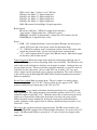
Joystick, 2 axis (2 An.)
7 buttons (Hike, Burst,
Throw, Switch, Arm
up, Arm down, and
joystick button) –
7 dig.
LEDs (8 dig)
PIC18F2321
microcontroller
RF circuit IC (3 SPI and
3 control, total 6 dig.)
PGM/SER port
(PGM 3 dig, SER 2 dig)
3 AAA
batteries
switch
3.3V
Reg
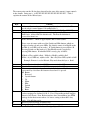
Figure 4: Block Diagram for AI-01 Remote Control
Remote Inputs:
Joystick, 2 axis so 2 analog inputs (also has digital button switch)
7 button switches so 7 digital lines
Outputs:
8 LEDs (6 yellow, 1 red, 1 green), 8 digital output lines
Bi-directional:
RF circuit, 6 digital lines, 3 SPI, 3 control
Power:
4 AAA batteries go into compartment on bottom. Battery voltage goes into 3.3V
linear regulator, with 500 mA max output (same as used on robot). 3.3V is the only
voltage used on the board (nRF24L01 has an internally generated 1.7V, see data sheet for
more detail).
Operation description: The remote is based on the Microchip PIC18F2321
microcontroller. The remote’s inputs are the joystick and buttons. Outputs are LEDs and
the RF circuit. User operates joystick and buttons. Software analyzes these inputs and
transmits a packet of data about every 60 ms that contains information about the state of
the inputs.
Joystick is a 2 axis 10Kohm analog potentiometer. Output voltage is about 1.65V when
in neutral position on X or Y axis. Min 100 mV to about 3.26V max.