1
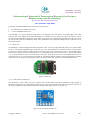
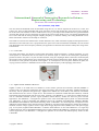
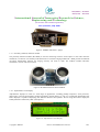
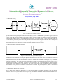
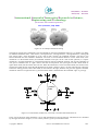
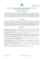
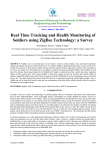
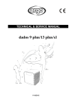
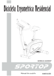
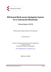
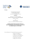
ISSN(Online) : 2319-8753 ISSN (Print) : 2347-6710 International Journal of Innovative Research in Science, Engineering and Technology (An ISO 3297: 2007 Certified Organization) Vol. 4, Issue 7, July 2015 A Review on Real Time Breath Processing Based Embedded Wheelchair for Quadriplegic People Umeshkumar Jaiswar¹, Sanjna S. Repal² P.G. Student, Department of Electronics and Telecommunication Engineering, MCT’s RGIT College, Andheri (W), Mumbai, Maharashtra, India1 Assistant Professor, Department of Electronics and Telecommunication Engineering, MCT’s RGIT College, Andheri (W), Mumbai, Maharashtra, India2 ABSTRACT: The project “A Review on Real Time Breath Processing Based Embedded Wheelchair for Quadriplegic People” is basically a wheelchair, which is controlled with the help of normal inhalation and exhalation of breath using MIC (microphone) and signal conditioning circuit. Depending upon the breath taken in and out, the wheelchair functions will activate and it will move Forward, Backward, and Left and Right directions with the help of accelerometer. The movement of the wheelchair is controlled by a MCU (Microcontroller Unit). The system is divided into two main units: Micro-electro mechanical systems (MEMs) Sensor unit and wheelchair control unit. The MEMs sensor (accelerometer), which is placed on head, provides head motion detection with analog output. So this can be used by persons with higher degree of impairment, such as quadriplegics, i.e. persons that cannot move any of the body parts, except of the head. Motion of the wheelchair is controlled wirelessly with the help of ZigBee transceiver. Medical devices designed to help them are very complicated, rare and expensive. In this paper a microcontroller system that enables standard electric wheelchair control by breathe and head motion is presented. KEYWORDS: Accelerometer, MIC, ARM7 microprocessor, ZigBee, Proximity sensor, DC motors. I. INTRODUCTION People with physical disabilities (Quadriplegics) and partial paralysis always find difficulty to navigate their normal work without the help of someone. Often after paralysis or physical disability, the wheelchair is the most common means of locomotion for such people. With the present developments in the field of robotics, embedded system and artificial intelligence a successful designs are been developed, to easily solve this matter at very low cost [1]. In this paper the wheelchair can controlled from several meters wirelessly without actually sitting on it. The chair can be controlled by head motion with directions as needed. Some existing wheelchairs are fitted with PC for the gesture recognition. But making use of the PC along with the chair makes it bulkier and increases complexity. This complexity is reduced by making use of the MEMs accelerometer. The size of accelerometer is very compact and can be placed on the cap that is placed on the head of the patients. Other existing systems, which make use of the similar kind of sensors are wired, which again increases the complexity of the system. They also limit the long range communication [2]. This complexity is removed by using the ZigBee technology. Signals can be transmit through ZigBee over large distances. Irrespective of line of sight communication, signals through ZigBee travel even when there is obstruction between the transmitter and receiver. In this paper, basically a wheelchair is used to control with the help of inhalation and exhalation of breathe using MIC. A microcontroller system that enables standard electric wireless wheelchair control by head motion is developed. Accelerometer (which is placed on head) is controlled by person’s breathe and Depending upon the breath, the wheelchair will move into desired directions with the help of accelerometer. Copyright to IJIRSET DOI:10.15680/IJIRSET.2015.0407101 5575 ISSN(Online) : 2319-8753 ISSN (Print) : 2347-6710 International Journal of Innovative Research in Science, Engineering and Technology (An ISO 3297: 2007 Certified Organization) Vol. 4, Issue 7, July 2015 The prototype consists of the control unit (an accelerometer and a microcontroller) and a mechanical actuator. The accelerometer is used to collect head motion data. To process the sensor data, a novel algorithm is implemented using a microcontroller. The output of the control unit is given through ZigBee module to the mechanical actuator, which is used to position the wheelchair with the user’s command. Thus, user head motion data is transmitted wirelessly to wheelchair unit and wheelchair motion is controlled by user. II. LITERATURE REVIEW Unfortunately, the number of disabled people is increasing by tragic accidents. Some victims of the accidents are suffering from abnormal life with serious spinal injuries. According to a recent study 5,596,000 people in the India live with paralysis. About one million, 16% of these people cannot carry out daily task without continuous help. 2.1 Head Motion Controlled Power Wheelchair According to this paper Electric powered wheelchair is controlled by head control device. It uses head movements detected by the motion data obtained from the gyroscope of an Emotive sensor [3]. It has two control modes, one mode uses only one head movement (‘up’ or ‘down’) and the other one employs four head movements (‘up’, ‘down’, ‘right’ and ‘left’). Figure 1: Head controller Four control commands were implemented, namely ‘going forward’, ‘turning right’, ‘turning left’ and ‘stopping’. In both control modes, the user does not have to maintain the head movement during the control command [3]. This device is good option for the users who have ability to move their head on their own but not good for the users with bad head movement ability. 2.2 Robot Wheelchair Using Eye Blink Sensors and Accelerometer The aim of this paper is that driving a wheelchair by using persons eye blinking. In this project Robotic wheelchair user’s eye blink and head tilt movement to steer the wheelchair [4]. But for the detection of eye movement we need IR sensors and IR sensors can cause malfunctions some times to eyes since eye blinking cannot be controlled for a long time. IR sensors are also said to damage the eye. Therefore this wheelchair is not comfortable to patient. 2.3 Accelerometer Based Hand Gesture Controlled Wheelchair The purpose of this study is to present a reliable means for human-computer interfacing based on hand gestures made in three dimensions. In this paper they discuss the development of a novel architecture of an intelligent wheelchair working on wireless hand gesture control and not by the usual method of keypad for the physically handicapped people. Unlike others, this project also has a distress call system (GSM) to alert the concerned people or family in times of necessity for the person, by the person from an alert switch or when there is any sudden detection of edge or staircase during backward motion, thus saving the chair from accidents [7]. In this system is divided into two parts: MEMs Sensor and wheelchair control. The MEMs sensor (which is connected to hand) is an 3-axis accelerometer that provides hand gesture detection, converts it into the 6- bit digital values and gives it to the PIC controller. Copyright to IJIRSET DOI:10.15680/IJIRSET.2015.0407101 5576 ISSN(Online) : 2319-8753 ISSN (Print) : 2347-6710 International Journal of Innovative Research in Science, Engineering and Technology (An ISO 3297: 2007 Certified Organization) Vol. 4, Issue 7, July 2015 To avoid physical hardship, the user can use their finger instead of hand and the user gets the ability and freedom to turn the wheelchair into the desired direction. Of course some training is required to use the accelerometer as it’s quite sensitive. But at the end this technology could not be a better use for an individual who has bad hand movement and strength [7]. 2.4 Designing and Modeling of Voice Controlled Wheelchair The methodology in this paper is that, when user speaks commands, a microphone detects the vibration of vocal cord. This microphone is interfaced with PC and using user voice commands wheelchair is controlled. But this system could be unstable for powered wheelchair control in noisy environments [9]. Figure 2: Voice activated powered wheelchair III. PROBLEM STATEMENT Electric wheelchairs are designed to help paraplegics people. Unfortunately, this cannot be used by persons with higher degree of impairment, such as quadriplegics, i.e. persons that, due to age or illness, cannot move any of the body parts, except of the head. Medical devices designed to help them are very complicated, rare and expensive [1]. 3.1 Drawbacks of existing wheelchair technologies: There are many shortcomings are present in existing technologies. Some of them are described below. 3.1.1 Sip-and-puff wheelchair This technology is a method of using air pressure to control wheelchair by sipping and puffing. Sharp sips and puffs can be used to change the speed and direction of the wheelchair. Steering is accomplished by lower-level and highlevel sips and puffs. But this is not good for individual with week breathing [2]. 3.1.2 Eye controlled wheelchair In Eye controlled wheelchair, for the detection of eye movement, we need IR sensors and IR sensors can cause malfunctions some times to eyes since eye blinking cannot be controlled for a long time. IR sensors are also said to damage the eye. Therefore this wheelchair is not comfortable to patients [4]. 3.1.3 Brain controlled wheelchair Brain controlled wheelchair is very costly. In this paper, Research and studies have revealed that there might be chance of brain tumours. In that case, the wheelchair is not safe for patients [10]. Copyright to IJIRSET DOI:10.15680/IJIRSET.2015.0407101 5577 ISSN(Online) : 2319-8753 ISSN (Print) : 2347-6710 International Journal of Innovative Research in Science, Engineering and Technology (An ISO 3297: 2007 Certified Organization) Vol. 4, Issue 7, July 2015 So, we come with the new idea of controlling a wheelchair with head motion and breath (inhaling and exhaling).In this project the proposed wheelchair can be controlled by inhaling and exhaling the breath of the person. User just needs to breathe in and out to activate the system and move wheelchair into the required direction with the help of accelerometer. And this wheelchair can be controlled automatically by wireless sensor network (WSN). IV. PROPOSED SYSTEM ARCHITECTURE The Architecture of our proposed system is composed of two parts: 4.1 Control Unit: The system consists of two main units: Control unit (Transmitter part) and Wheelchair unit (Receiver part). In control unit, an accelerometer (for controlling the movements), MIC (for detect the breathing of person), LCD display and buzzer (to indicate the hard conditions) are used. Breath data, received from the microphone will be given to the microcontroller which will activate the control unit. The head motion or gesture information is collected by the accelerometer, whose output is directly connected to the microcontroller and then the processed data of transmitter side will be transmitted to the receiver side through wireless transceiver (ZigBee). Fig. 4.1 shows the block diagram of the transmitter unit. The user commands are indicate on display. If users breathe rate is increases or decreases, in that situation the buzzer will generate sound. Figure 3: Control Unit (Transmitter) 4.2 Wheelchair Unit: The same data is received at receiver side by the Zigbee module. DC Motors, which are interfaced to the controller by the motor driver IC, control the directions of the wheelchair. Fig. 4.2 shows the block diagram of the wheelchair unit. A proximity (obstacle) sensor is used to protect the wheelchair from the obstacles. User’s breath rate will display on LCD. Copyright to IJIRSET DOI:10.15680/IJIRSET.2015.0407101 5578 ISSN(Online) : 2319-8753 ISSN (Print) : 2347-6710 International Journal of Innovative Research in Science, Engineering and Technology (An ISO 3297: 2007 Certified Organization) Vol. 4, Issue 7, July 2015 Figure 4: Wheelchair Unit (Receiver) V. DESIGN DESCRIPTION AND SYSTEM MODULES The design description and system modules of our proposed system consist of two main sections: 5.1 Hardware Description In this project, LPC2148 microcontroller based on 32-bit ARM7 TDMI-S is used to access the data from Microphone and accelerometer. ARM7 microprocessor is used to process all the data in real time. Accelerometer (3-axis) is used to recognized head motion to control the wheelchair and MIC is used to detect user’s breath. To convert the analog output of sensors into strong electrical signal, we will use a signal conditioning circuit (i.e. transducer). As the processing is carried out on digital data, so these analog data will be converted into digital data by using ADC which is inbuilt in ARM 7 microprocessor. Therefore the output of the signal conditioning circuit will directly connected to the microprocessor. 5.1.1 LPC2148 Microcontroller The LPC2148 microcontrollers are based on a 32/16 bit ARM7TDMI-S CPU with real-time emulation and embedded trace support, that combines the microcontroller with embedded high speed flash memory ranging from 32 kB to 512 kB. A 128-bit wide memory interface and unique accelerator architecture enable 32-bit code execution at the maximum clock rate. For critical code size applications, the alternative 16-bit Thumb mode reduces code by more than 30 % with minimal performance penalty. Due to their tiny size and low power consumption, LPC2148 are ideal for applications where miniaturization is a key requirement, such as access control and point-of-sale. A blend of serial communications interfaces ranging from a USB 2.0 Full Speed device, multiple UARTs, SPI, SSP to I2C-Bus, and on-chip SRAM of 8 kB up to 40 kB, make these devices very well suited for communication gateways and protocol converters, soft modems, voice recognition and low end imaging, providing both large buffer size and high processing power. Various 32-bit timers, single or dual 10-bit ADC(s), 10-bit DAC, PWM channels and 45 fast GPIO lines with up to nine edge or level sensitive external interrupt pins make these microcontrollers particularly suitable for industrial control and medical systems [11]. Copyright to IJIRSET DOI:10.15680/IJIRSET.2015.0407101 5579 ISSN(Online) : 2319-8753 ISSN (Print) : 2347-6710 International Journal of Innovative Research in Science, Engineering and Technology (An ISO 3297: 2007 Certified Organization) Vol. 4, Issue 7, July 2015 1. Fast General Purpose Parallel I/O (GPIO): The device pins that are not connected to a specific peripheral function are controlled by the GPIO registers. Pins may be dynamically configured as inputs or outputs. LPC2148 introduce accelerated GPIO functions over prior LPC2000 devices. Every physical GPIO port is accessible via either the group of registers providing an enhanced feature and accelerated port access or the legacy group of registers. The Accelerated GPIO functions: GPIO registers are relocated to the ARM local bus so that the fastest possible I/O timing can be achieved. Mask registers allow treating sets of port bits as a group, leaving other bits unchanged. All registers are byte and half-word addressable. Entire port value can be written in one instruction. Bit-level set and clear registers allow a single instruction set or clear of any number of bits in one port. Direction control of individual bits. All I/O default to inputs after reset. Backward compatibility with other earlier devices is maintained with legacy registers appearing at the original addresses at the APB bus. Separate control of output set and clear. 2. 10-Bit ADC: The LPC2148 contain two analog to digital converters. These converters are single 10-bit successive approximation analog to digital converters. While ADC0 has six channels, ADC1 has eight channels. Therefore, total number of available ADC inputs for LPC2148 is 14. Basic clocking for the A/D converters is provided by the APB clock. A programmable divider is included in each converter, to scale this clock to the 4.5 MHz (max) clock needed by the successive approximation process. A fully accurate conversion requires 11 of these clocks. Features of ADC: 10 bit successive approximation analog to digital converter (i.e. two in LPC2148). Input multiplexing among 6 or 8 pins (ADC0 and ADC1). Power-down mode. Measurement ranges 0V to VREF (typically 3V; not to exceed VDDA voltage level). 10 bit conversion time ≥ 2.44 µs. Burst conversion mode for single or multiple inputs. Optional conversion on transition on input pin or Timer Match signal. Global Start command for both converters. 5.1.2 ARM7 Microprocessor The LPC2148 is embedded with ARM7TDMI-S microprocessor. The TDMI-S stands for 16-bit Thumb + JTAG Debug + fast Multiplier + enhanced ICE + Synthesizable core. Where T: supports both ARM (32-bit) and Thumb (16-bit) instruction sets, D: Contains Joint Test Action Group (JTAG) Debug extensions, M: Enhanced 32x8 Multiplier block, I: Embedded In-Circuit Emulator (ICE) macro cell, S: Synthesizable (i.e. distributed as Register Transfer Level (RTL) rather than a hardened layout). The ARM7TDMI-S is a general purpose 32-bit microprocessor, which offers high performance and very low power consumption. The ARM7TDMI-S processor also employs a unique architectural strategy known as THUMB, which makes it ideally suited to high-volume applications with memory restrictions, or applications where code density is an issue. The key idea behind THUMB is that of a super-reduced instruction set [11]. Copyright to IJIRSET DOI:10.15680/IJIRSET.2015.0407101 5580 ISSN(Online) : 2319-8753 ISSN (Print) : 2347-6710 International Journal of Innovative Research in Science, Engineering and Technology (An ISO 3297: 2007 Certified Organization) Vol. 4, Issue 7, July 2015 Essentially, the ARM7TDMI-S processor has two instruction sets: The standard 32-bit ARM instruction set. A 16-bit THUMB instruction set. The THUMB set’s 16-bit instruction length allows it to approach twice the density of standard ARM code while retaining most of the ARM’s performance advantage over a traditional 16-bit processor using 16-bit registers. This is possible because THUMB code operates on the same 32-bit register set as ARM code. THUMB code is able to provide up to 65% of the code size of ARM, and 160% of the performance of an equivalent ARM processor connected to a 16bit memory system. 5.1.3 MAX 232 The MAX232 is a Maxim Integrated Product designed in 1987. It converts signal from RS-232 level to signal suitable for use in TTL/CMOS compatible logic circuits and vice-versa. The MAX232 IC is a dual driver/receiver that includes a capacitive voltage generator to supply TIA/EIA-232-F (RS-232) voltage levels from a single 5V TTL/CMOS supply. Each receiver converts TIA/EIA-232-F inputs to 5V TTL/CMOS levels. These receivers have a typical threshold of 1.3V, a typical hysteresis of 0.5V, and can accept ±30V inputs. Each driver converts 5V TTL/CMOS input levels into TIA/EIA-232-F levels. The TIA/EIA-232-F stands for Telecommunications Industry Association/Electronic Industry Association-232-F, which is more popularly referred to RS-232 where ‘RS’ stands for ‘Recommended Standard’. Figure 5: MAX 232 5.1.4 Accelerometer (ADXL335) The ADXL335 is a thin, small, low power, complete 3-axis accelerometer with signal conditioned voltage outputs. It measures acceleration with a minimum full-scale range 3g. This device measures the static acceleration of gravity in tilt-sensing applications and dynamic acceleration resulting from motion, shock, or vibration [7]. Figure 6: Accelerometer (ADXL335) Copyright to IJIRSET DOI:10.15680/IJIRSET.2015.0407101 5581 ISSN(Online) : 2319-8753 ISSN (Print) : 2347-6710 International Journal of Innovative Research in Science, Engineering and Technology (An ISO 3297: 2007 Certified Organization) Vol. 4, Issue 7, July 2015 The user selects the bandwidth of the accelerometer using the CX, CY, and CZ capacitors at the X-OUT, Y-OUT, and Z-OUT pins. There are few bandwidths that can be selected to suit the task needed. They range from 0.5 Hz to 1600 Hz for the X and Y axes and from 0.5 Hz to 550 Hz for the Z axis [7]. The output of the ADXL335 has a typical bandwidth of greater than 500 Hz. The user must filter the signal at this point to limit aliasing errors. The analog bandwidth must be no more than half the analog-to-digital sampling frequency to minimize aliasing. The analog bandwidth can be further decreased to reduce noise and improve resolution. The ADXL335 noise has the characteristics of white Gaussian noise, which contributes equally at all frequencies and is described in terms of Hz (the noise is proportional to the square root of the accelerometer bandwidth). The user should limit bandwidth to the lowest frequency needed by the application to maximize the resolution and dynamic range of the accelerometer. 5.1.5 Carbon MIC The carbon microphone, also known as carbon button microphone, button microphone, or carbon transmitter, is a type of microphone or a transducer that converts sound to an electrical signal. It consists of two metal plates separated by granules of carbon. One plate is very thin and faces outward, acting as a diaphragm. When sound waves strike this plate, the pressure on the granules change, and it changes the electrical resistance between the plates. Higher pressure lowers the resistance as the granules are pushed closer together. As a steady direct current is passes between the plates, the varying resistance results in a modulation of the current at the same frequency of the impinging sound waves. Figure 7: Carbon MIC 5.1.6 ZigBee Module NORDIC nRF24L01+ ZigBee is based on an IEEE 802.15.4 standard to create wireless personal area networks (WPANs).ZIGBEE is typically used in low data rate applications that require long battery life and secure networking (ZigBee networks are secured by 128 bit symmetric encryption keys). ZigBee has a defined rate of 250 Kbit/s, best suited for intermittent data transmissions from a sensor or input device. This module has worldwide 2.4GHz ISM (The industrial, scientific and medical radio bands) bands and ultra low power operation. The nRF24L01+ is a single chip 2.4GHz transceiver with an embedded baseband protocol engine (Enhanced Shock Bust™), suitable for ultra low power wireless applications. The nRF24L01+ is designed for operation in the world wide ISM frequency band at 2.400-2.4835GHz [12]. nRF24L01+ is drop in compatible with nRF24L01 and on air compatible with nRF2401A, nRF2402, nRF24E1 and nRF24E2.Intermodulation and wideband blocking values in nRF24L01+ are much improved in comparison to the nRF24L01 and the addition of the internal filtering to nRF24L01+ has improved the margins for meeting RF regulatory standards. Internal voltage regulators ensure a high Power Supply Rejection Ratio (PSRR) and a wide power supply [12]. In our system, ZigBee module nRF24L01+ of Nordic Semiconductors is used. The nRF24L01+ is a single chip 2.4GHz transceiver with an embedded baseband protocol engine (Enhanced ShockBust™), suitable for ultra low power wireless applications. The nRF24L01+ is designed for operation in the world wide ISM frequency band at 2.4002.4835GHz. Copyright to IJIRSET DOI:10.15680/IJIRSET.2015.0407101 5582 ISSN(Online) : 2319-8753 ISSN (Print) : 2347-6710 International Journal of Innovative Research in Science, Engineering and Technology (An ISO 3297: 2007 Certified Organization) Vol. 4, Issue 7, July 2015 Figure 8: NORDIC nRF24L01+ plugin 5.1.7 Proximity (obstacle) detection module The proximity detection module (HC-SR04) is used for measuring closeness of the objects or the walls when the wheelchair is in motion. It is basically an IR based sensor. Ultrasonic ranging module HC - SR04 provides 2cm-400cm on-contact measurement function, the ranging accuracy can reach to 3mm. The modules includes ultrasonic transmitters, receiver and control circuit. Figure 9: HC-SR04 Ultrasonic Sensor Module 5.1.8 Alphanumeric LCD Display Alphanumeric displays are used in a wide range of applications, including palmtop computers, word processors, photocopiers, point of sale terminals, medical instruments, cellular phones, etc. The 16 x 2 intelligent alphanumeric dot matrix displays is capable of displaying 224 different characters and symbols. We are using this LCD to display the health parameters measured by MIC (microphone). Figure 10: Alphanumeric LCD Display Copyright to IJIRSET DOI:10.15680/IJIRSET.2015.0407101 5583 ISSN(Online) : 2319-8753 ISSN (Print) : 2347-6710 International Journal of Innovative Research in Science, Engineering and Technology (An ISO 3297: 2007 Certified Organization) Vol. 4, Issue 7, July 2015 5.1.9 Buzzer The buzzer is used to generate sound signal when the breath pressure or breath rate of user decreases or increases, below or above the normal breath rate. So this technique is implemented for monitoring the user’s health. If wheelchair will be going to collapse to any obstacle, in that situation alarm or buzzer will also generate sound signal. Figure 11: Buzzer 5.2 Software Description Software is a basic building block for the every system which designs the processing and operations. Following are the software’s used in designing of the proposed system. For programming of ARM7 microprocessor, embedded c language using Keil µVision4 software is used. The new Keil µVision4 IDE has been designed to enhance developer's productivity, also enabling faster and more efficient program development. µVision4 introduces a flexible window management system, enables us to drag and drop individual windows anywhere on the visual surface including support for Multiple Monitors. The Graphical user interface (GUI) coding needs VB.Net language. Visual Basic is a legacy third generation eventdriven programming language and integrated development environment (IDE) Microsoft. Microsoft intended Visual Basic to be relatively easy to learn and use. Visual Basic was derived from BASIC (Beginner’s All-purpose Symbolic Instruction Code) and enables the rapid application development (RAD) of graphical user interface (GUI) applications, access to databases using Data Access Objects, Remote Data Objects, or ActiveX Data Objects, and creation of ActiveX controls and objects. To display the data received by ZigBee on servers PC, a PL-2303 driver for USB-to-Serial adapter has installed on that PC. This driver helps to access the data on PC, through USB adapter of ZigBee transceiver. To designing the schematic circuit diagram and PCB Layout, Cadsoft EAGLE software is used. This software is less complex, easy to learn and helps to design circuit diagram in professional manner. VI. METHODOLOGY In this project wheelchair is operated using head motion and to sense the head motion, MEMs accelerometer is being used. Micro Electro Mechanical Systems (MEMS) is the integration of mechanical elements, sensors, actuators, and electronics on a common silicon substrate through micro fabrication technology. An accelerometer is an electromechanical device that measures acceleration forces and tilting angle from the ground [6]. In this model we are using ADXL335 accelerometer, which is 3axis accelerometer and gives analog output. 10 bit ADC that is already present in LPC2148 microcontroller converts this analog output to digital output. Copyright to IJIRSET DOI:10.15680/IJIRSET.2015.0407101 5584 ISSN(Online) : 2319-8753 ISSN (Print) : 2347-6710 International Journal of Innovative Research in Science, Engineering and Technology (An ISO 3297: 2007 Certified Organization) Vol. 4, Issue 7, July 2015 6.1 Breath Processing Figure 12: Guidance by breath expulsion First wheelchair system will activate by breath pressure which is given to the MIC and the movement will be controlled by head motion. Learning to operate the wheelchair is very easy. Breath pressure (inhaling and exhaling) of user, which is given to the MIC also help to monitor the health condition of person. Breath rate of user in normal range indicates normal health condition of person. If breath rate of user decreases or increases, below or above the normal breath rate (i.e. 20-40 breath per minute), then buzzer will generate sound signal and that changed breath rate will be displayed on LCD. LCD is mounted behind the wheelchair, so anyone can see the changing of user’s breath rate. The main measurement and control component is a circuit board that is placed on the user’s head. 6.2 Microcontroller system block diagram Figure 13: Microcontroller system block diagram The direction of the wheelchair and its speed depend on how the user tilts their head. If the user tilts his/ her head at an angle (about 30°) to any desired direction (forward, backward, left and right), the wheelchair will turn in that direction. The greater the head tilt, the faster the wheelchair will travel. If head is tilt more than cut off angle (>30°), wheelchair will stop automatically. The prototype consists of the digital system (an accelerometer and a microcontroller) and a mechanical actuator. The accelerometer is used to collect head motion data. A novel algorithm is implemented for processing the sensors data using a microcontroller. The output of the digital system is connected with the wheelchair unit, which is used to position the wheelchair with the user’s command. The proximity sensor, which is connected to wheelchair unit, protects it from the wall and any other obstacles. 6.3 Head Motion Recognition Algorithm Since a set of possible motions in this case is very small and the number of available commands is also very limited. Thus, the control of the system allows the user to give only four different commands: forward, backward, left and right. This means that there are only four commands to be recognized by the accelerometer. Copyright to IJIRSET DOI:10.15680/IJIRSET.2015.0407101 5585 ISSN(Online) : 2319-8753 ISSN (Print) : 2347-6710 International Journal of Innovative Research in Science, Engineering and Technology (An ISO 3297: 2007 Certified Organization) Vol. 4, Issue 7, July 2015 Figure 14: An example of threshold setting The meaning of each of the commands is easy and depends on the present wheelchair state, Fig. 6.3 Namely; we define six different wheelchair states: “state of still”, “moving forward”, “moving forward”, “moving backward”, “turning left” and “turning right”. If the wheelchair is in the “state of still” position, the command “forward” will move it into forward direction and the command “backward” will move it into backward direction. On the other hand, if the wheelchair is in the forward motion, the command “backward” will put it in the “state of still” position (i.e. stop the wheelchair). And if the wheelchair is in the backward motion, then the command “forward” will stop the wheelchair. If user gives a command “left” or “right” while in the state of still position, the system goes into left rotation mode or right rotation mode, but the rotation does not start. When the wheelchair is in the left rotation mode, the rotation to the left will start when the user passes the left threshold circle which is shown in Fig 6.4. It stops when the user returns the head in the starting position. On the other hand, for the rotation to the right, when the user gives the opposite command, wheelchair will move in right direction e.g. the left rotation mode is finished when the command “right” is given [6]. Figure 15: Accelerometer (ADXL335) X-axis and Y-axis data with threshold circle In Fig. 6.4 all direction of the wheelchair is given with threshold circle and cut-off level. Threshold circle is bounded by two upper and lower voltages (i.e.1.2V to 2.0V), which is given by accelerometer data. Copyright to IJIRSET DOI:10.15680/IJIRSET.2015.0407101 5586 ISSN(Online) : 2319-8753 ISSN (Print) : 2347-6710 International Journal of Innovative Research in Science, Engineering and Technology (An ISO 3297: 2007 Certified Organization) Vol. 4, Issue 7, July 2015 Accelerometer gives analog output that is converted into voltage by microcontroller. These voltages are compared for the movement of wheelchair. If the input voltage is between the threshold circle voltage, then motion of the wheelchair will not start and if voltage is above the threshold level, then motion of wheelchair start and it will move in desired direction (i.e. Above 2.0V for “forward and right” direction and above 1.2V for “backward and left” direction). But when user tilt his/her head more than 30° (1.2V and 2.0V) and if it goes above the cut-off level, then movement of the wheelchair will stop automatically. That means motion of wheelchair is above the threshold level and below the cut-off level. VII. CONCLUSION In this paper a microcontroller system that enables standard electric wheelchair control by normal breath of user and head motion is presented. There are some drawbacks of existing wheelchair technologies, which are designed and implemented for quadriplegic people. So in this paper, wheelchair technology using normal breath and motion of head is better option for the quadriplegic people. The proposed wheelchair can be controlled automatically by wireless sensor network (WSN). But the wheelchair system will activate by inhaling and exhaling the breath of the person. He/she just need to breathe in and out to activate the system and move wheelchair into the required direction with the help of accelerometer. In this technology person’s health can be monitored with the help of user’s breath. REFERENCES [1] H.T. Nguyen, L.M. King, G. Knight, “Real Time Head Movement System and Embedded Linux Implementation for the Control of Power Wheelchairs”, Proceedings of the 26th Annual International Conference of the IEEE EMBS, San Francisco, CA, USA, September 1-5, 2004, 0-78038439-3/04/$20.00 © 2004 IEEE, pp: (4892-4895). [2] Motoji Yamamoto, Takeshi Ikeda, Yoshinobu Sasaki, “Real Time Analog Input Device Using Breath Pressure for the Operation of Powered Wheelchair”, 2008 IEEE International Conference on Robotics and Automation, Pasadena, CA, USA, May 19-23, 2008, 978-1-4244-16479/08/$25.00 © 2008 IEEE, pp: (3914-3919). [3] D.J. Kupetz, S.A. Wentzell, B.F. Busha, “Head Motion Controlled Power Wheelchair”, Bioengineering Conference, Proceedings of the 2010 IEEE 36th Annual Northeast, March 26-28, 2010, 978-1-4244-6924-6/10/$26.00 © 2010 IEEE, pp: (1- 2). [4] Jzau-Sheng Lin, Win Ching Yang, “Wireless Brain Computer Interface for Electric Wheelchairs with EEG and Eye Blinking Signals”, International Journal of Innovative Computing Information and Control, ISSN: 1349-4198, Volume 8, Number 9, September 2012, pp: (6011-6024). [5] Ericka Janet Rechy-Ramirez, Huosheng Hu and Klaus McDonald-Maier “Head Movements Based Control of an Intelligent Wheelchair in an Indoor Environment”, Proceeding of the 2012 IEEE International conference on Robotics and Biomimetics, Guangzhou, China, December 11-14, 2012, 978-1-4673-2126-6/12/$31.00 © 2012 IEEE, pp: (1464-1469). [6] Aleksandar Pajkanovic, Branko Dokic, “Wheelchair Controlled by Head Motion”, Serbian Journal of Electrical Engineering, ISSN: 2217-7183, Volume 10, No. 1, February 2013, DOI: 10.2298/SJEE1301135P, pp: (135-151). [7] Diksha Goyal and Dr. S.P.S. Saini, “Accelerometer Based Hand Gesture Controlled Wheelchair”, International Journal on Emerging Technologies, ISSN: 2249-3255, Volume 4, Issue 2, June 2013, pp: (15-20). [8] Ericka Janet Rechy-Ramirez and Huosheng Hu, “Bi-modal Human Machine Interface for Controlling an Intelligent Wheelchair”, 2013 Fourth International Conference on Emerging Security Technologies, September 9-11, 2013, 978-0-7695-5077-0/13 © 2013 IEEE, DOI 10.1109/EST.2013.19, pp: (66-70). [9] Anoop.K.J, Inbaezhilan, Sathish Raj, Ramaseenivasan, CholaPandian, “Designing and Modeling of Voice Controlled Wheelchair Incorporated with Home Automation”, International Journal of Advanced Research in Electrical, Electronics and Instrumentation Engineering, ISO 3297: 2007, ISSN: 2278–8875, Volume 3, Issue 2, April 2014, pp: (53-60). [10] D.A. Craig, H.T. Nguyen, “Adaptive EEG Thought Pattern Classifier for Advanced Wheelchair Control”, Proceedings of the 29th Annual International Conference of the IEEE EMBS Cite Internationale, Lyon, France, August 23-26, 2007, 1-4244-0788-5/07/$20.00 © 2007 IEEE, pp: (2544-2547). [11] NXP Semiconductors, UM10139, LPC 214X User Manual, Rev. 4, 23 April 2012, pp: (1- 354). [12] Nordic Semiconductors, nRF24L01+ Single Chip 2.4GHz Transceiver, Product Specification V1.0, September 2008, pp: (1-8). Copyright to IJIRSET DOI:10.15680/IJIRSET.2015.0407101 5587