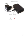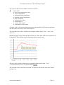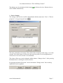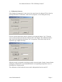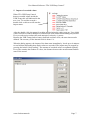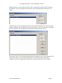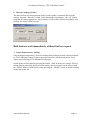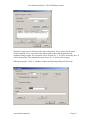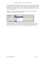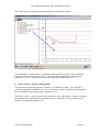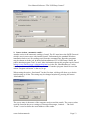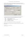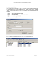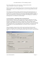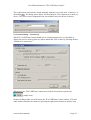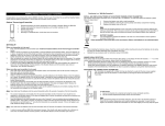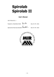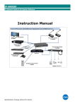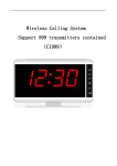
1
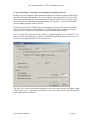
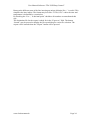
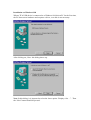
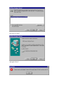
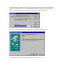
USB devices made by TFA Dostmann
31.1026 „USB-Temp“ PC Thermometer
31.1027 „USB-Batt“ Battery module for „USB-Temp“
User Manual
Version 2.9.2
05.08.2003
TFA Dostmann GmbH & Co. KG
Zum Ottersberg 12
97877 Wertheim / Reicholzheim
www.tfa-dostmann.de
TFA Devices User Manual
Contents
1.
Introduction................................................................................................................ 3
2.
USB-Temp .................................................................................................................. 4
3.
USB-Temp and USB-Battery .................................................................................... 5
www.tfa-dostmann.de
Page 2
TFA Devices User Manual
1. Introduction
The TFA device is a USB device, connected with a 2 m USB cable. The device will be
detected automatically by Windows® ME, Windows® 2000, Windows® XP und
Windows® .NET. Windows® 98 will ask some questions (see special chapter). (®
Microsoft Windows is a registered trademark of the Microsoft Corporation). The TFA
device would also operate with some versions of Linux.
No device driver are needed to operate the TFA device with Windows®. The already
installed standard USB drivers is sufficient. This protects the stability of the PC.
Depending of the configuration of the PC, more than 100 USB devices could be
connected. In case of Linux, only 16 TFA USB devices are supported.
Every TFA USB device has its own unique serial number. This makes it possible to
identify a certain device even the position in the USB hubs have changed. The serial
number could also be used by user programs so the device may be used as a simple
dongle.
The controlling of all TFA devices is done by the program „TFA USBTemp Control“.
This program will also do the visualization of the measured values and states. The
supplied software is described in the software manual.
Caution: It is strongly prohibited to use any of the TFA devices, if the failure of the
product may harm people. Usage in any medical applications is also prohibited.
www.tfa-dostmann.de
Page 3
TFA Devices User Manual
2. USB-Temp
The housing of the sensor is made of black anodized aluminium. It is filled with casting
resin which complies with the best non-inflammability class V-O as per UL 94. The size
of the sensor is 25 mm x 15 mm x 40 mm. The USB cable is about 2 m long. The current
needed by this USB device is less than 20 mA.
best place
to measure
To get the best results, the object to by measured should be placed at the position shown
above. The sensor is thermically connected with the aluminium housing so changes in
temperature will cause an immediate reaction.
The temperature is measured in steps of 0,0625° Celsius. The accuracy is at least +/-0.5°
Celsius. The sensor could be calibrated with the software “TFA USBTemp Control”.
Before delivery the USB-Temps are calibrated with an accuracy of 0,2° Celsius. The
operating temperature should be between -20° and +80° Celsius. Using it outside this
range may cause the destruction of the sensor. If temperature falls below 0° C the cable
must not be moved or bent.
The construction of the USB-Temp is very robust. Even hard conditions shown below do
not harm the sensor.
www.tfa-dostmann.de
Page 4
TFA Devices User Manual
The casting resign protects the sensor against humidity. The sensor must not be located
under water for a long time, because the plastic may suck up water very slowly. There is
no warranty that the materials of the sensor will not react with components of wet or
aggressive environments. Attention for use inside aquariums.
The display of the measured values are done with the software “TFA USBTemp Control”.
This software could be configured to activate an alarm on several ways.
3. USB-Temp and USB-Battery
By USB-Temp recording of temperature values without PC is possible. This is done by
plugging the USB connector to the power supply USB-Battery. The sensor runs than with
battery power and is capable to record 4000 values. The values are stored permanently,
even if the sensor will be disconnected. They must be deleted explicitly by a command
from „TFA USBTemp Control“. The time slice between the measurements are also
defined in „TFA USBTemp Control“.
As shown on the picture, an USB-Battery could supply up to two devices with power.
After connecting the sensor, the USB-Battery will be turned on. The measurement will
start when pressing the right push button (see below). The start of the measuring will be
acknowledged with a short light on the LED. Then every taken value is signaled by
flashing the LED. If the LED is turned on constantly, an error was detected. The reason
for that is in most cases a full measuring buffer.
On the left side of the USB-Battery a battery low indicator and an power plug could be
found. The USB-Battery is delivered with an AC/AD adapter running at 230V.
www.tfa-dostmann.de
Page 5
TFA Devices User Manual
Start button
Left
right
0
I
Battery power
switch
Battery low
AC/DC adapter
www.tfa-dostmann.de
Page 6
Software for the
USB device made by TFA Dostmann GmbH & Co.KG
User Manual
Software “TFA USBTemp Control”
Version 2.9.2
30.09.2003
TFA Dostmann GmbH & Co. KG
Zum Ottersberg 12
97877 Wertheim / Reicholzheim
www.tfa-dostmann.de
Germany
User Manual Software “TFA USBTemp Control”
Contents
1.
Introduction................................................................................................................ 2
2.
TFA USBTemp Control ............................................................................................ 3
3.
Device Settings............................................................................................................ 5
4.
Calibration (Sensors) ................................................................................................. 6
5.
Import of recorded values ......................................................................................... 7
6.
Recorder settings (Sensor) ........................................................................................ 9
7.
Switch Points (Sensor Actions) ................................................................................. 9
8.
Sensor Action „acoustic switch points“.................................................................. 12
9.
Sensor Action „automatic emails“.......................................................................... 13
10. Sensor Action „Start program “............................................................................. 15
11. Sensor Action „Event“............................................................................................. 16
12. System Settings – automatic file save ..................................................................... 18
13. System Settings – Optimizing memory needed and speed ................................... 19
14. System Settings – System tray ................................................................................ 20
15. System Settings –switching and measuring through the network....................... 21
16. Export of the measured values................................................................................ 23
1. Introduction
For operation of the TFA devices this Windows program is included in the distribution. It
allows a very simple and easy controlling of the devices.
www.tfa-dostmann.de
Page 2
User Manual Software “TFA USBTemp Control”
2. TFA USBTemp Control
Every TFA USB device will be configured and controlled by the application “TFA
USBTemp Control”. It will also do the visualization of values received from the devices.
The program window splits into two major windows. In the left tree based window the
connected devices and their properties are listed. The right data window displays
temperature curves.
www.tfa-dostmann.de
Page 3
User Manual Software “TFA USBTemp Control”
The entries in the left state window could be as follows:
sensor name
• device type temperature sensor
• current temperature
• minimal detected temperature
• maximal detected temperature
• State of recorder
• switch points (if any)
• refresh interval
• version of the sensor
• serial number of the sensor
A double click on the current temperature causes an immediate call for new temperature
data no matter of the state of the refresh interval.
The recorded values can be stored for later display with the menu „File“->“save“ and
„save as“.
When moving the cursor inside the data window the values next to the cursor position will
be displayed. This will help to get information about a specific time.
The time scale could be compressed or expanded with the menu point “View”>”increase/decrease view” or with the buttons
.
The recorded values could also be printed. The print out will use the same time scale as
the data view.
www.tfa-dostmann.de
Page 4
User Manual Software “TFA USBTemp Control”
The display may be refreshed with the button
will be added automatically.
to find new devices. Remote devices
3. Device Settings
The settings of the devices could be manipulated with the menu item “View”->”Device
properties” or by pressing the button
.
The device name has to be unique. The refresh interval must be in the range 1.5 to 3600
seconds. The refresh interval is the time between two probes. For most applications a
refresh rate of 10 to 60 seconds is recommended.
The colour of the curve can be changed with the button “Change colour”. After pressing
the button there is a dialog for colour selection.
By pressing the button “Recorder” next to the button “Change colour” the recording
capabilities can be regulated.
www.tfa-dostmann.de
Page 5
User Manual Software “TFA USBTemp Control”
4. Calibration (Sensors)
If the displayed temperature is not correct, the sensor has to be adjusted. This is done by
pressing the button “Calibration” in the device properties. A new dialog shows up:
First the current temperature must be fetched by pressing the button “Get”. Then the
correct value must be entered in the field next the “Set” button. The calibration will be
done when in the third step the button “Set” was pressed. These three steps may be
repeated to get a higher accuracy.
When the result is acceptable, the dialog could be closed with the „Ready“ button. Before
starting the calibration it is recommended that the corresponding temperature curve is
horizontal for a longer period.
The calibration is done inside the sensor and is independent from the used PC.
www.tfa-dostmann.de
Page 6
User Manual Software “TFA USBTemp Control”
5. Import of recorded values
When TFA USBTemp Control
detects recorded values inside the
USB-Temp, this will indicated in the
tree view. To read the records a
double click on this text will start the
import menu.
After the double click, the menu for reading and assigning the values pops up. Up to 4000
values could be recorded. Multiple record sessions even with different timing are possible.
Every record session reduces the total amount of values by 4 peaces.
Because the USB-Temps lacks a battery buffered real time clock, the start time must be
defined. The accuracy of the internal clock is about 1 %.
When the dialog appears, the import of the data starts immediately. It took up to 4 minutes
to read all data, depending how much values are recorded. The import may be stopped by
pressing the button “Stop reading”. The amount of recorded values are updated regularly.
Every line contains the number of values, the distance between the measurements and the
state of the record.
www.tfa-dostmann.de
Page 7
User Manual Software “TFA USBTemp Control”
When all data was received the start time of the record must be defined. This is done by
selecting the record, choosing the day and time on the right and then pressing the “set”
button.
After pressing “set” the computer checks the time and the duration of the record to avoid
conflicts with other records and already measured values. If all is ok, the time is displayed
in the left window. The assignment may be deleted with the button “delete”.
The button “finish” closes this dialog and inserts the assigned records in the program. The
values in the sensor are still valid. To delete the records in the sensor, the button
“Settings” open the configuration dialog of the sensor described in the next chapter.
www.tfa-dostmann.de
Page 8
User Manual Software “TFA USBTemp Control”
6. Recorder settings (Sensor)
The time between two measurements in the recorder mode is defined in the recorder
settings. Press the “Recorder” button. After entering the time distance , the “set” button
programs the sensor appropriate. Any available records will be deleted immediately after
pressing the button “delete records”.
Both buttons work immediately without further request.
7. Switch Points (Sensor Actions)
If the measured temperature is beyond a defined limit, different actions could be initiated
by TFA USBTemp Control. These temperature limits are called switch points. Every
sensor may define up to 256 different switch points.
Switch points will be added by pressing the button „Add“ in the device settings. When a
switch point is selected in the list of switch points, this switch point can be deleted with
the “Delete” button or modified by either pressing the “Modify” button or double clicking
on the item in the list.
www.tfa-dostmann.de
Page 9
User Manual Software “TFA USBTemp Control”
Different actions may be defined at the same temperature. Every action will be taken
which condition is true. Once taken the actions point will be deactivated until the
condition changes again. So if an email will be send at 40 ° C, it will be send only once. It
will be send again, if the temperature goes below 40 ° C and exceeds it again.
When pressing the „Add“ or „Modify“ button, the following dialog will show up:
www.tfa-dostmann.de
Page 10
User Manual Software “TFA USBTemp Control”
Here the temperature and change direction will be defined. In addition a second condition
may optionally defined that demands a continuously falling or rising temperature. The last
condition will be evaluated with four values. If all values are greater than the first one, the
curve is defined rising and if all values are less, falling. With this condition a very smooth
controller could be build.
Another condition that could case an alarm is the disappearance of the device. This
condition is the second entry in the dialog above.
Five different actions (sound, continuous sound, emails, program start and event) are
possible. The fields and buttons in the action field of the dialog will change dynamically
with the chosen action. The event action is available starting with Windows 2000.
www.tfa-dostmann.de
Page 11
User Manual Software “TFA USBTemp Control”
The switch points will be drawn with a dotted line in the data window.
All temperature switch points are evaluated with a hysteresis to get a secure switching
behaviour. The used hysteresis is 0.25 °Celsius. In the example above, the Switch is
turned on at 29.0 °C and turned off when the temperature falls below 28.75 °C.
8. Sensor Action „acoustic switch points“
The acoustic switch point types are “Sound” or “Continuous sound”. The “Sound” is
created by playing a sound file once. The “Continuous sound” is produced by playing the
file in an endless loop as long as the condition is true.
The field „Action“ is used to specify the sound file (.wav). The button “Search” will open
the standard file open dialog to search and specify a sound file. The sound file may be
played by pressing the button “Test”.
www.tfa-dostmann.de
Page 12
User Manual Software “TFA USBTemp Control”
9. Sensor Action „automatic emails“
Another action is the automatic sending of email. The PC must know the SMTP-Protocol
which is true in most cases with installed email. Unfortunately the standard Windows
installation lacks a tool for sending email from the command line. But other programs
may be chosen to do the job. In the default installation of TFA USBTemp Control, the
public domain program “blat” is used. More information about this program can be found
at http://www.interlog.com/~tcharron/blat.html or in the file „Blat Readme.txt” in the
installation directory of TFA USBTemp Control. If another program should be used the
action “Program execution” is the way to go.
When setting the action „Send email” for the first time, a dialog will show up to do the
initial setting as of blat. The setting may be changed anytime by pressing the button
“Mail address”.
The server name is the name of the computer used to send the emails. The correct values
could be found in the server settings of Netscape Messenger, Outlook … The field
“From” is used to define the email address of the sender.
www.tfa-dostmann.de
Page 13
User Manual Software “TFA USBTemp Control”
The field „Action“ is used to define the command line arguments used for the blat
program. The destination address is specified with „-t [email protected]“. The mail
subject is defined with the option “-s”
At the time the action was be taken the email arguments are filtered and some text
substitutions will take place. The following substitution pattern are possible:
%SN%
%T%
%DT%
%DA%
%TI%
Name of the temperature sensor
actual temperature
actual date and time, e.g. 02.05.2002, 11:54:23
actual date, e.g. 02.05.2002
actual time, e.g. 11:54:23
The button “Test” could be used to test if the email will reach the address .
The text of the email contains sensor name, temperature and time of the event. If may
look like this:
Temperature sensor: Server
Temperature = 22.0625 °Celsius
Time: 14:55:51
www.tfa-dostmann.de
Page 14
User Manual Software “TFA USBTemp Control”
10. Sensor Action „Start program “
With this action any available program on the PC could be started. This may be a special
email program, the shutdown of the PC or the entry in a log file. The command line is
defined in the action field and goes through the same substitution mechanism as the email
action. The following substitutions may be used:
%SN%
%T%
%DT%
%DA%
%TI%
Name of the temperature sensor
actual temperature
actual date and time, e.g. 02.05.2002, 11:54:23
actual date, e.g. 02.05.2002
actual time, e.g. 11:54:23
In this example the DOS command “echo” will be called to write some text at the end of a
file. The DOS shell will be reached with the “CMD” command. With Windows 98, the
“CMD” text must be replaced with “COMMAND.COM”. The contents of the file
“values.log” after executing the action above is as follows:
Server: 25.0000 at 15.11.2002 15:15:30
To find valid programs for execution, the button “Search” will open a file search dialog.
Reasonable examples could be to shut down the PC or to send an SMS by DOS
command.
www.tfa-dostmann.de
Page 15
User Manual Software “TFA USBTemp Control”
11. Sensor Action „Event“
With Windows 2000 or following an entry in the system event log could be written when
an action condition is true. TO do this the action type “Event” must be chosen. The field
“Action” is used to define the text to enter in the event log. Some replacement pattern are
available:
%SN%
%T%
%DT%
%DA%
%TI%
Name of the temperature sensor
actual temperature
actual date and time, e.g. 02.05.2002, 11:54:23
actual date, e.g. 02.05.2002
actual time, e.g. 11:54:23
In the Event Viewer the taken actions will show up in the Application Log.
www.tfa-dostmann.de
Page 16
User Manual Software “TFA USBTemp Control”
The event text looks like this:
www.tfa-dostmann.de
Page 17
User Manual Software “TFA USBTemp Control”
12. System Settings – automatic file save
Major TFA USBTemp Control settings are managed with the “System settings” dialog
located in the “View” menu. The settings for automatic file saving, compression, tray
display and networking are controlled here.
When a program or computer crashes all values stored in RAM will be lost. For that
reason, the data should be stored to disk from time to time using the file save menu item.
This saving could also be automated with the systems settings dialog item “automatic
saving”. The interval between savings must be specified as well as the path of the data
file. The “Search” button may be used to pick a file with the file search dialog.
The filename may contain substitution strings. They will be replaced at time the program
will be started. The following replacement strings are detected:
%SN%
%###%
%DT%
%DA%
%TI%
name of the sensor
automatic incremented number
start date and time of the program, e.g. 02.05.2002, 11:54:23
date of the program start, e.g. 02.05.2002
time of the program start, e.g. 11:54:23
www.tfa-dostmann.de
Page 18
User Manual Software “TFA USBTemp Control”
The setting in dialog shown on the last page, a filename that looks like
“Data_26.05.2003 11.44.36.cwc” will be used.
When leaving the system settings dialog with the “Ok” button this setting will be stored
and activated. To make sure the supplied path is ok, the first saving operation will start
immediately.
The settings are stored in the registry and used at the next time the program starts. To
avoid a inadvertent overwriting of the file, the system dialog will be opened when the
automatic save is selected. In some cases, the popup of the dialog should be avoided, e.g.
if the system should reboot automatically. The popup of the dialog may be disabled by
checking the box “Use filename, no acknowledge”.
13. System Settings – Optimizing memory needed and speed
When temperature sensors are used several weeks with a low refresh interval, a large
amount of memory will be needed to hold the values. When refreshing every 2 seconds
the memory consumption will be about 337 KB per day. This may lead to memory
problems and the display speed in the data window will slow down. This is the reason for
compressing the data. The used algorithm assures that minimum or maximum values will
be unmodified. It is also guaranteed that there is at least one value in a period of 10
minutes.
When selecting the compressed view check box the maximal used values must be
specified. The default value is 500000 values. When the specified amount of values is
reached, the compression will start automatically and reduces the count of values by about
50%.
www.tfa-dostmann.de
Page 19
User Manual Software “TFA USBTemp Control”
The compression could also be started manually with the view menu item “Compress” or
the button
. The dialog shown below will be displayed. The compression is done per
device. The value count is displayed in the text window below the device selection.
14. System Settings – System tray
When TFA USBTemp Control should run as a background process it is desirable to
display the process in the system tray when minimized. This is done by checking the box
„Minimize to system tray”.
When active the TFA USBTemp Control icon could be found in the system tray.
(sample icon)
Double clicking on the icon will restore the TFA USBTemp Control window. This and
other actions could also be chosen by pressing the right mouse button on the blue icon.
www.tfa-dostmann.de
Page 20
User Manual Software “TFA USBTemp Control”
15. System Settings –switching and measuring through the network
In many cases the sensored values should be displayed on another computer than the one
that owns the used USB interface. A typical example is the supervision of a server from
the system administrator PC or the controlling of rooms from the factory security. Even
the activation of an USB-Switch through the network is useful, e.g. to turn on the light
before looking through a remote camera.
For that reasons the TFA USBTemp Control software contains some network functions.
These functions are based on the sockets of TCP/IP which could be typically found on
nearly every PC. If there are problems the system administrator will help.
The PC to show the values and do the control is called the display server. On this PC, the
option “This is the display server” must be checked along with the port number to use. In
most cases the default number 54741 should be ok.
The other PCs (clients) who should send data to the server, must activate the option “Send
values to the server “. The name or IP number of the server must also be specified and the
port number must be identical.
www.tfa-dostmann.de
Page 21
User Manual Software “TFA USBTemp Control”
or
When TFA USBTemp Control is running on the client PC, the values are displayed
unchanged. The only difference is that the values are also transferred to the server. When
such remote data is received by the server, they will be displayed on the server with the
remote indicator “R” .
www.tfa-dostmann.de
Page 22
User Manual Software “TFA USBTemp Control”
16. Export of the measured values
To process the measured values with other programs these values could we exported to a
text file. The data export is configured with the “Export” dialog located in the “File”
menu.
The device whose data should be exported is selected in the list on the top of dialog. The
data could be cutted by defining a start and end time. The small grey text window below
the end time checkbox informs about the number of items that are found in the selected
time. This amount could be reduced by pressing the compress button on the left.
The only supported output form until now are text lines. The format of the lines must be
defined in the line format window. Several substitutions will be processed when the data
is exported:
%SN%
%T%
%DT%
%DA%
%TI%
Name of the temperature sensor
actual temperature
actual date and time, e.g. 02.05.2002, 11:54:23
actual date, e.g. 02.05.2002
actual time, e.g. 11:54:23
www.tfa-dostmann.de
Page 23
User Manual Software “TFA USBTemp Control”
Between the different parts of the line inserting an unique delimiter like ‘;’ is useful. This
simplifies the later import. The format may look like “%TI%;%T%” where the time and
temperature is delimited by a semicolon.
By checking the “Use ‘,’ as decimal point” checkbox all numbers are transformed this
way.
The destination file for the export is asked for in the “Export to” field. The button
“Search” may be pressed to display the file open dialog for easier file selection. The
export will be started when the “Export” button will be pressed.
www.tfa-dostmann.de
Page 24
Installation on Windows® 98
When a TFA USB device is connected to a Windows 98® driven PC for the first time,
the PC detects new hardware and requests a driver, even this is not necessary.
After clicking on „Next“ this dialog shows up:
Note: In this dialog, it is imported to select the lower option “Display a list …”. Then
the “Next” button should be pressed.
Just click on “Next”
und again “Next”:
After inserting the Windows 98 CD the already installed USB driver will be installed
again. So in almost every case, the reinstallation could be avoided by clicking on the
button “OK” without inserting the CD. Then the following dialog appears:
Just click on the button “Skip File” three times and the last dialog appears.
A last click on “Finish” button and the device is ready for use.