1
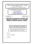
Operating Instructions / User manual
IRSoft
Version 2.0
Documentation software for ERSA Rework Systems
ERSA GmbH
Wertheim / Main
July 2002
ERSA has taken great care in the preparation of this Users Guide, however it cannot make any guarantees as to the content,
completeness and quality of the information it contains. The contents are updated regularly to reflect the latest changes. Due to the
fact that there is so much different hardware available on the market, we cannot guarantee that the combination of ERSA IRSoft
software and IR 550 A unit will work without problems, even when the computer specifications specified by us are adhered to.
To the extent permitted by law, no liability is assumed for any direct damage, consequential loss or damage to third parties resulting
from the purchase of this product.
All rights reserved. This manual may not be reproduced, transmitted or translated into another language, even in excerpt form,
without the written approval of ERSA GmbH.
Trademark
IBM PC is a registered trademark of International Business Machines Corporation. Microsoft is a registered trademark and Windows
is a trademark of Microsoft Corporation. All other products or company names mentioned in this manual serve purely for the
purposes of identification or description and may be trademarks or registered trademarks of their respective owners.
Date: July 2002
Copyright © 2002, by ERSA GmbH
ERSA IRSoft 2.0
Operating instructions / user manual
Contents
1.
Welcome to IRSoft
1.1.
1.2.
2.
3.
4.3.
4.4.
4.5.
4.6.
IRSoft User manual
5
The IRSoft user interfaces..........................................................................5
Adaption .....................................................................................................5
Usage of docking windows.........................................................................5
The elements of IRSoft
4.1.
4.2.
3
System requirements .................................................................................3
Installation of IRSoft ...................................................................................3
Connection PC and IR 550 A .....................................................................3
Starting IRSoft ............................................................................................4
Using the integrated help topics .................................................................4
The user interface
3.1.
3.2.
3.3.
4.
Introduction.................................................................................................1
The Elements of IRSoft ..............................................................................1
1.2.1. State window..................................................................................1
1.2.2. IRSoft view.....................................................................................1
1.2.3. Operator defined input ...................................................................1
1.2.4. Process values...............................................................................2
1.2.5. Parameter sets...............................................................................2
Installation of IRSoft
2.1.
2.2.
2.3.
2.4.
2.5.
1
7
The main view of IRSoft .............................................................................7
The toolbars of IRSoft ................................................................................8
4.2.1. The main toolbar ............................................................................8
4.2.2. The zoom toolbar ...........................................................................9
4.2.3. The view toolbar.............................................................................9
4.2.4. The record toolbar .......................................................................10
4.2.5. The analysis toolbar.....................................................................10
The pop up menu of the empty main window ..........................................11
The view of IRSoft ....................................................................................12
4.4.1. Depictable channels ....................................................................12
4.4.2. Settings of main view...................................................................13
4.4.3. The pop up menu of IRSoft view .................................................17
4.4.4. The hotkeys of the main view ......................................................17
The state window of IRSoft ......................................................................18
The operator defined input window of IRSoft ...........................................18
4.6.1. The parameter view .....................................................................19
4.6.2. The parameter Tinit .....................................................................19
4.6.3. The value table ............................................................................20
4.6.4. The profile table ...........................................................................20
4.6.5. Working with the profile table.......................................................21
4.6.6. The pop up menu of the profile table ...........................................21
4.6.7. Download of parameter sets........................................................21
4.6.8. The Download Assistant ..............................................................22
4.6.9. Upload of profile parameters .......................................................22
ERSA IRSoft 2.0
Operating instructions / user manual
4.6.10. The Upload Assistant .................................................................23
4.6.11. Parameter list protection ............................................................24
4.6.12. Storage of profile parameters ....................................................25
5.
Working with IRSoft
5.1.
5.2.
5.3.
5.4.
5.5.
5.6.
6.
7.
9.
10.
11.
IRSoft User manual
Index
36
Ways of contact........................................................................................36
Glossary
10.1.
36
How to uninstall ........................................................................................36
Contact to ERSA
9.1.
32
Adaption and creating of toolbars ............................................................32
Setting of options......................................................................................34
7.2.1. Interface settings .........................................................................34
7.2.2. Language setting .........................................................................35
7.2.3. General Settings ..........................................................................35
Deinstallation of IRSoft
8.1.
29
Description of the analysis funktions........................................................29
Activating Analysis Cursor........................................................................29
Moving the analysis cursor.......................................................................30
Setting analysis dots ................................................................................30
Adaption of IRSoft
7.1.
7.2.
8.
Set up communication..............................................................................26
Control via state window ..........................................................................27
Recording .................................................................................................27
5.3.1. Automatic recording .....................................................................27
Save recording .........................................................................................27
Print profiles .............................................................................................28
Download and upload of profile parameters ............................................28
Analysis functions
6.1.
6.2.
6.3.
6.4.
26
37
Unknown words ........................................................................................37
39
Welcome to IRSoft
ERSA IRSoft 2.0
Operating instructions / user manual
1. Welcome to IRSoft
1.1. Introduction
IRSoft is the ultimate tool for documentation of repeatable soldering processes in SMT
Rework.
IRSoft has been developed especially for this purpose and can be used together with an
ERSA IR 550 A Microprocessor controlled Rework System. By using IRSoft the operator
has the ability to visualize soldering profiles, edit soldering parameters and store those
information in order to fulfil the documentation requirements of modern industrial
organisations. The operator will be able to handle soldering parameters within IRSoft
very easily and download them to the IR 550 A unit.
By this any settings on the unit itself are not necessary. Some functions of the IR 550 A
can be remote controlled by IRSoft.
1.2. The Elements of IRSoft
1.2.1.
State window
IRSoft contains a separate window to display the actual state and values of the
connected IR 550 A unit. Within this window actual temperatures, switches and actions
as well as error messages and states of operation are clearly arranged (The state
window of IRSoft).
1.2.2.
IRSoft view
Within this view the profiles of the activated temperature channels are displayed, the
state of all active elements can be recorded. Additionally Reference lines can be
visualized. The temperature range and the displayed recording time can be set freely. A
scale and grid can be defined to achieve high-grade temperature plots. (The view of
IRSoft).
1.2.3.
Operator defined input
The Operator defined input window displays the actual programmed temperature profile.
It is possible to edit terms for the operated printed circuit board and the used component
as well as the shutter settings, the type of process and the orientation of the component
in the PCB holder. Additionally the name of the operator can be inserted and all
information can be saved for future use. (The operator defined input window of IRSoft).
IRSoft User manual
Welcome to IRSoft • 1
ERSA IRSoft 2.0
Operating instructions / user manual
1.2.4.
Process values
All transferred and stored temperature and process values are displayed in this table
and will be stored together with the actual plot in one file. (The value table).
1.2.5.
Parameter sets
This table contains all parameters for temperature profiles, shutter settings and as well
as the corresponding board and component names. This data can be transmitted to the
IR 550 A. It is also possible to upload parameters from the IR 550 A and add the board
and component name, before saving the parameters for later use. Thus a high
repeatability of the soldering process is guaranteed. (The parameter sets). This table
can be protected by a password.
IRSoft User manual
Welcome to IRSoft • 2
ERSA IRSoft 2.0
Operating instructions / user manual
2. Installation of IRSoft
2.1. System requirements
IRSoft is running on IBM compatible computer systems meeting the minimal system
requirements listed below. For optimal operation you should adapt your computer
system to those requirements and upgrade the system if you are working with large
files.
Minimal system requirements:
Processor:
Operating systems:
RAM:
Available hard disk space:
Pentium Class (300MHz)
Windows XP, ME, NT4.0, WIN2000
64 MB
30 MB
Optimum Operation:
Processor:
RAM:
Pentium > 500 MHz
>= 128 MB
The screen resolution is recommended to be not below 1024 * 768 pixel.
Note: IRSoft is running also on systems with the older operating systems
windows 95 and 98. The performance on those computers might be limited.
2.2. Installation of IRSoft
Close all applications before you start the installation of IRSoft on your computer
system. Insert the installation CD to the CD-ROM drive and start "IRSoftSetup.exe".
Now the set up program will be executed. Please follow the instructions.
2.3. Connection PC and IR 550 A
Connect the IR 550 A unit to a free RS232 COM port (serial port) on your. Please use
the included null modem cable. Now the communication between IR 550 A and IRSoft is
possible. Maybe you have to select the proper COM port within the software package.
Doing this please refer to section Set up communication.
IRSoft User manual
Installation of IRSoft • 3
ERSA IRSoft 2.0
Operating instructions / user manual
2.4. Starting IRSoft
After installation of IRSoft you can choose several ways to start the software. The
easiest way is to use the IRSoft icon, which will be set up to your desktop during
installation. When you double click on the IRSoft icon, the software will be started.
2.5. Using the integrated help topics
To receive online help the user has various possibilities.
Press the F1 key
Press the help button
Open the online help via the menu help
Context sensitive help:
In some windows you can receive help for a certain item by pressing the
button. Click
this button and move the mouse over the item you are looking for additional information.
Click once again and the corresponding help topic will be displayed.
The main toolbar
IRSoft User manual
Installation of IRSoft • 4
ERSA IRSoft 2.0
Operating instructions / user manual
3. The user interface
3.1. The IRSoft user interfaces
IRSoft is based on a main view to display temperature profiles. In addition to this main
view the operator can open further windows to get more information about the state of
the connected IR 550 A unit and has the ability to edit and change parameters of
temperature profiles. Detailed information to these windows you receive here.
The toolbars of IRSoft
The view of IRSoft
The state window of IRSoft
The operator defined input window of IRSoft
3.2. Adaption
IRSoft allows an individual adaption of the toolbars and the arrangement of the docking
windows. So IRSoft can be adjusted to the users individual preferences and habits.
More information you will find in the following sections.
Adaption and creating of toolbars
Setting of options
3.3. Usage of docking windows
Docking windows are windows belonging to a special application. Docking windows
have no fixed position within the main window. The user can arrange them freely within
the application. He is able to vary sizes and positions of a docking window. IRSoft
contains two docking windows, the state window and the operator defined input window.
Positioning of docking windows
A single docking window can be arranged within the application by clicking on the
double line and moving it around via drag and drop.
A double click on this bar changes the docking window into a so-called flying window.
This window is movable exceeding the boarders of the main window.
If a flying window gets in contact with the applications frames during movement it
switches back to a docking window. More features about docking and flying window you
IRSoft User manual
The user interface • 5
ERSA IRSoft 2.0
Operating instructions / user manual
receive in the pop up menu of the docking window. The pop up menu opens by pressing
the right mouse button over the window.
Change size
To change the size of a docking window you have to move the mouse over the frame of
a docking window until the cursor changes its shape to
. Now the size of the window can be modified by drag and drop.
All changes to a docking window are saved and remain during a restart of the software.
IRSoft User manual
The user interface • 6
ERSA IRSoft 2.0
Operating instructions / user manual
4. The elements of IRSoft
4.1. The main view of IRSoft
After the first start of IRSoft the user faces the following view on the screen.
On the top the menu bar is located. Below you will find the toolbars. On the right side
the state window is docked. At the bottom of the screen you will find the windows
“process values”, “operator defined input” and “parameter sets”. They are displayed as
three functional indices. A more detailed description will be given in the following
sections.
The view of IRSoft
The toolbars of IR Soft
The state window of IR Soft
The operator defined input window of IRSoft
IRSoft User manual
The elements of IRSoft • 7
ERSA IRSoft 2.0
Operating instructions / user manual
4.2. The toolbars of IRSoft
All functions of IRSoft can be activated very easy by the use of toolbars, containing the
correlated buttons. In the basic set up IRSoft contains four separate toolbars divided by
their function.
The main toolbar
The zoom toolbar
The view toolbar
The record toolbar
The analysis toolbar
4.2.1.
The main toolbar
The main toolbar contains the basic functions. It is displayed in the following way.
The function of the symbols are explained below:
These are standard functions for a new worksheet, to open an already
saved profile or to save the actual view.
This button converts the actual values of a soldering process to an Excel format
and exports the data.
This button activates the communication to the connected IR 550 A system.
This button is used to switch the bottom radiator of the IR 550 A system on and
off.
This button downloads the selected set of parameters in the parameter sets table
to the IR 550 A unit and activates the parameter set immediately. (Download of
parameter sets).
This button uploads the actual set of parameters from the IR 550 A and writes it
into the parameter sets table (Upload of profile parameters). At the same time settings
from the operator defined input window will be transferred.
This button activates the dialogue with IRSoft Options. The configuration of the
interface and the selected language can be set as well as further general options.
IRSoft User manual
The elements of IRSoft • 8
ERSA IRSoft 2.0
Operating instructions / user manual
These buttons are used to activate the dialogue with information about
IRSoft and the context sensitive online help.
4.2.2.
The zoom toolbar
The zoom toolbar contains all zoom functions of IRSoft.
This button changes the image in the working area to original size.
This button changes the zoom step by step. The user can change the zoom
factor manually by clicking the left mouse button for zooming in and the right button for
zooming out.
This button activates the zoom to selected window function. The user has to
press the left mouse button and create a frame. The zoom will be fit to the selected
window.
This button optimises the view to the size of the working area.
4.2.3.
The view toolbar
The view toolbar allows fading in and out of the docking windows. Additional a full
screen preview and a minimized view are possible.
This button activates the full screen preview for the actual working area. Pressing
the ESC key the program returns to normal view.
This button shows or hides the operator defined input window. The same result
will be achieved by pressing the F2 key.
This button shows or hides the state window. The same result will be achieved by
pressing the F3 key.
This button hides all docking windows (state window and operator defined input
window) at once. It is equivalent to the F5 key.
IRSoft User manual
The elements of IRSoft • 9
ERSA IRSoft 2.0
Operating instructions / user manual
This button hides all docking windows (state window and operator defined input
window) and at the same time minimizes the window of the application and positioned in
the upper left corner of the screen. It is equivalent to the F6 key.
4.2.4.
The record toolbar
This toolbar contains functions for recording temperature profiles and their parameters.
This button starts the recording of a temperature profile.
This button deletes the actual recording. All values and temperature plots get
lost.
This button opens the layout settings dialogue. Here changes regarding the
visualization of temperature profiles can be made.
Settings of main view
4.2.5.
The analysis toolbar
This toolbar contains functions for further analysis of the recorded temperature profile.
This button activates the analysis cursor and shows it on the screen. (See
Activating Analysis Cursor and Moving the analysis cursor).
The other buttons of this toolbar are used to set a new analysis dot or to erase either the
last or all analysis dots. (See Setting analysis dots)
IRSoft User manual
The elements of IRSoft • 10
ERSA IRSoft 2.0
Operating instructions / user manual
4.3. The pop up menu of the empty main window
If no view is opened, the user faces an empty working area. To open a new view the
button New has to be pressed.
Alternatively the user can open the pop up menu by clicking into the free space with the
right mouse button.
Here the most important functions of IRSoft are summarized and sorted by their
function.
The toolbars of IRSoft
IRSoft User manual
The elements of IRSoft • 11
ERSA IRSoft 2.0
Operating instructions / user manual
4.4. The view of IRSoft
The basic view of IRSoft shows temperature profiles and process parameters, recorded
from a connected IR 550 A Rework system.
The user can select scale, channels and colours. How to do this will be explained in the
next sections.
4.4.1.
Depict able channels
In this section information about selecting and depicting temperature channels will be
given.
The IR 550 A includes two different temperature sensors. With both of them temperature
profiles can be recorded. One is the integrated infrared sensor the other one is an
optional available thermocouple.
The display of the IR 550 A always shows the reading of the activated sensor. At the
same time this temperature reading is used to control the soldering process. Both
sensors are detecting the surface temperature of the component or the PCB. To transfer
this information to the temperature at the solder joint, the calibration function has been
implemented to the IR 550 A. When the user detects the melting of the used solder he
can calibrate the sensor reading to a specific liquid temperature.
The IR 550 A always displays the calibrated reading of the selected sensor. Using
IRSoft more possibilities open up.
All temperature sensors are recorded permanently. The operator can choose which
channels should be displayed or printed.
Settings of main view
IRSoft User manual
The elements of IRSoft • 12
ERSA IRSoft 2.0
Operating instructions / user manual
4.4.2.
Settings of main view
4.4.2.1.
Layout settings
Pressing the Layout settings button opens the selection window for settings of the
main view.
On the Layout index you will find settings for visualisation the temperature profile. The
user can set the temperature range and the time range to be displayed. Additionally
settings for the grid can be made.
4.4.2.2.
Channel selection
On the Channels index you can select the displayed temperature channels.
Additionally for the selected channels colours and line sizes can be set.
IRSoft User manual
The elements of IRSoft • 13
ERSA IRSoft 2.0
Operating instructions / user manual
4.4.2.3.
Setting the sampling rate
On this index page the sampling rate for the temperature recording can be set.
The sampling rate can be set in a range from 1 - 5 s. It defines the equidistant time
slices when a new value for recording is requested from the IR 550 A. The default
setting is 1 second and should not e modified without need.
4.4.2.4.
Process parameter settings
On this index the settings for the process parameter display can be modified.
The user can select, which parameter will be displayed and can set the colour of each
bar graph line.
IRSoft User manual
The elements of IRSoft • 14
ERSA IRSoft 2.0
Operating instructions / user manual
4.4.2.5.
Reference lines settings
On the last index page three reference lines can be selected. They can be displayed in
the main window and represent the parameters T1, T2 and T3.
To achieve a better contrast, also colours and line sizes can be selected.
IRSoft User manual
The elements of IRSoft • 15
ERSA IRSoft 2.0
Operating instructions / user manual
4.4.2.6.
IR 550 A options
Starting with firmware version 1.63 (IR 550 A), the IR 550 A unit is prepared for further
functions. The behaviour of the integrated buzzer can be modified via IRSoft. It is
possible to deactivate the automatic calibration procedure during desoldering.
Or you can set the automatic calibration to permanent trigger via IRSoft during
desoldering. In this mode the sensor signal will be calibrated automatically as soon as
the liquidus temperature is reached. The calibration will proceed until the vacuum
pipette lifts the component from the PCB.
4.4.2.7.
Record start options
The start options for recording of process parameters can be modified in this index. The
recording has not to be started manually by the operator. The software delivers the
following choices:
By swing in of the top radiator; starts recording when the top radiator reaches its
working position.
When Tinit is reached: Starts recording when the sensor detects the temperature Tinit
during rising temperatures.
No auto start function activation; Manual recording start.
IRSoft User manual
The elements of IRSoft • 16
ERSA IRSoft 2.0
Operating instructions / user manual
4.4.3.
The pop up menu of IRSoft view
In the IRSoft view, when a profile is displayed pressing the right mouse button can
activate a pop up menu.
Here the most important functions of IRSoft are summarized and sorted by their
function.
The toolbars of IRSoft
4.4.4.
The hotkeys of the main view
Functions that are used very often can be activated by keys of the keyboard. IRSoft
contains the following hotkeys:
F2
F3
F5
F6
F8
F9
F10
show / hide operator defined input window
show / hide state window
hide operator defined input window and state
window
minimized view on / off
communication on / off
start recording
delete recording
The toolbars of IRSoft
IRSoft User manual
The elements of IRSoft • 17
ERSA IRSoft 2.0
Operating instructions / user manual
4.5. The state window of IRSoft
The State window contains the actual online state of the connected IR 550 A. It can be
shown or hided by pressing a hotkey or the corresponding button in the toolbar. (The
hotkeys of the main view).
Messages and the display of the actual mode are shown as well as the calibrated
temperature from the IR 550 A system (Depict able channels).
4.6. The operator defined input window of IRSoft
The operator defined input window contains all information belonging to parameters of
temperature profiles. The window can be shown or hidden by pressing a hotkey or the
corresponding button in the toolbar. (The hotkeys of the main view).
The parameter view
IRSoft User manual
The elements of IRSoft • 18
ERSA IRSoft 2.0
Operating instructions / user manual
The value table
The profile table
4.6.1.
The parameter view
The parameter view of the operator defined input window is activated with the first index
“Operator defined input”.
The user is able to edit the actual board and the correlated component, the profile type,
the orientation of the component and the shutter settings. On the right side the actual
parameters of the selected program of the IR 550 A unit are displayed. This information
is automatically updated; changes on the IR unit are possible all the time. In this view
the user gets quick information about the units parameter set.
The parameters T1, T2 und T3 can be shown as reference lines. To do this refer to
Settings of main view.
Download of parameter sets
Upload of profile parameters
4.6.2.
The parameter Tinit
Tinit is the initial temperature for the soldering process. Tinit is a virtual parameter and
not influencing the real temperature curve. Tinit has been created to define a fixed
temperature for the process’ start and the beginning of recording. If Tinit is the same for
every single process on the same type of board, the soldering results will be very
precisely comparable. The recorded profiles will differ very little. Tinit marks the
temperature, when the soldering process should be started by swinging in the top
radiator of the IR 550 A.
IRSoft User manual
The elements of IRSoft • 19
ERSA IRSoft 2.0
Operating instructions / user manual
4.6.3.
The value table
In the value table (Process values) all recorded values are listed.
All values of the activated channels are shown. But although some channels may not be
selected for depiction, all values and parameters will be listed. The shown values can be
exported by pressing the
freely.
button to an Excel format. The filename can be selected
Recording
Save recording
4.6.4.
The profile table
To receive repeatable soldering and desoldering results every single set of profile
parameters can be stored in the profile table. A set of parameters can be easily
transferred to the connected IR 550 A unit in order to use the same parameters for the
same soldering application.
A certain set of parameters can be correlated to a specific application, defined by the
board and the component. Moreover it is possible to define a profile to be used for
soldering or desoldering a component.
At the same time orientation of pin 1 and the settings for the shutter system and Tinit
can be modified.
In the 'Cal.' Column the operator gets the indication wether a calibration value has been
stored or not. The calibration value itself cannot be changed. It will be transferred to
IRSoft by uploading from the IR 550 A system.
IRSoft User manual
The elements of IRSoft • 20
ERSA IRSoft 2.0
Operating instructions / user manual
4.6.5.
Working with the profile table
To edit data in the profile table the cursor is set to the cell you want to edit information.
If you want to create a new set of parameters you have to place the cursor in the last
line (*). You can edit the data by usage of your keyboard or select values by the use of
the arrow buttons appearing in certain cells.
Important: Data input will be stored if the cursor leaves the actual line again!!! Do
not miss to leave the line after you edited a new data set.
All profiles can be changed! By double clicking to the header the list of parameter sets
can be sorted e.g. by board or component.
By marking one or more lines and pressing the Del (delete) key the marked parameter
sets will be erased. By Marking a complete line and pressing the combination CTRL+C
you can copy a complete line. To paste the complete line you have to click the first cell
and then press the combination CTRL+V.
In order to protect your data, you should always make a copy of the file containing this
information (IRProfil.csv).
4.6.6.
The pop up menu of the profile table
The profile/parameter sets table contains a pop up menu to enable easy download and
upload of profile parameters to the IR 550 A system.
4.6.7.
Download of parameter sets
To download a set of parameters the user has to mark a certain line in the profile table.
button. The
Then he has to choose the download function by pressing the
parameters will be downloaded to the IR 550 A system. This button is only active when
the communication to the IR 550 A is set up and the machine is not running any profile.
Alternatively the user can choose the pop up menu of the profile table by clicking the
right mouse button after marking the set of parameters for download.
Working with the profile table
Upload of profile parameters
IRSoft User manual
The elements of IRSoft • 21
ERSA IRSoft 2.0
Operating instructions / user manual
4.6.8.
The Download Assistant
To download a profile an assistant will guide the operator. The assistant will ask for
necessary or optional inputs and runs the download to the IR 550 A.
By pressing the 'Next' button all necessary steps will be carried out and checked. In the
last view of the assistant you have to press the 'Finish' button and the download will take
place.
If the operator follows all hints of the assistant the best possible repeatability of the
process will be realized.
4.6.9.
Upload of profile parameters
During upload the actual parameter set of the IR 550 A unit are transferred to the profile
table within IRSoft on your computer system. For upload you have to press the
button in the toolbar or in the pop up menu. (The main toolbar and Download of
parameter sets). If there is no data edited in the cells board and „component“, these
cells remain empty (The parameter view). This information can be added later without
any problems.
IRSoft User manual
The elements of IRSoft • 22
ERSA IRSoft 2.0
Operating instructions / user manual
4.6.10.
The Upload Assistant
To upload a profile from the IR 550 A or out of a loaded file into the profile/parameter set
table the operator will be guided by an assistant, too. The assistant will inform about all
parameters the operator is going to upload.
By pressing the 'Next' button all necessary steps will be carried out and checked. In the
last view of the assistant you have to press the 'Finish' button and the upload will take
place.
If the operator likes to modify the uploaded parameters, this is possible at any time after
uploading. Make sure the parameter set table is not protected by a password before
uploading.
IRSoft User manual
The elements of IRSoft • 23
ERSA IRSoft 2.0
Operating instructions / user manual
4.6.11.
Parameter list protection
To avoid unauthorized modification or erase of the parameter sets stored in the
profile/parameter sets table this list can be protected. The list can be locked for changes
by setting a password.
The menu 'Extras->Parameter list protection...' the according dialogue will be opened.
As password the operator can choose any combination of alphanumerical characters.
To activate the protection you have to press the 'Activate list protection' button. Now
changes on the parameter sets list are not stored.
To inactivate the password protection, the dialogue has to be opened again.
By typing in the correct password and pressing the 'Deactivate list protection ' button the
protection will be deactivated. The parameter set table can now be changed.
IRSoft User manual
The elements of IRSoft • 24
ERSA IRSoft 2.0
Operating instructions / user manual
4.6.12.
Storage of profile parameters
The edited profile parameter sets will be saved in a file called "IRProfil.csv". This file is
located in the installation directory of IRSoft. If the user wants to protect his edited data
against loss, it is sufficient to make a safety copy of this file. If data gets lost because of
erased lines in the profile table, he can easily copy this file back to the installation
directory.
Attention:
The file "IRProfil.csv" should never be edited manually within any other software
application. All data can be lost!!!
IRSoft User manual
The elements of IRSoft • 25
ERSA IRSoft 2.0
Operating instructions / user manual
5. Working with IRSoft
5.1. Set up communication
After starting IRSoft the communication to a connected IR 550 A system can be
activated by pressing the
button. If an error message occurs you have to check the
connection to the IR 550 A. Maybe the wrong COM port is selected. Press the
button to open the dialogue for setting up the interface.
In this dialogue the transmission parameters of the selected COM port are displayed.
The user can modify them. The user has the possibility to choose the COM port the null
modem cable is connected to and set the baud rate.
It is recommended to set the baud rate to 38400 Baud. If communication problems
should occur you should reduce the baud rate.
Note:
The setting of the baud rate is possible with firmware Version 1.63 at the IR 550 A
unit. The actual version of the IR 550 A firmware is shown in the state window.
IRSoft User manual
Working with IRSoft • 26
ERSA IRSoft 2.0
Operating instructions / user manual
5.2. Control via state window
After the communication has been set up, the state of the connected IR 550 A system is
displayed online in the state window.
The state window of IRSoft
5.3. Recording
To record and display temperature profiles all settings have to be arranged as described
earlier. The scales for temperature and time should to be selected. These parameters
can also be changed during recording. The temperature graphs will be updated
automatically.
Now choose the temperature channels you want to record. Then select the sampling
rate. If you want to see reference lines for the parameters T1, T2, und T3 you can select
them now.
Additionally the process parameters will be displayed as bar graphs. It will be recorded
when the top and the bottom radiator were switched on or when the fan or the pump
have been activated. This will document the soldering process in the best possible way.
The description of these settings you will find at Settings of main view.
5.3.1.
Automatic recording
There are three possible ways to start the recording of process profiles. In any case
pressing the recording button
will start the recording. Additionally the operator can
chose automatic recording functions. He can select either the automatic recording start,
when the top radiator reaches its working position or recording will start automatically,
when Tinit is reached during a heat up phase. The configuration can be selected in
Record start options (see also The parameter Tinit).
5.4. Save recording
After a temperature profile has been recorded it can be saved on hard disk. All
parameters, values and the sample rate will be stored in one document. If you open this
file again you will find all the information again and it is possible to display, analyse and
print the recording (The main toolbar).
IRSoft User manual
Working with IRSoft • 27
ERSA IRSoft 2.0
Operating instructions / user manual
5.5. Print profiles
During printing of the actually displayed temperature profile will be send to the system
printer. Additionally all parameters of the actual profile will be added. Name of the
operator date and board and component information also will be printed. By changing
scales or adding reference lines an optimised printing of every single channel is possible
(The main toolbar). In addition all analysis information will be printed, when the analysis
function is active (see also The analysis toolbar).
5.6. Download and upload of profile parameters
During download or upload, sets of parameters are transmitted between IRSoft and the
connected IR 550 A. A detailed description of these processes you will find in the
following sections: The pop up menu of the profile table, Download of parameter sets
and Upload of profile parameters.
For uploading and downloading process parameters, IRSoft offers two assistants. Thy
make the use of these functions easy and guarantee a high repeatability of the
processes. (see also The Download Assistant and The Upload Assistant).
IRSoft User manual
Working with IRSoft • 28
ERSA IRSoft 2.0
Operating instructions / user manual
6. Analysis functions
6.1. Description of the analysis functions
The analysis functions within IRSoft are a very helpful tool. It is possible to follow the
temperature and the temperature gradient throughout a recorded profile very easily. The
values will be displayed online while moving the analysis cursor over the graph.
Additionally analysis dots can be set at any point of time and will be marked on the
screen. These analysis dots will be stored and printed out together with the values of
temperature and temperature gradient.
6.2. Activating Analysis Cursor
Via this button a vertical bar will be inserted to the recorded profile in the main view
of IRSoft. In a small box the actual profile data will be displayed online.
IRSoft User manual
Analysis functions • 29
ERSA IRSoft 2.0
Operating instructions / user manual
6.3. Moving the analysis cursor
After the cursor has been activated it can be moved over the complete recording period.
At any point of time the corresponding temperature of the selected sensors and the
temperature
gradients
will
be
shown
on
the
screen.
To move the cursor you have to click with the left mouse key to any point of interest
within the main view. Now the analysis cursor is fixed to the mouse cursor. By moving
the mouse over the temperature profile, also the analysis cursor will follow this way and
display the values.
To end this procedure you have to click for a second time the left mouse key at any
position within this window. Now the analysis cursor stays fixed to one point again.
Note:
Is the analysis cursor active during recording of a profile it will move automatically with
every new-recorded value. Manual movement of the cursor is not possible during
recording.
6.4. Setting analysis dots
The analysis function not only allows to display temperature values during or after
recording. It also allows marking four selected points of time and analysing the
temperature profile by the use of this analysis dots. The user can select four points of
interest and set the analysis dots. The values of these dots will be displayed and printed
out together with the temperature profile.
IRSoft User manual
Analysis functions • 30
ERSA IRSoft 2.0
Operating instructions / user manual
To set and erase the analysis dots IRSoft offers three functions:
è set analysis dot
è erase last analysis dot
è erase all analysis dots
These functions are available over the analysis pop up menu. The analysis cursor has
to be activated. With the left mouse key the movement of the cursor has to be activated.
If the operator now is pressing the right mouse key the pop up menu of the analysis
function is opening.
IRSoft User manual
Analysis functions • 31
ERSA IRSoft 2.0
Operating instructions / user manual
7. Adaption of IRSoft
7.1. Adaption and creating of toolbars
IRSoft allows the user to adapt the toolbars to his individual preferences. You can
decide which buttons will be displayed in which toolbar on which position.
IRSoft allows adaption of existing toolbars and creation of new toolbars. You have to
use the dialogue Customize. This dialogue is opened via menu bar Extras ->
Settings....
In the list of toolbars all existing toolbars are shown. Via the check box in this list every
single toolbar can be selected to be shown or hidden. Using the button New the user
can define new toolbars. Using the Reset button all toolbars can be reset to their
original appearance. All user-defined toolbars will be deleted by with this operation.
On the second side of the dialogue all available commands can be found, sorted by
categories.
IRSoft User manual
Adaption of IRSoft • 32
ERSA IRSoft 2.0
Operating instructions / user manual
The user can modify the actual toolbars by drag and drop of a selected command button
to a certain toolbar. This operation is working vice versa. A command button can be
erased from a toolbar by drag and drop. This operation is also working when the
dialogue customize is not open. You have to press the ALT key and keep it pressed
during drag and drop the command buttons out of the toolbar.
The toolbars of IRSoft
IRSoft User manual
Adaption of IRSoft • 33
ERSA IRSoft 2.0
Operating instructions / user manual
7.2. Setting of options
IRSoft includes some application specific options. They are located in the dialogue
IRSoft Options. You can open this dialogue via menu Extras -> Options .
You can change the interface parameters as well as the actual language for the
software.
7.2.1.
Interface settings
This dialogue shows the user information about the selected COM port and allows him
to choose an alternative port and select the baud rate.
Set up communication
IRSoft User manual
Adaption of IRSoft • 34
ERSA IRSoft 2.0
Operating instructions / user manual
7.2.2.
Language setting
IRSoft allows the user to select a language. At the moment German and English are
implemented.
After selecting a new language the dialogue has to be closed and the application has to
be restarted.
7.2.3.
General Settings
In the general setting the operator can choose if upload or download assistant are active
or not.
As a further option he can select if the communication to the connected IR 550 A unit
should be activated automatically by starting IRSoft or not.
IRSoft User manual
Adaption of IRSoft • 35
ERSA IRSoft 2.0
Operating instructions / user manual
8. Deinstallation of IRSoft
8.1. How to uninstall
To uninstall IRSoft from your computer system please execute the following steps.
Open the system settings of your windows system (ICON on the desk top or via Start>Settings->system setup).
Double click to the symbol Software. Search for „IRSoft“ in the displayed list and select
this entry. Press on the button add/delete. Follow the hints of the deinstallation wizard.
9. Contact to ERSA
9.1. Ways of contact
For quick information about the product range of ERSA please contact our homepage:
www.ersa.de
or
www.ersa.com
If you have additional questions regarding IRSoft, please send an E-Mail to the following
address:
[email protected]
or
[email protected]
IRSoft User manual
Deinstallation of IRSoft • 36
ERSA IRSoft 2.0
Operating instructions / user manual
10. Glossary
10.1.
Unknown words
docking window
flying window
Hotkey
Icon
pop up menu
Zoom
IRSoft User manual
window with the ability to dock to the structure of the main
application window.
see docking window, when a window is not docked to the
application main window it can be moved freely over the
complete screen.
combination of keys to control a software application
symbol for a PC application
menu occurring by a certain action (e.g. click of the right
mouse button)
modification of the displayed size of an object
Glossary • 37
ERSA IRSoft 2.0
Operating instructions / user manual
11. Index
M
A
adaption
description
Analysis
Description
marks
Online Analysis
setting dots
Show Cursor
toolbar
32
5
main view
N
29
30
30
30
29
10
C
channels
description
information
select
settings
COM port
communication set up
connection
contact
context sensitive help
12
12
12
13
34
26
3
36
4
D
deinstallation
docking windows
download
Download Assistant
36
5
21, 28
22
G
general settings
35
H
help
help topics
hotkeys
4
4
17
I
Initial temperature
installation
interface
IRSoft view
description
hotkeys
pop up menu
settings
19
3
34
12
1
17
17
13
null modem cable
ERSA GmbH
3
O
operator defined input
operator defined input window
description
structure
options
options IR550A
1
18
18
18
34
16
P
parameter
view
parameter sets
description
Download Assistant
protection
storage
table
Upload Assistant
pop up menu
IRSoft view
main window
profile table
print
process parameters
settings
process values
description
profile
recording
profile parameter
download
table
upload
working
profile table
pop up menu
profiles
print
save
protection
parameter list
19
2
22
24
25
20
23
17
11
21
28
14
2
27
21
20
22
21
21
28
25, 27
24
R
L
language
7
35
record
settings
16
39
ERSA IRSoft 2.0
Operating instructions / user manual
record start
recording
automatic
start
reference line
configuration
show
16
27
27
27
15
15
S
sampling rate
save
settings
starting IRSoft
state window
description
view
system requirements
14
27
13
4
27
1
18
3
T
Tinit
toolbars
adaption
Analysis toolbar
main toolbar
record toolbar
view toolbar
zoom toolbar
19
8
32
10
8
10
9
9
U
uninstall
upload
Upload Assistant
user interfaces
36
22, 28
23
5
V
value table
view
IRSoft
ERSA GmbH
20
12
40