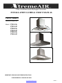
1
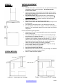
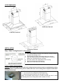
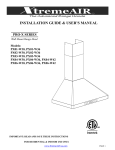
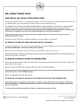
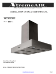
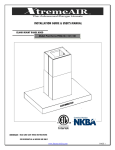
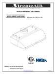
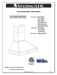
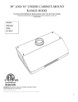
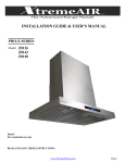
INSTALLATION GUIDE & USER’S MANUAL PRO-X SERIES Island Mount Range Hood Model: PX01-I36 PX01-I42 PX04-I36 PX04-I42 PX05-I36 PX05-I42 IMPORTANT: READ AND SAVE THESE INSTRUCTIONS FOR RESIDENTIAL & INDOOR USE ONLY www.XtremeAirUsa.com PAGE 1 TABLE OF CONTENTS 1 IMPORTANT SAFETY INSTRUCTIONS………………………………………………………..2-3 2 HEIGHT & CLEARANCE REQUIREMENT………………………………………………..……4 3 VENTING REQUIREMENT……………………………………………………………….…….…4 4 VENTING METHODS………………………………………………………………………………4 5 ELECTRICAL REQUIREMENT……………………………………………………………….….5 6 TOOL NEEDED……………………………………………………………………………………..5 7 PART SUPPLIED………………………………………………………………………….……….5 8 RANGE HOOD DIMENSIONS………………………………………………………………...….6 9 INSTALLATION………………………………………………………………………………..…..6-9 10 RANGE HOOD OPERATION……………………………………………………………..…...…9-10 11 SPECIFICATION………………………………………………………………….…….………….10 12 REPLACING THE LIGHT BULB……………………………………………….………………...11 13 TROUBLE SHOOTING………………………………………………………………….…....……11 14 USE & CARE………………………………………………………………….………….……...…12 15 WARRANTY…………………………………………………………………….…………………..13 IMPORTANT SAFETY INSTRUCTIONS IMPORTANT NOTICE: The Important Safety Instructions and warnings in this manual are not meant to cover all possible problems and situations that can occur. Please also use common sense and caution when installing, maintaining or operating this or any other appliance. Please always contact the XtremeAir USA, LLC. Customer Support Team at 1-714-554-9000 or email: [email protected] with any problems or situations that you do not understand. The manufacturer disclaims all liability for any damage or injury caused as a result of not following instructions for installation contained in the following text. DANGER To avoid the possibility of explosion or fire, do not store or use combustible, flammable or explosive vapors and liquids (such as gasoline) inside or in the vicinity of this or any other appliance. Keep items that could explode (such as aerosol cans) away from cook top burners, ovens and range hoods. Do not store flammable or explosive materials in adjacent cabinets or surrounding areas. Disclaimer: The manufacturer and/or distributor/reseller decline all responsibility in the event of failure to observe the instructions provided for installation, maintenance and suitable use of the product. The manufacturer and/or distributor/reseller shall NOT be responsible for any injury due to negligence and the warranty of the unit shall automatically be voided due to failure to observe proper safety and installation procedures. The manufacturer and/or distributor/reseller will not be held responsible for any damages to personal property or real estate or any bodily injuries whether caused directly or indirectly by the range hood. www.XtremeAirUsa.com PAGE 2 IMPORTANT SAFETY INSTRUCTIONS-continue WARNING - TO REDUCE THE RISK OF FIRE, ELECTRIC SHOCK, OR INJURY TO PERSONS, OBSERVE THE FOLLOWING: Use this unit only in the manner intended by the manufacturer. If you have questions, contact the manufacturer PRODUCT: Do not remove permanently affixed labels, warnings, or plates from the product. This may void the warranty. Do not try to alter the hood INSTALLATION: The installation in this manual is intended for qualified installers, service technicians or persons with similar qualified background. Installation and electrical wiring must be done by qualified professionals and in accordance with all applicable codes and standards, including fire-rated construction. When cutting or drilling into wall or ceiling; do not damage electrical wiring and other utilities. Due to the size and weight of this range hood, two people installation is recommended. Range hood may have very sharp edges; please wear protective gloves if it is necessary to remove any parts for installing, cleaning or servicing. VENTTING: For kitchen range or cook top ventilating use only. DO NOT use to exhaust hazardous or explosive materials and vapors. Ducted fans MUST always be vented to the outdoors. DO NOT vent exhaust into spaces between walls, crawl spaces, ceiling, attics or garages. Use only metal ductwork. Old duct work should be cleaned or replaced if necessary to avoid the possibility of a grease fire. Check all joints on duct work to insure proper connection and all joints should be properly taped. ELECTRICAL: All electrical wiring must be properly installed, insulated and grounded. Before servicing or cleaning unit, turn power OFF and un-plugged OPERATION: Use high settings on cooking range only when necessary. Keep all fan, baffle, spaces, filter, grease tunnel, oil container and grease-laden surfaces clean. Grease should not be allowed to accumulate on fan, baffle, spaces, filter, grease tunnel, and oil container. Never allow the filters to become blocked or clogged. Do not allow foreign objects, such as cigarettes or napkins, to be sucked into the hood. WARNING: TO REDUCE THE RISK OF A RANGE TOP GREASE FIRE: ■ Never leave surface units unattended at high settings. Boilovers cause smoking and greasy spillovers that may ignite. Heat oils slowly on low or medium settings. ■ Always turn hood ON when cooking at high heat or when greasy food. ■ Clean ventilating fans frequently. Grease should not be allowed to accumulate on fan or filter. ■ Use proper pan size. Always use cookware appropriate for the size of the surface element. WARNING: TO REDUCE THE RISK OF INJURY TO PERSONS IN THE EVENT OF A RANGE TOP GREASE FIRE, OBSERVE THE FOLLOWING: ■ SMOTHER FLAMES with a close fitting lid, cookie sheet, or metal tray, then turn off the burner. Be careful to prevent burns. If the flames do not go out immediately, EVACUATE AND CALL THE FIRE DEPARTMENT. ■ NEVER PICK UP A FLAMING PAN - you may be burned. ■ DO NOT USE WATER, including wet dishcloths or towels - a violent steam explosion will result. ■ Use an extinguisher ONLY if: – You know you have a class ABC extinguisher, and you already know how to operate it. – The fire is small and contained in the area where it started. – The fire department is being called. – You can fight the fire with your back to an exit. www.XtremeAirUsa.com PAGE 3 HEIGHT & CLEARANCE VENTING METHODS: VENTING REQUIREMENT IMPORTANT: • NEVER exhaust air or terminate duct work into spaces between walls, crawl spaces, ceiling, attics or garages. All exhaust must be ducted to the outside. • Hood mounted too low could result in heat damage and fire hazard; while hoods mounted too high will be hard to reach and will loose its performance and efficiency. • Use metal duct work only. Rigid metal vent is recommended. A minimum of 6” round (standard for this range hood, purchased separately must be used to maintain maximum airflow efficiency • DO NOT use plastic vent. • DO NOT use 4” (10.2 cm) laundry-type wall caps • Fasten all connections with sheet metal screws and tape all joints with aluminum tape. • Use caulking to seal exterior wall or roof opening around the cap. • The vent system must have a damper. If roof or wall cap has a damper, do not use damper supplied (for some models only) with the range hood. For the most efficient & quiet operation: • A distance of 26” to 30” is recommended between stove top and the bottom of range hood. • It is recommended that the range hood be vented vertically through the roof through 6” or bigger vent work. • ALWAYS, when possible, reduce the number or transitions and turns. If long duct run is required, increase duct size from 6” to 7” or 8”. If a reducer is used, install a long reducer instead of a pancake reducer. Reducing duct size will restrict airflow and decrease airflow, thus reduce duct size as far away from opening as possible. • If turns or transitions are required: Install as far away from opening and as far apart, between 2, as possible. • The size of the vent should be uniform. • Use no more than three 90° elbows. • Make sure there is a minimum of 24” (61 cm) of straight vent between the elbows if more than one elbow is used. • DO NOT install two elbows together. www.XtremeAirUsa.com PAGE 4 ELECTRICAL REQUIREMENTS: IMPORTANT: Observe all governing building codes and city ordinances. ■ A 120 volt, 60 Hz., AC only, 15-amp, fused electrical circuit is required. It is the customer’s responsibility: • To contact a qualified electrical installer. • To assure that the electrical installation is adequate and in conformance with National Electrical Code, ANSI/ NFPA 70 — latest edition*, or CSA Standards C22. 1-94, Canadian Electrical Code, Part 1 and C22. 2 No. 0M91 - latest edition** and all local codes and ordinances. TOOL YOU WILL NEED: Maker or pencil Stud finder Measuring tape Powered screwdriver or drill Flat & Phillips screwdrivers Level Drill with 1¼" , 1/4" (7.9 mm) drill bits Jigsaw or keyhole saw Cabinet Jack (optional) PARTS SUPPLIED: GREASE TUNNEL. NOT FOR PX04-I BAFFLE FILTERS (NOT FOR PX04-I MODEL) www.XtremeAirUsa.com PAGE 5 HOOD DIMENSION PX01-I36, PX01-I42 PX05-I36, PX05-I42 INSTALLATION PX04-I36, PX04-I42 Step 1: Mark “Ceiling Bracket” on the ceiling. 1. Put a thick, protective covering over counter top, cook top or range to protect from damage or dirt. 2. Find and mark the center point directly above your cook top 3. Place the ceiling bracket on the ceiling around the center point. (Make sure it is square with your cook top). 4. Trace the outline of the ceiling bracket onto the ceiling 5. Trace a circle where the ducting will go 6. Mark the 4 corners where you will screw. STEP 2: Install ceiling bracket Important: Due to the weight and size of this unit, ceiling bracket must be mounted to a weight-bearing ceiling (support system or framework being used is stable and secure on the ceiling) able to support at least twice the weight of the hood 1. Place chimney bracket against ceiling and screw into place 2. Cut out a hole in the ceiling where the ducting will go. 3. Drop the ducting and electrical work through the ceiling NOTE: Use threaded drywall anchors only when mounting the hood on sheet rock. Mounting the hood on ceiling rafter studs or lumbers is a must. www.XtremeAirUsa.com PAGE 6 STEP 3: Install support brackets 1. Attach multiple hoses brackets vertically outside the 4 corner of the ceiling bracket as show in Figure 3A. Figure 3A 2. Attach brackets vertically inside of the 4 multiple holes brackets installed in previous step (3A). Note: make sure extend the brackets to the appropriate length. (the bottom of the hood should be 26”-30” above the cook top) STEP 4: Install Chimney Important note: first make sure your ductwork is pulled down about 6 inch longer than the chimney 1. Slide inner and outer chimney sleeve over support brackets, covering the ceiling bracket 2. Screw inner chimney into place at the top of ceiling bracket 3. Lift the outer chimney all the way up to ceiling, USE screw driver to hold it from falling down Note: To avoid scratching the chimney, extend the inner upper chimney slowly and carefully to the chimney-mounting bracket .STEP 5: Attach Hood Body MODEL PX04-I36, PX04-I42, PX05-I36, and PX05-I42 – SKIP THIS STEP Mount the canopy glass to the hood. www.XtremeAirUsa.com PAGE 7 1. Have a third person raise up and hood the island range hood in position which is directly under the support brackets. 2. , connect power plug, and connect the ductwork to the range hood. HINT: Due to the heavy weight of this range hood, use vertical jack to lift and hold the hood in place is highly recommend it. 3. Screw hood to the support brackets on all 4 corners as show 5A STEP 6: Drop down outer Chimney 1. 2. hold outer chimney and remove the screw driver Slightly drop outer chimney down until it perfectly sits on the hood body. Note: To avoid scratching the chimney, extend the inner upper chimney slowly and carefully to the chimneymounting bracket. STEP 7: Install oil tunnel & baffle filters 1. PX01-I36 & PX01-I42 A. DROP OIL TUNNEL: INTO THE INSIDE HOOD BODY SLOT. REFER TO LEFT FIGURE B. INSTALL BAFFLE FILTERS; refer to Figure on the left for the following three steps: 1. Angle baffle filter toward front of hood (make sure opposite side of the slot.) 2. Lift a baffle filter up above horizontal level. 3. Slide forward into slot behind the other front of hood. To remove the baffle, please reverse the process. 2. BAFFLE FILTERS: . www.XtremeAirUsa.com PAGE 8 2. PX05-I36 & PX05-I42 RANGE HOOD OPERATION A. DROP 2 OIL TUNNELS: INTO INSIDE HOOD BODY SLOT AT BOTH ENDS. REFER TO LEFT FIGURE B. INSTALL BAFFLE FILTERS; refer to Figure on the left for the following three steps: 1. Angle baffle filter toward side end of hood 2. Lift a baffle filter up above horizontal level. 3. Slide forward into slot. To remove the baffle, please reverse the process. RANGE HOOD OPERATION NOTE: For best results, start the range hood before cooking and allow it to operate several minutes after the cooking is completed to clear all smoke and odors from the kitchen. Button functions: (1): To power ON/OFF the range hood, and to activate power-off delay timer. (2) To decrease blower (motor) speed, decrease timer value, and enter timer mode. (7) To increase blower (motor) speed, increase timer value, and cumulative timer reset. (3) Lights up when blower (motor) is running. (4) Shows current blower (motor) speed (1-4). (5) Lights up when lights turned on. (6) To turns ON/OFF lights. (8) Indicates the accumulated time the system is running. (9) Indicates the length of time left for delay off function. (10) Lights up when auto-shutdown delay timer function is on. A. Adjusting the blower (motor) speed: 1. Touch (1) Power button once - to turn on the system (The Blower Power Indicator icon flashes showing that the blower (motor) is ready) www.XtremeAirUsa.com PAGE 9 2. Decrease Value button will decrease the speed of the blower (motor) from 4 to 1 (strongest to quietest). Increase Value button will increase the speed of the blower (motor) from 1 to 4 (quietest to strongest). Touch Power button once to turn off the system. Note: The system saves user configurations, settings such as light, timer and blower (motor) speed will remain the same the next time it is turned on. B. To turn the light on: 1. Touch Light button once to turn on the lights, and once again to turn off the lights. C. Adjusting the timer function: 1. While the blower (motor) is not running, touch and hold Decrease Value button over 3 seconds to enter timer mode. 2. Adjust to desired period of delay off timer by touching Increase Value or Decrease Value button (minimum 1 minute to maximum 15 minutes). This setting will be saved immediately. D. Activating the timer function: 1. While the blower (motor) is running, touch and hold Power button for over 3 seconds to activate delay off timer. Power-off delay indicator will lit up and power-off delay digital timer will begin to countdown, when it reaches zero, the blower (motor) will shut down. E. To clear cleaning reminder: • When blower (motor) starts to rotate, cumulative running time will be shown in Power-On Elapsed Digital Timer. This timer icon flashes when 30 hours is up and reminds user to clean the baffle filters. • After cleaning the filters and when the motor is not in use, touch and hold (+) Increase Value button over 3 seconds to reset the timer. Please note that turning off the system will not reset the Power-On Elapsed Digital Timer. F. AUTOMATIC SHUT OFF: • MACHINE WILL AUTOMATICLY SHUT OFF AFTER OF APP. 2 ½ HOURS (FOR THOSE MANUFACTURED AFTER AUGUST 2012 ONLY) SPECIFICATION: Body Design Power Rating General Input Power Non-Magnetic 1.0 mm Stainless Steel, Satin Finish 120V/60Hz (USA & Canada standard) 154W (150W + 2x2W) Motor Input Power Ampere Levels Of Speed Control Maximum Airflow Noise Level Number Of Motors Motor Type Fan Type Filtration Type Illumination Venting Size Interference Protection 150 W each 1.3 A 4 Levels 900CFM Approximately 0.7 Sone(35dB) to 6.5 Sone (67dB) (Lowest to Highest Speed) Single Motor Single Chamber Ultra Quiet Squirrel Cage Heavy Duty Stainless Steel Baffle Filter LED light, 2W Maximum Top 8 inches Round Radio Frequency Interference Protected Specification subject to change without notice, contact your local reseller for details. Note www.XtremeAirUsa.com PAGE 10 REPLACING THE LIGHT BULB 1. Make sure the range hood is unplugged or turn OFF breaker. 2. Use the small flat crew driver to lift any where around the outsider ring as show in below picture Arrow. 3. Install new light bulb 4. Put back the light set by press it in. 5. Turn ON breaker and range hood to test for operation. TROUBLE SHOOTING 1. If the range hood or lights do not operate after installation: • • 2. The range hood vibrates when the blower is on: • • • 3. The blower or fan seems weak: • • 4. The lights work but the blower is not spinning at all, is stuck or is rattling. • • • 5. The hood is not venting out properly: • Check if the range hood has been plugged in, make sure that all power has been turned back ON, the fuse is not blown and all electrical wiring is properly connected. Swap out light assembly to working ones to determine whether it is caused by defective bulbs. See replacing the light bulbs on Page 10. The range hood might not have been secured properly on to the ceiling. Check if the motor is secured in place. If not, then tighten the motor in place. Check if the blower wheel is a damaged. Check that the duct sized used is at least 6”. Range hood WILL NOT function efficiently with insufficient duct size & loosely secured. Check if duct is clogged or if damper unit (half-circular flapper) is not installed correctly or opening properly. A tight mesh on a side wall cap unit might also cause restriction to the air flow. The blower might be jammed or scraping the bottom due to shipping damage. Please contact us immediately. The motor is defective, possibly seized - change the motor. Electronic board might have errors • Make sure the distance between the stove top and the bottom of the hood is within 26” and 30” in distance. Due to different ceiling height configurations, recommended height may not be applicable. Reduce the number of elbows and length of duct work. Check if all joints are properly connected, sealed, and taped. Make sure the power is on high speed for heavy cooking • The duct is not secure cause variation • The wrong duct size is using 7. Control panel is not active • Check to make sure the auto function is not on 8. Remote control is not working • Check to make sure the plastic film was removed. • 6. The hood is noisy than normal www.XtremeAirUsa.com PAGE 11 USE & CARE INFORMATION: Operations: • Read and understand all instructions and warnings in this manual before operating the appliance. Save these instructions for future reference. • Always leave safety grills and filters in place. Without these components, operating blowers could catch on to • hair, fingers and loose clothing. • NEVER dispose cigarette ashes, ignitable substances, or any foreign objects into blowers. • NEVER leave cooking unattended. When frying, oil in the pan can easily overheat and catch fire. The risk of self combustion is higher when the oil has been used several times. • NEVER cook on “open” flames under the range hood. Check deep-fryers during use: Superheated oil may be flammable. Cleaning: • The saturation of greasy residue in the blower and filters may cause increased inflammability. Keep unit clean and free of grease and residue build-up at all times to prevent possible fires. • FILTERS MUST BE CLEANED PERIODICALLY AND FREE FROM ACCUMULATION OF COOKING RESIDUE. Old and worn filters must be replaced immediately. • DO NOT operate blowers when filters are removed. Never disassemble parts to clean without proper instructions. Disassembly is recommended to be performed by qualified personnel only. Read and understand all instructions and warnings in this manual before proceeding. MAINTENANCE: SAFETY WARNING: Never put your hand into area housing the fan while the fan is operating! For optimal operation, clean range hood and all baffle/spacer/filter/grease tunnel/oil container regularly. Regular care will help preserve the appearance of the range hood. Cleaning Exterior surfaces: • Clean periodically with hot soapy water and clean cotton cloth. Do not use corrosive or abrasive detergent (e.g. Comet Power Scrub®, EZ-Off® oven cleaner), or steel wool/scoring pads, which will scratch and damage the stainless steel surface. For heavier soil use liquid degrease such as “Formula 409®” or “Fantastic®” brand cleaner. • If hood looks splotchy (stainless steel hood), use a stainless steel cleaner to clean the surface of the hood. Avoid getting cleaning solution onto or into the control panel. Follow directions of the stainless steel cleaner. CAUTION: Do not leave on too long as this may cause damage to hood finish. Use soft towel to wipe off the cleaning solution, gently rub off any stubborn spots. Use dry soft towel to dry the hood. • After cleaning, you may use non abrasive stainless steel polish such as 3M ® or ZEP®, to polish and buff out the stainless luster and grain. Always scrub lightly, with clean cotton cloth, and with the grain. • DO NOT allows deposits to accumulate or remain on the hood. • DO NOT use ordinary steel wool or steel brushes. Small bits of steel may adhere to the surface and cause rusting. • DO NOT allow salt solutions, disinfectants, bleaches, or cleaning compounds to remain in contact with stainless steel • for extended periods. Many of these compounds contain chemicals, which may be harmful. Rinse with water after exposure and wipe dry with a clean cloth. Cleaning Aluminum Grease Filter / Stainless Steel Filter less Grill: IMPORTANT: Drain oil from oil containers before oil and residue overflow! • The metal filters fitted by the factory are intended to filter out residue and grease from cooking. It need not be replaced on a regular basis but are required to be kept clean. • Filters should be cleaned after every 30 hours of use. • Remove and clean by hand or dishwasher. Spray “Formula 409®” or equivalent degreasing detergent and leave to soak if heavily soiled. Dry filters and re-install before using hood. Replacing Filters: • Should filters wear out due to age and prolonged use, please contact your local reseller for replacement filters. Note: Also replace damaged filter that has punctured or broken mesh, bent or broken frame. . www.XtremeAirUsa.com PAGE 12