1
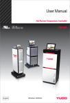
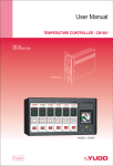
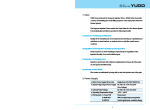
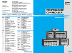
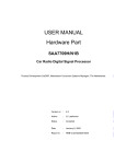
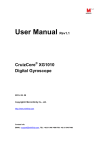
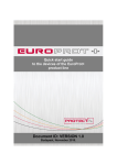
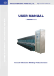
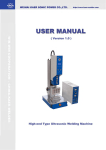
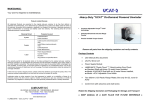
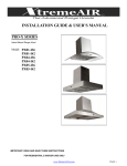
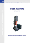
English
CW 991
(72 Zone)
CW 991
(24 Zone)
CW 662
(18 Zone)
Temperature controller
&
Sequence timer
TW 700
(8 Zone)
TW 600
(8 Zone)
CW 991
High precision
High precision (±0.01℃), high reliable hardware
Multi zone
Multi zone configurations (Max. 240 zones, 6 zones / unit)
Networking
Remote control based on standard MODBUS-RTU
Easy use
User friendly touch panel equipped with HMI(Human-machine interface).
A quick and easy way to manage process parameters
Integrated sequential valve gate control and hot runner control
Data management
Easy data management to store and manage files in folders
Self-diagnostics
(Ground fault, Triac short, Heater Open/Short, Sensor reverse,
Sensor burnout, RJC, ADC, Fuse, AC)
Features
- Easy additional zone installation
- Quick Auto Tuning for fast heat-up
- Auto- recognition for operating zone
- Select individual, designated or all zone(s)
72 Zone
- Auto-detection for a type of sensor
24 Zone
- Manually open the designated all gates
TEMPERATURE CONTROLLER
Principal function
Mold control data management
It provides easy control by saving and managing desired parameters.
(Capacity 12G, Min. over 10,000 items)
Can save information on mold control. (Model, Photo, Hot runner Image, Date)
Sequence control / cascade
Sequential valve gate control timer function is added to CW 991 for the integrated
hot runner control. (Max. 12 outputs)
3 modes are preprogrammed. (Mode A / B / C)
Error log
Error messages are saved automatically if error occurs. (Max. 5,000 messages)
Data can be saved and synchronized from Main PC to USB.
System diagnosis (Mold test)
The controller has a diagnostic testing tool, which allows you to check that every zone
correctly operates. (Wiring, automatically correct T/C poles in case of reverse T/C, excessive current check, etc.)
User friendly data setting
The processor can easily set all data for control. (User and manager login mode)
Easy monitoring for data setting and remote control are available.
Help (Interface)
User manual is embedded in the panel PC for easy use.
Language - English (Option available for multi languages)
Precise control
- CW 991 automatically conducts auto tuning when
controlling heater temperatures, and controls
temperatures precisely and stably.
(Precision : within ±0.1℃)
- No more over shooting problem during heating up.
(within 1℃ / less than 1 times)
- Excellent response time offers fast and precise
temperature control when changing the target
temperatures. (Frequency : 100 ms)
- CW 991 interacts with ambient temperature.
It's best solution for high temperature molds.
(steam mold, electric heat mold, etc)
A variety of applications
- It precisely controls and performs great, especially with
sensitive heaters such as ultra mini heater.
- It can precisely control sensitive heaters.
- Control range : 0 ~ 500℃ (Option available for 999℃)
250.6
Steady state
250
249.4
CW 991 TEMPERATURE TEST (250℃)
300
Control performance graph
250
200
Temp.
Precise temperature control
150
100
50
0
0
100
200
300
400
500
600
Time (Seconds)
700
800
900
1000
CW 991
Temperature display
Text view
·The data is displayed as text values.
·This screen allows you to view target and actual temperatures, output rates and
currents of heaters. Furthermore, it allows you to change data setting values.
Bar chart view
·The data is displayed in a graphical format.
·This screen allows you to view target and actual temperatures, output rates and
currents of heaters.
·Switch on or off individual zone by touching bar graph.
Picture view
·The data is displayed in an image format.
·This screen allows you to add and delete user selected zones on the image.
Digital view
·The data is displayed in grid format.
·To change the data setting from Basic Setting Screen by touching individual grid.
Sequence timer [Optional timer]
Timer setting screen
·To change sequential mode and display a unit of 12 output Sequence Injection timer.
·To open or close each valve gate individually to precisely control the material flow front.
·To manually open or close the selected valve gates or all valve gates at the same time.
Mode A
Mode B
Gate open
T
t1
Signal on
Gate open
Gate open
T
t2
3 sec
Mode C
10 sec
Signal off
t1
Signal on
T
t2
3 sec
10 sec
Signal off
t1
t2
3 sec
Signal on
Gate open
t3
7 Sec
t4
12 sec
18 sec
20 sec
Signal off
t1 : Delay 1 time / t2 : Open 1 time / t3 : Delay 2 time / t4 : Open 2 time
TEMPERATURE CONTROLLER
Dimensions
24 zone
380
300
615
48 zone
72 zone
96 zone
120 zone
577
345
699
467
842
610
972
740
72
96
120
48
24
570
508
CW 991
CW 991
CW 991
CW 991
CW 991
Model
CW 991
Cabinet sizing
Max. capacity
Remarks
12 - 24 Zone
100A
·7 inch wide touch panel / Optional 12 output sequence timer.
28 - 48 Zones
100A
·12 inch touch panel / Optional 8 output sequence timer.
54 - 72 Zones
150A
78 - 96 Zones
150A
102 - 120 Zones
225A
1550
1515
1230
1380
CW 991
·15 inch Touch panel / Optional 12 output sequence timer.
Specifications
HMI
Display console
Input device
Language
Power
12, 15" TFT Monitor (24 Zone - 7" wide)
4 wire resistive touch panel
English
Input
Voltage
Frequency
Consumed power per cabinet configuration
3 phases 4 lines 380V, 3 phases 3 lines 220V
50/60Hz
154W,175W, 217W, 260W, 315W (24, 48, 72, 96, 120 Zone - 220VAC)
Data communication
6 Zone/Unit
Thermocouple TC-K, TC-J (IEC-584)
0.0 ~ 500.0 ℃ (32~932℉)
100 ms
± 0.5 % of F/S
0.1 ℃ (0.18℉)
± 2.0 ℃ (-15 ~ 65℃)
Protocol
Max. number of connection
Zone
Output mode
Output resolution
Max. admissible current
6 Zone / Unit
Phase control, Zero cross control
Phase control : 1,000 Res. Zero cross control : 120 Res. (60Hz), 100 Res. (50Hz)
15A / Zone, 50A / Unit(6 Zone)
Input
Injection signal
Voltage
24 VDC
110 VAC, 220 VAC
Output
Relay
Period of renewal
1 sec.
24VDC (Max. 100mA) x 12 outputs (valve gates)
110VAC (Max. 1A) x 12 outputs (valve gates)
220VAC (Max. 1A) x 12 outputs (valve gates)
System rule
Mode
Zone
Sensor type
Control range
Scan rate
Scan accuracy
Display resolution
Compensable temperature variation
Output
About within 1.2 km (depending on the installation environment)
Sequence timer [Optional timer]
Environment
Operating temperature
Operating humidity
Storage temperature
Insulation resistance
Withstand voltage
Vibration resistance
Impact resistance
Magnetic effect
Warming-up time
Communication method
Communication speed
Port parameter
Communication distance
EIA-RS485/422, USB V2.0 (HOST, SLAVE)
Max. 21 IDs (include master)
Repeater is required if additional IDs are connected.
Half- duplex 2 wire
19,200 bps
NONE PARITY, 8 DATA, 1 STOP BIT
0 ~50℃ (32~932℉)
20 ~ 90% RH (NO condensing)
-25 ~ 70℃ (~158℉)
500VDC, Over 20MΩ (Input power-field ground, Input/Output-field ground)
1,500Vac 50/60Hz 60sec (Input power-field ground, Input/Output-field ground)
10 ~ 55Hz, Bandwidth 0.75mm, 3directions 4swings, 5min/swing
147㎨, 3directions 3times
Below 400 AT/m
Over 30 min
Misc.
Mode A : Set delay 1 time
Mode B : Set delay 1, Open 1 times
Mode C : Set delay 1, Open1, Delay 2, Open 2 times
Setting time unit : 0.00 ~ 999 sec.
Independent running.
Detect and display solenoid value output voltage.
Open all valve gates or individual valve gate.
※ CW 991 48 zone model use 8 outputs sequence timer instead of 12 outputs sequence timer.
CW 662
High precise temperature control
1)
High speed auto tuning
Precise control by stable ‘PID Control Algorism’
High resolution
2)
High resolving power and high speed Delta-Sigma AD converter
High reliability
3)
High reliable hardware design
Protection
Preventing from triac damage
Detecting over-current and inspecting ground fault
Error code saving
Detecting *16 different error and saving
*(Sensor disconnection, Sensor polarity reverse, Heater disconnection, Heater short-circuit,
Triac short-circuit, Ground fault detection, Fuse 1 breakdown, Fuse 2 breakdown, Fuse 1/2 breakdown,
High limit alarm, Low limit alarm, Frequency alarm, CT, RJC, ADC,Corrective alarm)
Features
1) - Optimal speed control in any type of heater
(From low voltage nozzle to high capacity manifold)
- Quick tuning & Full tuning
2) - High precise measurement within ±0.01℃
- Quick response by implement high speed sampling
3) - High-brightness LED with uniform and broad visibility
- Shutdown input power in the case of over voltage
- Apply surge protector (3,600 Vac)
- Accurate current detection using high precise CT (±0.2%)
- Stable system with better external noise tolerance
TEMPERATURE CONTROLLER
Principal function
Precise temperature control
· It provides high precise measurement within ±0.01℃ and operation to control temperature stably.
Standby function
· This function is to control the output power by setting values in case of production pause
for a while when the setting time is up, it recovers the original value.
Soft-Start
· When power on, this function protects heaters from excessive output.
· Soft-Start helps heaters to prevent humidity-caused and over-current-caused damage by slow preheating.
Manual temperature calibration function
· This is a function to compensate the temperature at the setting mode by manual in case of
abnormal difference between PV and SV temperatures.
Parameter protection function
· This security feature helps to prevent accidental changes to parameter settings.
Thermocouple failure indication
· Alows users to check the type and status of thermocouple.
· When thermocouple disconnected or polarity reversed during the operation, the operation
automatically terminates the output.
Heater failure indication
· In case of short-circuit & disconnection over-current, it shows error signs and terminate the output.
Algorism
Temp.
Approx. ‘0’ Overshoot
200
CW 662
150
‘A’ Company
100
200.4
200.2
200.0
199.8
199.6
50
Soft-Start time
Auto-Tuning time
PID control time
0
Time
CW 662
Hardware upgrade
2
1
1
5
4
Relay
Heat-sink
3
2
Fuse holder
4
Triac
3
1. Heat-sink plate
- High capacity heat-sink plate prevents triac damage by heat.
2. Ground fault self-inspection
- This function is to protect heaters and operators by automatically stopping over-current resulted from a short circuit.
- Relay can automatically stop leaked current to protect controller's electric circuit in case of emergency.
3. Fuse
- Fuze holder application - minimizing fuze breakdown by isolating contact resistance rise.
- 32bit CPU application - minimizing fuze breakdown by stopping over-current spontaneously.
4. Triac
- High capacity triac(30A) application - minimizing triac damage caused by over-current.
5. Display
- Bright and uniform display and broaden visibility with high-brightness LED
- Thermocouple type (IC/CA) display
- Temperature symbol display (℃, ℉)
5
Main frame
Air in
Filter
Fan
Air out
Unit
1. CW 662 main frame achieves high durability to protect the control
module, by double cell structure.
2. The new frame achieves high quality air ventilation system.
3. A PET filter is installed to the ventilation holes to clean the
circulation air.
4. Reinforced guide rail in the frame ensures the control module
mounted in the frame smoothly and rigidly.
5. The material of filter : PET
Thickness : 10mm
Heat resistance : 100℃
Capacity of filter : 70
TEMPERATURE CONTROLLER
Mode parameters
Mode parameters can be selected according to the operating conditions.
PV FND
Description
AL-L
SV panel
Feasible range
Factory-set
Low process temperature alarm
± 99
0℃
AL-H
High process temperature alarm
± 99
0℃
Unit
Calibration of temperature
0 / 0.0
0
Users set standby time
St_t : 0~23h 59min
St_t : 1.00(1h)
Users set standby temperature
StSV : 0~400℃
StSV : 0~50℃
CdsP / FdsP
Users selects temperaure unit (℃ or ℉)
Cdsp, Fdsp
Set by, Customer order
LoCK
It prevents accidental or unauthorized changes to parameter settings.
On, Off
Off
Stby
Dimensions
Max. capacity
30A
178
300
400
500
2 zone
4 zone
6 zone
8 zone
18 zone
24 zone
Remarks
·
50A
100A
325
235
Cabinet sizing
2 Zones
4 Zones
6 Zones
8 Zones
12 Zones
16 Zones
18 Zones
24 Zones
·Stand
(Optional)
150A
500
12 zone
16 zone
468
700
400
Specifications
Free voltage 100V ~ 240 V(50 / 60 Hz)
Thermocouple type
TC-K (IEC-584), TC-J (IEC-584)
Calibration of temperature
± 0.5 % of F/S
Output mode
Phase angle control, Zero cross control
Capacity
15A(Max 16.5A), 1 zone/Unit
Ambient temperature range
0 ~50℃ (32~122℉)
Humidity
20 ~ 90% RH
Temperature control method
PID control
Approved
CE UL/cULus
590
Input voltage
CW 662 Stand
(Optional)
500
650
TW 600 & TW 700
Removal or re-positioning of weld line.
Control of the injection volume by gate operation time.
Improvement on flash and short-shot.
TW 700 - Pendant type timer
Features
TW 700 (8 Zone)
- Simultaneous control on the max. 8 gates.
- Simple operation to change the value and setting time.
- Display the solenoid valve output voltage.
- Support various operating modes on each gate. (MODE A / B / C )
- Display the working condition on a real-time basis.
- Setting-data memory function in a power-off status.
- Software power on/off application.
- Manual on/off control function on each or all gate.
- Solenoid valve output voltage AC220V, DC24V available.
(pneumatic solenoid only)
- Precise time control. (Min 0.01sec. ~ Max 999sec.)
- Initialization function.
- Smart and solid design.
Specifications
Supply voltage
1 Phase AC(100 ~ 250VAC), 50/60Hz
Voltage bandwidth
Stable within ±20% supply voltage swing
Supply earth-leakage trip
10mA per individual zone ground fault monitoring (note: this is for tool protection)
Consumption current (idle state)
Max. 11VAC
Injection signal input voltage
DC24V, AC220V (Free voltage)
Display resolution limit
0.01sec
No. of zones
8 zones
Relay output mode
Relay arbeit contact
Output (solenoid) capacity
2.5A @ DC24V (1A @ AC220V)
Output (solenoid) voltage
DC24V, AC220(Only for pneumatic solenoid)
(*AC solenoid valve output voltage is up to AC input power.)
Consumption current (solenoid)
Max 100mA per zone
Operating temperature
0~50℃ (32~122℉)
Operating humidity
0~90% R.H(Non-condensing)
SEQUENCE TIMER
TW 600 - Cartridge type timer
Features
- Simple operation to change the value and setting time.
- Display solenoid valve output voltage.
- On/Off function manual gate.
- Solenoid valve output voltage.
(Pneumatic : AC 220V / DC 24V [Hydraulic is optional])
- Support various operating modes. (MODE A / B / C )
- Display the working-condition on a real-time basis.
- Setting-data memory function on a power-off status.
- Precise time control application (Min 0.01sec. ~ Max 999sec.)
- Power on/off based on the software.
TW 600 (8 Zone)
Specifications
Main power supply (Timer case)
AC(85~264VAC),50/60 Hz
Injection signal input power
DC 24V, AC 110V, AC 220V (Free voltage)
Solenoid valve output voltage
DC 24V, AC110V, AC220V
*AC solenoid valve output must be same with AC input power .
0℃~ 50℃
Operating temperature
PCB structure
① Power board
Power PCB
② Relay board
Relay (Solenoid valve on/off)
③ CPU board
MPU, Out signal input/output, Display, Switch signal input
④ Front board
Solenoid valve output display (24V or 220V)
⑤ Mother board
DC main power distribution and connector
Mode operation (TW 700 & TW 600)
MODE C
MODE A
Gate open
t1
T Delay
time
t2
3 sec
10 sec
Signal off
Signal on
T
t1
Delay time
Gate open
t2
Open time
3 sec
7 sec
Gate open
t4
Open time
t3
Delay time
12 sec
18 sec 20 sec
Signal on
Signal off
MODE B
T
t1
Delay time
3 sec
Signal on
T
t1
Delay time
3 sec
Signal on
Gate open
t2
Open time
Injection signal extension function
10 sec
Signal off
Gate open
t2
Open time
T
t1
Delay time
3 sec
10 sec 12 sec
Signal off
Signal on
Gate open
t2
Open time
10 sec
12 sec
Signal off
(Machine)
Signal off
(Timer)
Global network
www.yudo.com
Any question? Access to http://qna.yudo.com
Germany
Germany
Portugal
Portugal
Italy
Spain
Poland
Slovakia
Romania
Turkey
Iran
Austria
Syria
Israel
Bangladesh
India
India
Egypt
China
Weihai
Qingdao
Thailand
Korea Japan
Tokyo
Suzhou
Nagoya
Kunshan
Suzhou
Taiwan
Dongguan
Hongkong
Malaysia
Vietnam
Headquarter
USA
Plant
Ohio
Subsidiary
Sales office
Agency
Singapore
Mexico
Peru
Indonesia
New Zealand
South Africa
Brazil
Australia
Click
Clip ANSWER
▶ We reserve the right to change specifications without notice.
UK
France
Finland
Ver.1.5 CON. (2011.Sep)
Netherlands
Czech