1
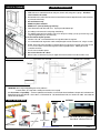
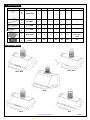
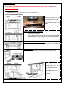
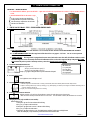
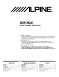
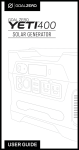
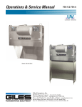
INSTALLATION GUIDE & USER’S MANUAL UNDER CABINET RANGE HOOD Pro-X Series: PX10-U30/36/42/48 PX11-U30/36/42 PX12- U30/36/42 Ultra Series: UL10- U30/36/42 UL11- U30/36/42 UL13- U30/36/42 Deluxe Series: DL09-U36/42/48 IMPORTANT: READ AND SAVE THESE INSTRUCTIONS FOR RESIDENTIAL & INDOOR USE ONLY www.XtremeAirUsa.com PAGE 1 TABLE OF CONTENTS 1 IMPORTANT SAFETY INSTRUCTIONS ......................................................................................................................... 2 2 HEIGHT & CLEARANCE ............................................................................................................................................ 3 3 VENTING REQUIREMENT .......................................................................................................................................... 3 4 VENTING METHODS ................................................................................................................................................. 3 5 ELECTRICAL REQUIREMENT ...................................................................................................................................... 3 6 TOOLS YOU WILL NEED............................................................................................................................................. 3 7 PARTS SUPPLIED ...................................................................................................................................................... 4 8 DIMENSIONS ........................................................................................................................................................... 4 9 INSTALLATION......................................................................................................................................................... 5-6 10 INSTALL & REMOVE BAFFLE FILTERS ......................................................................................................................... 6 11 RANGE HOOD OPERATION........................................................................................................................................ 7-9 12 SPECIFICATION ........................................................................................................................................................ 9 13 TROUBLE SHOOTING ................................................................................................................................................ 9-10 14 USE & CARE INFORMATION ...................................................................................................................................... 10 15 MAINTENANCE ........................................................................................................................................................ 10 16 PRODUCT WARRANTY .............................................................................................................................................. 11 1. IMPORTANT SAFETY INSTRUCTIONS IMPORTANT NOTICE: The Important Safety Instructions and warnings in this manual are not meant to cover all possible problems and/or situations that can occur upon installation of this unit. Use extreme caution when installing, maintaining or operating this or any other appliance. Contact the XtremeAir USA, LLC, Customer Support Team at 1.714.554.9000 or email: [email protected] with any concerns or situations that you do not understand. The manufacturer disclaims all liability for any damage or injury caused as a result of not following instructions for installation contained in this manual. DANGER To avoid the possibility of an explosion or fire, do not store or use combustible, flammable or explosive vapors and liquids (such as gasoline) inside or in the vicinity of this or any other appliance. Keep all combustible items (such as aerosol cans) away from cook top burners, ovens and range hoods. Do not store flammable or explosive materials in adjacent cabinets or surrounding areas. Disclaimer: The manufacturer and/or distributor/reseller decline all responsibility in the event of failure to observe the instructions provided for installation, maintenance and suitable use of the product. The manufacturer and/or distributor/reseller shall NOT be responsible for any injury due to negligence and the warranty of the unit shall automatically be voided due to failure to observe proper safety and installation procedures. The manufacturer and/or distributor/reseller will not be held responsible for any damages to personal property or real estate or any bodily injuries whether caused directly or indirectly by the range hood. WARNING - TO REDUCE THE RISK OF FIRE, ELECTRIC SHOCK, OR INJURY TO PERSONS, OBSERVE THE FOLLOWING: *Use this unit only in the manner intended by the manufacturer. If you have questions, contact the manufacturer. PRODUCT: Do not remove permanently affixed labels, warnings or plates from the product. This may void the warranty. Do not try to alter the hood. INSTALLATION: The installation in this manual is intended for qualified installers, service technicians or persons with a similar qualified background. Installation and electrical wiring must be provided by qualified professionals and in accordance with all applicable codes and standards, including fire-related construction. When cutting or drilling into the wall or ceiling; do not damage electrical wiring and other utilities. It is recommended that two or more people assist with the installation. The range hood may have very sharp edges; please wear protective gloves if it is necessary to remove any parts for installing, cleaning or servicing. VENTING: For kitchen range or cook top ventilating use only. DO NOT use units to exhaust hazardous or explosive materials and vapors. Ducted fans MUST always be vented to the outdoors. DO NOT vent exhaust into spaces between walls, crawl spaces, ceiling, attics and/or garages. Use only metal ductwork. Old duct work should be cleaned or replaced if necessary to avoid the possibility grease fires. Check all joints on ductwork to insure proper connections. All joints should be properly taped. ELECTRICAL: All electrical wiring must be properly installed, insulated and grounded. TURN POWER OFF and un-plug cords from outlet before servicing and/ or cleaning to insure your safety. OPERATION: Caution is suggested when using high settings on cooking range. Keep all fan, baffle, spaces, filter, grease tunnel, oil container and greaseladen surfaces clean. Grease should not be allowed to accumulate on fan, baffle, spaces, filter, grease tunnel, and oil container. Never allow the filters to become blocked or clogged. Do not allow foreign objects such as cigarettes and/or napkins, to be absorbed into the hood. Clean ventilating fans frequently. Grease should not be allowed to accumulate on the fan or filters. www.XtremeAirUsa.com PAGE 2 2. HEIGHT & CLEARANCE 3. VENTING REQUIREMENTS IMPORTANT: NEVER exhaust air or terminate ductwork into crawl spaces, between walls, ceiling, attics or garages. All exhaust must be ducted to the outside. Hood mounted too low could result in heat and/or fire hazard. Hoods mounted too high will be hard to reach and will lose its performance and efficiency. Use metal ductwork only. DO NOT use plastic ventilation. DO NOT use 4” (10.2 cm) laundry-type wall caps. Fasten all connections with sheet metal screws. Tape all joints with aluminum tape. Use caulking to seal exterior wall or roof openings around the cap. The ventilation system must have a damper. If the roof or wall cap has a damper, you may opt out from usage of your range hood supplied damper (for some models only). For the most efficient & quiet operation: A distance of 26” to 30” is recommended between stove top and the bottom of range hood. It is recommended that the range hood be vented vertically through the roof with a minimum of a 6” or larger vent work. ALWAYS, when possible, reduce the number or transitions and turns. If a long duct run is required, increase duct size from 6” to 7” or 8”. If a reducer is used, install a long reducer instead of a pancake reducer. Reducing duct size will restrict/decrease airflow. The size of the vent should be uniform. Use no more than three 90° elbows. Make sure there is a minimum of 24” (61 cm) of straight vent between the elbows if more than one elbow is used. 4. VENTING METHODS 5. ELECTRICAL REQUIREMENTS IMPORTANT: Observe all governing building codes and city ordinances. A 120 volt, 60 Hz., AC, 15-amp outlet is needed (fused electrical circuit is required) It is the customer’s responsibility: To contact a qualified electrical installer, to assure that the electrical installation is adequate and in conformance with National Electrical Code, ANSI/ NFPA 70 — latest edition*, or CSA Standards C22. 1-94, Canadian Electrical Code, Part 1 and C22. 2 No. 0-M91 - latest edition and all local codes and ordinances. 6. TOOLS YOU WILL NEED OPTIONAL Level Tape Measure Wall/Keyhole Saw Stud finder CAR JACK Powered Screwdriver Pencil or Marker Phillip Screwdriver Hex bit extension CABINET JACK (2) 2” x 4” x 24” (1) 24” x 36”/42” x ¾” plywood Note: about 6” wider than stove is ok Aluminum Tape www.XtremeAirUsa.com PAGE 3 7. PARTS SUPPLIED PART SKETCH CODE DESCRIPTION PX10 PX11 PX12 UL10 UL11 UL13 DL09 M B MANUAL BOOK 1 1 1 1 1 1 1 OIL TUNNEL 1 1 1 1 1 1 1 1 ¾ “ SCREW 2 2 2 2 2 2 4 1 ¼ “ SCREW 4 4 4 4 4 4 4 B F BAFLE FILTERS 3 3 3 3 3 3 3 (36” / 42 “) 4 (48”) R C REMOTE CONTROL 1 N/A 1 N/A N/A N/A N/A O T S 1 S 2 8. HOOD DIMENSIONS PX11 / UL11 PX10 / UL10 DL09 UL13 PX12 www.XtremeAirUsa.com PAGE 4 9. INSTALLATION NOTE: DO NOT TRY TO REMOVE BLOWER OR ITS HOUSING, YOU WON’T BE ABLE TO PUT IT BACK IN. MOREOVER, THE WARRANTY WILL BE VOIDED. STEP 1: PROTECT THE COOK TOP Put a thick, protective covering over counter top, cook top or range to protect from damage or dirt. STEP 2: CREATE WORK STATION (OPTIONAL) Have 2 pieces of wood about 2” x 4” x 20” on both sides of stove & a plywood on top of them to protect cook top or stove from damage or dirt. This plywood will also create a comfortable work station for easy to installing. STEP 3: PREPARE DUCTWORK & SINGLE OUTLET Make sure you have a 15amp, 120V, 60Hz, single outlet on the left or right of the duct pipe (usually is on ¼ of cabinet width). Make sure duct pipe is ready to hook up to the range hood before beginning installation (8” diameter duct, and roof or wall cap, depending on where you will be venting your hood). STEP 4: ATTACH 2-INCH WIDE WOOD FILLER STRIPS For installing under the cabinet with recessed bottom, attach 2-inch wide wood filler strips (not provided) to each side. STEP 5: CREATE ACCESS Create or cut access opening for electrical wire and hood exhaust under the cabinet STEP 6: ATTACH THE HOOD Lift the hood up and have it placed below the cabinet. Make sure to center the hood beneath the cabinet and flush with the front of the cabinet. TIP (optional): since the hood is heavy, a cabinet or a car jack is highly recommended. www.XtremeAirUsa.com PAGE 5 STEP 7A: SECURE THE HOOD TO BOTTOM CABINET D09 model: please skip this step if you don’t have cabinet above the hood. From inside of the hood, use “hex bit extension” place 1 ¼” provided screw into each key hole (A) OR predrilled-holes (B) and secure to cabinet bottom. There are 8 holes (4 keyholes & 4 predrilled-holes) available. You can use either key or predrilled-hole as long as a minimum of 1 screw at each corner of hood body. STEP 7B: SECURE THE HOOD TO WALL Use stud finder to find the stud and use 1/8” drill bit to drill though the back of the hood. Secure the hood by using 1 7/8” provided screws though the back of the hood to the studs. 10. Secure the hood by using 1 7/8” provided screws through the back of hood to the studs (use stub finder to find the stud. Figure 7 CAUTION: certain the range hood is secure before releasing! STEP 8: CONNECTMake DUCTWORK 11. Connect the exhaust theductwork. hood to thewith ductwork Useall joints Connect the exhaust on the hoodon to the Wrap aluminum above. tape to make aluminum tape to make all joints secure and all tight secure and tight. STEP 9: INSTALL OIL TUNNEL OR OIL CONTAINER (NOT AVAILABLE FOR ALL MODELS) Drop oil tunnel into recess support near rear of hood. Refer to the left picture Oil Tunnel Side View Step 10: Install baffle filters Install baffle filters; refer to picture at left for the following three steps: 1.Angle baffle filter toward back of hood. 2.Lift a baffle filter up above horizontal level. 3.Slide forward into slot behind the front of hood. 4.Slide the installed baffle filter to either left or right until it stops. 5.Repeat step 1 to 4 to install the next ones, make sure you slide to opposite direction from the previous installed filter. To remove the baffle, please reverse the process. NOTE: The middle filter has to be installed last where it should be taken out first when you want to remove other filters. . Baffle Installation Side View www.XtremeAirUsa.com PAGE 6 11. RANGE HOOD OPERATION IMPORTANT: BEFORE YOU BEGIN 1. For TOUCH SENSITIVE CONTROLS, please DO NOT PRESS. A light touch and hold on the required button for a matter of a (1) one second is all that is needed. CORRECT INCORRECT 2. TOUCH THE ENTIRE BUTTON: See illustration on right: For best results, Start the range hood before cooking and allow it to operate several minutes after the cooking is completed to clear all smoke and odors from the kitchen. VS. Entire button covered and lightly touched. Button is NOT completely covered. 1. FOR PX10 & PX12 Model: TYPE 1: TOUCH SCREEN CONTROL PANEL Importance Notice: 1. AUTO FUNCTION ACTIVE: Once “Auto Function” is on or touched, all other functions will be DE-ACTIVATED and will NOT be working. 2. 2 ½ HOUR AUTOMATIC SHUT OFF: This range hood will be shut off for every approx. 2 ½ hours. You can re-start operation usual after it was shut off. 3. SCREEN TURN OFF: This range hood is equipped with remote control and smoke sensor that will self-calibrate within 5 seconds when the range hood is first electrically activated. Self-calibration will be set when the range hood beeps. LCD panel WILL TURN OFF automatically after a period of inactivity and every time when plugged into electrical outlet. A. ACTIVATING NORMAL BLOWER FUNCTION: While the range hood is off, Touch (+) to start from lowest speed, F1 Touch (-) to start from Highest speed, F4 Touch (+) or (-) again to change the blower speed as indicated in LCD panel 00 = blower off F1 = quiet speed F2 = low speed F3 = medium speed F4 = high speed B. Activating Light Function: Touch Light button to turn the lights on or off. C. Activating Power-Off Delay Function: 1. While the range hood is on and the blower is running in normal mode, touch Power-Off Delay button to activate delay off timer. 2. Adjust to desired period of delay of timer by touching (-) or (+) button quickly (1-15 minutes). Timer begins to countdown immediately, when it reaches 0, the blower will shut off. 3. Display screen will show flashing clock if timer is working. D. Activating Smoke Detector Function: While the machine is off, touch Auto Function button to activate the smoke detector auto function mode. NOTE: this function will only worked when there’s a lot of smoke. Once this button is touched, all other buttons are not active. E. Changing the clock (only available in some models) While the blower is off: 1. Touch power sign once. The hour indicator will be flashing. 2. Use (+) or (-) to adjust to the desired hour. 3. Touch power sign again for the “minutes”. Indicator will be flashing. 4. Use (+) or (-) to adjust to desired minutes. 5. Touch power sign again to clear the screen. Touch light button to validate. To check time, touch light button. NOTE: The clock display is only available for product manufactured after October 2013. www.XtremeAirUsa.com PAGE 7 F. Remote Control Sensor: 1. Remote control sensor receives infrared (IR) signal from the remote control. The maximum distance for IR data transmission is 10 feet and requires direct line of sight. The transmission distance may vary depending on temperature and remote control battery condition. 2. Light settings are independent from other settings (including power-off delay) and lights have to be manually turned on or off. 3. The system saves user configurations, settings such as light, timer and blower (motor) speed will remain the same the next time it is turned on. 2. FOR PX11 Model: TYPE 2: BUTTON TOUCH CONTROL PANEL Importance Notice: 1. 2 ½ HOUR AUTOMATIC SHUT OFF: this range hood will be shut off for every approx. 2 ½ hour. You can re-start operation as usual after it was shut off. 2. 30 HOUR REMINDER: after 30 hours of use, the timer (8) will be flashing. To clear it, please refer to “G-To Clear Cleaning Reminder” on page 7. A. ACTIVATING BLOWER FUNCTION: Option 1: Touch and hold down (+) for 1-2 seconds. Option 2: Touch and hold down power sign (1) for 1-2 seconds. (The blower will be running at the same speed as last used). Note: The system saves user configurations, settings such as timer and blower (motor) speed will remain the same the next time it is turned on. B. ADJUSTING BLOWER SPEED: Touch and hold down (+) for increase. Touch and hold down (-) for decrease. C. TURNING OFF THE BLOWER: Touch and hold down power sign (1) for 1-2 seconds. D. TO TURN THE LIGHT ON/OFF: Touch Light button (6) once to turn on the lights, and once again to turn off the lights. E. ADJUSTING THE TIMER FUNCTION: While the blower (motor) is not running, touch and hold Decrease Value button (2) 1-2 seconds or until it’s flashing to enter timer mode. Adjust to desired period of delay off timer by touching Increase Value or Decrease Value button (minimum 1 minute to maximum 15 minutes). This setting will be saved immediately. F. ACTIVATING THE TIMER FUNCTION: While the blower (motor) is running, touch and hold “Power” button (1) for 1-2 seconds til you see “BLUE L” to activate delay off timer. Power-Off Delay Timer Indicator (10) will light up and Power-Off Delay Digital Timer (9) will begin to countdown. When it reaches zero, the blower (motor) will shut down. G. TO CLEAR CLEANING REMINDER: When blower (motor) starts to rotate, cumulative running time will be shown in Power-On Elapsed Digital Timer (8). This timer icon flashes when 30 hours is up and reminds user to clean the baffle filters. After cleaning the filters and when the motor is not in use, touch and hold (+) Increase Value button (7) over 3 seconds to reset the timer. Please note that turning off the system will not reset the Power-On Elapsed Digital Timer (8). www.XtremeAirUsa.com PAGE 8 3. FOR ALL ULTRA SERIES: TYPE 3: MECHANICAL BUTTON CONTROL A. Activating Blower Function: Press your designed speed (1,2,3) B. Turn off power: While the blower (motor) is running, press button (0) to turn off the motors. C. To turn the light ON/OFF While the light is off, press button (4) once to turn on the light. Press button (4) again to turn the light off 4. FOR DL09 Model: TYPE 4: ELECTRONIC BUTTON CONTROL 12. SPECIFICATION A. Activating Blower Function: Press (0) once (flashing) Press your designed speed (1,2,3,4) B. Active delay power shut off / turn off power: While the blower (motor) is running, press (0) once to active 3 min power delay shut off Press (0) again to turn off blower and power. C. To turn the light ON/OFF & Dimmer While the light is off, press (5) once to turn on the light Press (5) again to turn dimmer down to lower setting Press (5) again to turn the light off. PRO-X Series Body Design/Material Power Rating General Input Power Motor Input Power Ampere Control Type Levels Of Speed Control Noise Level Number Of Motors Motor Type Fan Type Filtration Type Illumination Venting Size Note UL Series DL09-U36/42 DL09-U48 Seamless Stainless Steel, Satin Finish. 1.0 mm Non-Magnetic 201 S.S 120V/60Hz (USA & Canada standard) 184W 184W 156W 308W 90W x 2 90W x 2 150Wx1 150Wx2 1.7A 1.7A 1.3A 2.6A Touch Screen / Touch Button (PX11) Mechanical Button Electronic Button 4 Levels 3 Levels 4 Levels 4 Levels 1.5-6.5 sones or 33-55 dB 3.0 – 7.0 sones or 41 – 56 dB 2 Motors 2 Motors 1 Motor 2 Motors Single Chamber Ultra Quiet Centrifugal Squirrel Cage Blower Heavy Duty Stainless Steel Baffle Filter LED light, 2W Maximum Top, 8 inches Round Specification subject to change without notice, contact your local reseller for details. 13. TROUBLESHOOTING 1. If the range hood or lights does not operate after installation: Check if the range hood has been plugged in. Make sure that all power has been turned back ON. Swap out light assembly to working ones to deter mine whether it is caused by defective bulbs. A.Make sure the range hood is unplugged or turn OFF breaker. B.Pop out the light by pressing behind the light fixture. C.Install new light bulb. D.Put the light set back by pressing it in. E.Plug in and range hood to test for operation. 2. The range hood vibrates when the blower is on: The range hood might not have been secured properly to the cabinet or wall. Check if the blower wheel is damaged. 3. The blower or fan seems weak: www.XtremeAirUsa.com PAGE 9 4. 5. 6. 7. Check that the duct sized used is at least 6”. Range hood WILL NOT function efficiently with insufficient duct size & loosely secured. Check if duct is clogged or if damper unit (half-circular flapper) is not installed correctly or opening properly. A tight mesh on a side wall cap unit might also cause restriction to the air flow. The lights work but the blower is not spinning at all, is stuck or is rattling. The blower might be jammed or scraping the bottom due to shipping damage. Please contact us immediately. The hood is not venting out properly: Make sure the distance between the stove top and the bottom of the hood is within 26” and 30” in distance. Reduce the number of elbows and length of ductwork. Check if all joints are properly connected, sealed, and taped. Make sure the power is on high speed for heavy cooking. The hood is noisier than normal The damper was not opened. The duct is not secure and causes vibration. The smaller duct size than required is being used. Control panel is not active Check to make sure the auto function is not on. 14. USE & CARE INFORMATION Operations: Read and understand all instructions and warnings in this manual before operating the appliance. Save these instructions for future reference. Always leave safety grills and filters in place. Without these components, operating blowers could catch on to hair, fingers and loose clothing. NEVER dispose cigarette ashes, ignitable substances, or any foreign objects into blowers. NEVER leave cooking unattended. When frying, oil in the pan can easily overheat and catch fire. The risk of self combustion is higher when the oil has been used several times. NEVER cook on “open” flames under the range hood. Check deep-fryers during use: Superheated oil may be flammable. Cleaning: The saturation of greasy residue in the blower and filters may cause increased inflammability. Keep unit clean and free of grease and residue buildup at all times to prevent possible fires. FILTERS MUST BE CLEANED PERIODICALLY AND FREE FROM ACCUMULATION OF COOKING RESIDUE. DO NOT operate blowers when filters are removed. Never disassemble parts to clean without proper instructions. Disassembly is recommended to be performed by qualified personnel only. Read and understand all instructions and warnings in this manual before proceeding. 15. MAINTENANCE SAFETY WARNING: Never put your hand into area housing the fan while the fan is operating! For optimal operation, clean range hood and all baffle/spacer /filter/grease tunnel/oil container regularly. Regular care will help preserve the appearance of the range hood. Cleaning Exterior surfaces: Clean periodically with stainless steel cleaner or hot soapy water and clean cotton cloth. Do not use corrosive or abrasive detergent (e.g. Comet Power Scrub®, EZ-Off® oven cleaner), or steel wool/scoring pads, which will scratch and damage the stainless steel surface. For heavier soil use liquid degrease such as “Formula 409®” or “Fantastic®” brand cleaner. If hood looks splotchy (stainless steel hood), use a stainless steel cleaner to clean the surface of the hood. Avoid getting cleaning solution on or into the control panel. Follow directions of the stainless steel cleaner. CAUTION: Do not leave on too long as this may cause damage to hood finish. Use soft towel to wipe off the cleaning solution, gently rub off any stubborn spots. Use dry soft towel to dry the hood. After cleaning, you may use non abrasive stainless steel polish such as 3M ® or ZEP®, to polish and buff out the stainless luster and grain. Always scrub lightly, with clean cotton cloth, and with the grain. DO NOT allow deposits to accumulate or remain on the hood. DO NOT use ordinary steel wool or steel brushes. Small bits of steel may adhere to the surface and cause rusting. DO NOT allow salt solutions, disinfectants, bleaches, or cleaning compounds to remain in contact with stainless steel for extended periods. Many of these compounds contain chemicals, which may be harmful. Rinse with water after exposure and wipe dry with a clean cloth. Cleaning Grease Filter / Stainless Steel Filter less Grill: IMPORTANT: Drain oil from oil containers before oil and residue overflow! The metal filters fitted by the factory are intended to filter out residue and grease from cooking. It needs not be replaced on a regular basis but are required to be kept clean. Filters should be cleaned after every 30 hours of use. Remove and clean by hand or dishwasher. Use proper degreasing detergent for stainless steel and leave to soak if heavily soiled. Dry filters and re-install before using hood. www.XtremeAirUsa.com PAGE 10 16. LIMITED WARRANTY www.XtremeAirUsa.com PAGE 11