1
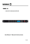
WPR - 1
User Manual
Reference Manual
Page 1
Read theseinstructions.
Keep theseinstructions.
Heed all warnings.
Follow all instructions.
Donot usethis apparatus near water.
Clean onlywith a damp cloth.
Do not block any of the ventilation openings. Install in accordance with the
manufacturer's instructions
Do not install near any heat sources such as radiators, heat registers, stoves, or
other apparatus thatproduceheat.
Donot install the safety purpose of hepolarized or grounding-type plug. A polarized
plug has two blades with one wide than the other. A grounding-type plug has two
blades and third grounding prong. The wide blade or the third prong is provided for
your safety. When the provided plug does not fit into your outlet, consult an
electrician for replacement oftheobsolete outlet.
Protect the power cord from being walked on or pinched, particularly at plugs,
convenience at plugs, convenience receptacles, and the point where they exit from
theapparatus.
Only use power cordfrom attachments/accessoriesspecified by themanufacturer.
Use only with a cart, stand, bracket, or table specified by themanufacturer, or sold
with the apparatus. When a cart is used, use caution when moving the
cart/apparatus combinationto avoidinjury from tip-over.
Unplug this apparatus during lightning storms or when unused for long Periods of
time.
Refer all servicing to qualified service personal. Servicing is required when the
apparatus has been damaged in any way, such as power-supply cord or plug is
damaged, liquid has been spilled or objects have fallen into the apparatus, the
apparatus has beenexposedto rain or moisture, doesnot operatenormally.
Page 2
Reference Manual
WPR 1
Multiband Sound Enhancer
Contents
Installation .............................................................................................................4
Connection .............................................. .............................................................4
Unbalanced Operating ..........................................................................................4
Balanced Operating ..............................................................................................4
Mains Connection .................................................................................................4
Control and connections ......................................................................................5
APPLICATIONS
Basic Applications ................................................................................................7
Typical Applications .............................................................................................7
Specifications ........................................................................................................9
Reference Manual
Page 3
WPR 1 Multiband Sound Enhancer
Installation
WPR 1 was carefully packed in the factory and the packagingwas designed toprotect the unit
from rough handling. Nevertheless, we recommend that you carefully examine the packaging
and its contents forany signs of physical damage, which may have occurred in transit.
If the unit is damaged, please do not return it to us. But notify your dealer and the shipping
company immediately. Otherwise claims for damage or replacement may not be granted.
Shipping claims must b e made by the consignee.
Rack mounting
The WPR 1 fits intoone standard rack unit of space (1.3/4). Please allow at least an additional
4depth for the connectors on the back panel. Be surethat there is enough air space around the
unit for cooling and please do not place the WPR 1 on high temperature devices such as
power amplifier etc. to avoid overheating.
Connectors
The audioinput and outputconnector are available inXLR connectors.
Due to frequently occurring problemswith compatibility. we would like to draw your attention to
the international standard IEC 268-12: for balanced operation. pin 1 should be connected to
ground, pin 2 should carry the positive signaland pin 3 the negative signal.
Important note: XLR connector/Pin1: ground, Pin 2: signal+, Pin 3: signal -.
Unbalanced Operating
Unbalanced operation is characterized by a single conductor shielded cable with the center
conductorcarryingthe signal and the shield at ground.
Balanced Operating
Balanced operation is defined as a two conductor shielded cable, where each of the two center
conductors carry the signal but of opposite phase. They have equal but inverted potential
differences from that o f ground.
Mains Connection
With the exception of the jack model, mains connection to the WPR 1 is established using a
removablepower cord, it also a n internal fuse holder,which meets all of the international safety
certification requirements.
Please make sure that all unit have a proper ground connection. For your own safety, it is
advisablenot to remove thegroundconnection or fail tomakethe connection tothe unit.Check
thattheunitisconfiguredtomatchyourACmain voltage requirement.
Important note: only replace the fuse with the correct value andtype!
Page 4
Reference Manual
WPR 1
Multiband Sound Enhancer
WPR 1 Front & Rear Panel Controls & Connections
[12]
Front Panel
[3]
[4]
[5]
[11]
[6]
[7]
[1] [2]
[1] [2]
[8]
[9]
[10]
[1] IN/OUT switch
This switch put both channels into operation.Withtheswitch in the OUT position, the unit
is bypassed.
[2] IN/OUT LED
This LED indicates both the status of thechannels, if the channelsare bypassed, the LED
is red; ifthechannelsare activated. the LED lights up green.
[3] SHIFT switch
This switch determines the cut-off frequency of the bass processor. Depending on the
programme material, you can select a cut-off frequency of 50 or 100Hz.
[4] LOWMIX control
The LOW MIX control determines the amount of signal used for sound enhancement
(from zero to maximum).Thesetting depends onthe application you are addressing.
please note: that the bass processor should be set carefully to avoid possible speaker
damage.
[5] TUNE control
The TUNE control sets the lower cut-off frequency of the high-pass filter. Using this
control you can select the frequencies that are routed to the especial processor. the cutoff frequency can be adjusted within a range of 1 to 8 kHz.
[6] PROCESS control
The PROCESS control determines the function of the device.When turning the control in
clockwise direction. The function is actioned, which increases the signals transparency
and sharpness.
Please note that with classical programme material, acoustic instruments or with output
signal that already include sufficient treble frequencies. The classic set should be
preferred. However when processing. for instance, a slapped bass guitar, it is the pop
settingwhichshould dominate.
[7] HIGHMIX control
The HIGH MIX control determines the amount of signal used for sound enhancement
(from zero to maximum).
Reference Manual
Page 5
WPR 1 Multiband Sound Enhancer
It depends on the application whether a high-quality system is to be given the finishing
touch with the WPR 1. or whether maximum intelligibility is to be achieved in a relatively
poor soundreinforcement system.
[8] PHASE INVERT switch
The PHASE INVERT switch set whether the mono low-frequency signal phase in the 0?
or 180?.
[9] X'OVER FREQUENCY control
The X'OVER FREQUENCY control sets the point of mono low-frequency signal. The
control can be adjusted within a range of 100to 250 Hz
[10] OUTPUT control
TheOUTPUT control sets themono low-frequency signal output level. The control can be
adjusted within a range of -? to +12dB.
[11] CLIP LED
The CLIP LED indicates the status of mono low-frequency signal output level clip. If
output level clip, the LED is red.
[12] LEVEL LED
TheLEVELLED indicates theoutputlevel of the dual channel. if output level clip, the LED
is red.
Rear Panel
[1] INPUT connection
Both balanced (3-pin female XLR type connectors) input connectors are available. A 600
ohm line should be used for both. Use the INPUT LEVEL control to set the rated input
level from -40 or -2dB.
[2] OUTPUT connection
Both balanced (3-pin female XLR type connectors) output connectors are available. A
600 ohm line should be used for the balanced XLRs. Use the OUTPUT LEVEL control to
set the rated nominal output level from -40 to-2 dB.
[3] MONO BASS OUTPUT connection
One balanced (3-pin female XLR type connector) output connector is available. A 600
ohm line should be used for the balanced XLRs. Use the OUTPUT LEVEL control to set
the ratednominalmono low-frequency signal outputlevel from -? to +12 dB.
Page 6
Reference Manual
WPR 1
Multiband Sound Enhancer
APPLICATIONS
Basic Applications
We recommend setting the processor as indicated in the following three sections. This will
give you a better idea of switch and control functionality.
Set the WPR 1 tobypass mode (the LED next to theIN/OUTswitch osred).
Set the TUNE controls to center position and the PROCESSOR controls fully counterclockwise.
Turn the MIX controls fully CCW and depress the IN/OUT switch. New turn the LOW MIX and
HIGH MIX controls of the bass and high-frequency sections slowly clockwise unit the
fundamental bass and high frequencies became more emphasized and the sonic image
begins toopen upor to widen.
The quality of the sound enhanced signal can be adapted to the programme material by
varying the cutoff frequency usingtheSHIFTswitches and/or the TUNE controls.
When using enhancers or exciters it is easy to get carried away. Therefore, we recommend
regular A/B comparisons(IN/OUT) while setting the controls, in order to constantly check the
signals integrity. Rule of thumb. the enhancers effect only should be noticeable when it is
lacking but not when it is present !
Typical applications
In this section wewill discuss a few typical applications of the WORKWPR 1.
Sound Enhancement During Replay
For this application, the WPR 1 follows the master or multi-track recorder, inserted between
tape machine and mixer (or amplifier). Of course, a cassette recorder, or similar, can also be
used assignal source.
If a companding noise reduction system is used in this situation. it should precede the WORK
WPR 1.
Enhancement The SoundOfEffects Devicesancem
Often, signal processing units such as flangers, phasers, distortion, chorus, delay and reverb
units etc. considerably limit the signals sound quality. Here too, the WPR 1 will be of help.
Simply insert the unit after the effects device, if there are several devices, insert the WPR 1 as
the last unit in thechain.
Enhancement The SoundOfP.A. Systems
If used inP.A. and other sound reinforcement systems for background or livemusic, the WPR 1
offers astoundingadvantages
In audio systems for announcements and background music, the WPR 1 is place in a similar
way to recording and tape duplication-directly before the power amp. The intelligibility and
range ofyour system will be improved and the sonic image will become clear and transparent,
even at low volume levels, problems caused by background.
Reference Manual
Page 7
WPR 1 Multiband Sound Enhancer
Noise fluctuations, room acoustics(reflections) andspeakersetup can be solvedmoreeasily.
For instance, in discos orclubs you do not need to constantly readjust the high frequencies as
the place becomes increasingly crowded: you will be able to protect your speaker system and
the hearing of visitors.
Backgroundmusic in bars and restaurantscan be heard easily. It does not annoy your guests
becauseits volume had tobe turned up toofar.
The sound of any P.A. system will be improved by the WPR 1. For example, the vocals and
speech of music groups or speech transmissions will be considerably more transparent and
intelligible, the instruments c an bedistinguished more easily.
The WORK WPR 1 will increase the speaker systems acoustic performance and its ability to
penetrate a room, particularly in places withdifficultacoustics.
The system also needs less effective amplifier power, since the subjectively heard volume
level increases. Powerful and detailed sound reproduction can also be achieved with weak
systems. It helpswhen you do not have to spend a small fortune on upgradingyour system.
Enhancement The Sound Of Sample Systems
CHANNEL1
MIXER
CHANNEL2
PARALLEL
FULL RANGE OUTPUT
STEREO
CHANNEL 1
+
BRIDGE
-
?
PARALLEL
BRIDGED
1.44V
DIRECTOUT
INPUT
0.7V
LIFT
PIN1:SIGNALGND
PIN2:SIGNAL+
PIN3:SIGNAL-
RISKOFELECTRICSHOCK
DONOTOPEN
WARNING - TOREDUCETHERISKOFFIRE
ORELECTRICALSHOCK,DONOTEXPOSETHIS
EQUIPMENTTORAINORMOISTURE.
SASERIES
NOUSERSERVICEABLEPARTSINSIDE
MODEL:
REFERSERVICINGTOQUALIFIEDSERVICEPERSONAL
GND
BRIDGEINPUT
CLASS2WIRINGPERMITTED
CLASS1WIRINGREQUIRED
INBRIDGEMONO
CONNECTION
OUTPUTASSIGNMENT
OUT1: PIN1+:SIGNALCH1
PIN1-:GROUNDCH1
PIN2+:SIGNALCH2
PIN2-:GROUNDCH2
OUT2: PIN1+:SIGNALCH2
PIN1-:GROUNDCH2
PIN2+
PIN2-
LOUDSPEAKERS
SPEAKEROUTPUT:
SERIALNO.:
1.0V
1
INPUT
CAUTION
?
STEREO
2
?
BRIDGE
OUT2
OUT1
AVIS:
RISQUEDECHOCELECTRIQUE-NEPASOUVRIR.
MODEL:
ACVOLTS:
AMPS:
RATEDOUTPUT:
BRIDGEMONOOUTPUT
OUT1: PIN1+:SIGNAL
PIN2+:GROUND
+
-
CHANNEL 2
PARALLEL
MONO BASS OUTPUT
STEREO
LOUDSPEAKERS
+
BRIDGED
-
?
PARALLEL
BRIDGE
?
STEREO
BRIDGED
2
SASERIES
MODEL:
1.44V
DIRECTOUT
INPUT
1
INPUT
LIFT
PIN1:SIGNALGND
PIN2:SIGNAL+
PIN3:SIGNAL-
GND
BRIDGEINPUT
?
CAUTION
RISKOFELECTRICSHOCK
DONOTOPEN
WARNING -
SPEAKEROUTPUT:
CLASS2WIRINGPERMITTED
CLASS1WIRINGREQUIRED
INBRIDGEMONO
CONNECTION
OUTPUTASSIGNMENT
OUT1: PIN1+:SIGNALCH1
PIN1-:GROUNDCH1
PIN2+:SIGNALCH2
PIN2-:GROUNDCH2
OUT2: PIN1+:SIGNALCH2
PIN1-:GROUNDCH2
PIN2+
PIN2BRIDGEMONOOUTPUT
OUT1: PIN1+:SIGNAL
PIN2+:GROUND
OUT2
?
TOREDUCETHERISKOFFIRE
ORELECTRICALSHOCK,DONOTEXPOSETHIS
EQUIPMENTTORAINORMOISTURE.
NOUSERSERVICEABLEPARTSINSIDE
REFERSERVICINGTOQUALIFIEDSERVICEPERSONAL
?
SERIALNO.:
1.0V
0.7V
Page 8
?
OUT1
AVIS:
RISQUEDECHOCELECTRIQUE-NEPASOUVRIR.
MODEL:
ACVOLTS:
AMPS:
RATEDOUTPUT:
Reference Manual
WPR 1
Multiband Sound Enhancer
SPECIFICATIONS
INPUT
Type:
Input Impedance:
Nominal Operating Level:
Maximum Input Level:
CMRR:
RF filtered, servo-balanced input
40kohms. balanced
-40 dBV to -2dBu
+20 dBu unbalanced
better than 40 dB
OUTPUT
Type:
Output impedance:
Maximum Output Level:
Bandwidth:
THD @ +4dBu:
IM (SMPTE)@ +10dBu:
Noise & Hum, unity gain:
Crosstalk @ 20kHz:
DC-decoupled balanced output stage
40 ohms, balanced
+20 dBu unbalanced
10 Hz -50 kHz, +0, -1 dB
0.005% typ.(all controls set to minimum)
0.01% typ.
-94 dBu (all controls set to minimum)
better than -83 dBu
MONO BASS OUTPUT
Type:
Output impedance:
Maximum Output Level:
Bandwidth:
THD @ +4dBu:
IMD(SMPTE) @ +10dBu:
Noise & Hum, unity gain:
DC-decoupled balanced output stage
40 ohms, balanced
+20 dBu unbalanced
10 Hz -250 kHz, +0, -1 dB
0.005% typ.(all controls set to minimum)
0.01% typ.
-94 dBu (all controls set to minimum)
LOW BAND PROCESSOR
SHIFT switch:
LOW MIX control:
switch able from 50Hz to 100Hz
variable from OFF to MAX
HIGH BAND PROCESSOR
Type:
TURN control:
PROCESS control:
HIGH MIX control:
WORK Processor
variable from 1 to 8 kHz
variable from CLASSIC to POP
variable from OFF to MAX
MONO LOW-FREQUENCY
SIGNAL PROCESSOR
Type:
PHASE switch:
X'OVER FREQUENCY control:
OUTPUT control:
WORK Processor
switch able from0? to 180?
variable from 100 to 250 Hz
variable from -? to +12 dB
Reference Manual
Page 9
WPR 1 Multiband Sound Enhancer
INDICATORS
IN/OUT LED (two color)
LEVEL metter (dual channel four
step/three color)
CLIP LED (two color)
POWER REQUIREMENTS
Main Voltage:
Power Consumption:
Fuse:
100~120/200~240 VAC 50/60Hz
10 Watts
0.375 A. slow-blow
WEIGHT
Net Weight:
Shipping Weight:
3.2kg
3.8kg
Page 10
Reference Manual
Equipson, S.A.
www.equipson.es
[email protected]