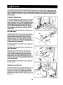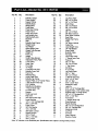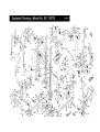
1
Patent Pending
Model No. 831.159730
Serial No.
USER'S MANUAL
The serial number is found in the
location shown below. Write the
serial number in the space above.
Serial
Number
Decal
EXERCISE
EQUIPMENT
H
__LP
LI
N
E_ !
1-800-72,6-6879
SEARS, ROEBUCK AND CO.
HOFFMAN ESTATES, IL 60179
CAUTION
Read all precautions and instructions in this manual before using
this equipment. Save this manual for future reference.
www.weiderfitness.com
new products,
prizes,
fitness tips, and much morel
2
3
.4
23
25
26
27
Back Cover
Back Cover
Important
Precauttons
Before You Begm
Assembly
Cable Diagrams
Adjustment
Trouble-shooting
and Mamtenance
Weight Resistance Chart
Ordering Replacement Parts
Full 9g-day Warranty
Note. A PART LIST/EXPLODED
DRAWING and a PART IDENTIFICATION
CHART are attached in the center of
th_s manual Remove the PART LIST/EXPLODED
DRAWING and the PART IDENTIFICATION
CHART before
beginning
assembly.
WARNING:
^*1
To reduce the risk of serious injury, read the following Important precautions before using the home gym.
1. It is the responsibility of the owner to ensure
that all users of the home gym are adequately informed of all precautions.
7. Always stand on a foot plate when performing an exercise that could cause the home
gym to tip.
2. Read all instructions in this manual and in
the accompanying literature before using the
home gym.
8. Keep hands and feet away from moving parts.
9. Keep children under the age of t2 and pets
away from the home gym at all times.
3. If you feel pain or dizziness at any time while
exercising, stop immediately and begin cooling down.
t0. Always wear athletic shoes for foot protection when exercising.
4. Use the home gym only on a level surface.
Cover the floor or carpet beneath the home
gym for protection.
11. Never release the press arms, butterfly arms,
leg lever, lat bar or ab strap while weights are
raised. The weights will fall with great force.
5. Inspect and tighten all parts often. Replace
any worn parts immediately.
12. Alwavs disconnect the lat bar or ab strap
frgm the home avm when Derformina
an
exercise that does not use the attachments.
6. Make sure the cables remain on the pulleys
at all times. If the cables bind while you are
exercising, stop immediately and make sure
the cables are on all of the pulleys.
13. The home gym Is intended for home use only.
Do not use the home gym in a commercial,
rental or institutional setting.
WARNING: Before beginning this or any exercise program, consult your physician. This is especially
important for persons over the age of 35 or persons with pre-existing health problems. Read all
instructions
before using. SEARS assumes no responsibility
for personal injury or property damage
sustained by or through the use of this product.
2
Thank you for selecting the innovative and versatile
WELDER®PRO 9940 Home Gym. The WELDER®PRO
9940 offers a unique selection of weight stations
designed to develop every major muscle group of the
body. Whether your goal is to tone your body, build
dramatic muscle size and strength or improve your
cardiovascularsystem, the WELDER®PRO 9940
makes it easy to achieve the resultsyou want.
HELPLINE at 1-800-736-6879, Monday through
Saturday, 7 a.m. until 7 p.m. Central Time (excluding
holidays). To help us assist you, please note the product model number and serial number before calling.
The model number is 831.159730. The serial number
can be found on a decal attached to the WELDER®
PRO 9940 Home Gym (see the front cover of this
manual).
For your benefit, read this manual carefully before
using the WELDER®PRO 9940 Home Gym. If you
have additionalquestions, please call our toll-free
Please usa the drawing below to familiarize yourself with the major parts and how they fit together.
ASSEMBLED
DIMENSIONS:
Height: 77 in.
Width: 80 in.
Depth: 55 in.
Lat Bar
High Pulley
Station
BuRe_y
Arms
Ab Pulley
Station
Backrest
[
Press Arms
Curl Pad
Leg Press
Plate
Foam Pads
Seat
Leg
Lever
Low Pulle_
Station
Weight
Stacks
Foot Plate
3
Leg Press
Lever
Note: This introduction will save you more time
than it takes to read itl
MaDdr_
_lngs _Ser for_yo.rs=_i
by anyone. However,;iHs_i_to_ealize'
tl_t your newequi._..:is
wmtake_
_
a,_
Identifying Parts
To help you identifythe small parts used in assembly,we have included a PART IDENTIFICATION
CHART located in the center of th_smanual. Place
the chart on the floor or work table and use it to
quickly identify different parts as you open the packages for each step. Note Some small parts may
,
prod- _ have been pra-attached for shipping. If a part is not
in the parts bag, check to see if it has been preattached.
houm.!Mo=
peo-
Orienting Parts
As you assemble this product, be sure that all parts
are oriented as shown in the drawings.
by.deddlrig
tomakethe.ta_ eejWal_i,usam--
bWy
_1iOo:=_==li_s:Y=;J
iiiis wantio'ix_nplete.
the precessover_tooupieof eventhg_
,
'_.
Some assembly steps require two people.
Tightening Parts
Tighten all parts as you assemble them, unless
instructedto do otherwise.
Giving Yourself a Good Start
Before you begin the assembly process itself, take
the bme to complete the steps outlined here.
Lining Up the Tools
Assembly requires the following tools (not included):
• Two (2) adjustable wrenches
Clearing the Workspace
Clear a workspace that is large enough to hold all
parts and allow you to walk all the way around the
assembled equipment.
• One (1) standard screwdriver
• One (1) phillipsscrewdriver
Unpacking the Box
To make the assembly process as smooth as possible, we have broken it into separate stages. All parts
used in each stage are found in individualpackages
in the shippingbox. Place all parts in a cleared area
and remove the packing materials. Do not dispose of
the packing materials until assembly _scompleted.
• One (1) rubber mallet
• Lubricant,such as grease or petroleumjelly,
and soapy water
• Tape, such as clear tape or maskingtape
Assembly will be more convenient if you have a
socket set, a set of open-end or closed-endwrenches
or a set of ratchet wrenches.
Important: Wait until you begin each assembly
stage to open the parts bag labeled for that
assembly stage,
The Four Stages of the Assembly
Process
Frame Assembly
You will begin by assembhng the base and the
upright frames that serve as the skeleton of the
equipment.
Cable Assembly
This assembly COmpletesthe cables and pulleys
that connect the moving arms with each other and
with the weights.
Arm Assembly
This assembly completes the press and butterfly
arms that you operate while you are exercising.
Seat Assembly
This assembly completes the seat and backrest
that supped your body while you are exercising.
4
la
28
1.
Before beginning, make sure that you have read
and understood the information on page 4.
4
Locate and open the parts bag labeled "FRAME
ASSEMBLY."
92
See drawing la. Press a 2" Square Inner Cap (28)
into each end of the Butterfly Base (4). Press two 2"
Square Inner Caps (28) into the Weight Base (5).
Insert four 5/16" x 2 1/2" Carriage Bolts (92) up
through the indicated holes in the Butterfly Base (4).
Insert a 3/8" x 3 1/2" Carriage Bolt (95) up through
the hole at the end of the ButterflyBase. Note: If the
Bolts fall out, secure them by putting a small
piece of tape over the head of each Bolt. Place the
Butterfly Base fiat on the floor.
28
lb
89
See drawing lb. Attach the Weight Base (5) to the
Butterfly Base (4) with two 5/16" x 2 3/4" Bolts (89), a
Support Plate with 3 1/2" center holes (93), and two
5/16" Nylon Locknuts (64). Do not tighten the Nylon
Locknuts yet.
64
Note: There are three kinds of Support Plates. The
main difference between them is the distance
between the holes. When you need a Support
Plate, find the type with holes that will fit over the
Bolts you are using.
2,
5
2a
See drawing 2a. Press a 2" Square Inner Cap (28)
into the end of the Press Base (6).
28
Attach a 3 1/2" Pulley (24) to each of the brackets on
the Weight Base (5) with a 3/8" x 1 3/4" Bolt (57) and
a 318"Nylon Jamnut (63).
102
Insert four 5/16" x 2 1/2" Carriage Bolts (92) up
through the indicated holes in the Press Base (6).
Insert a 3/8" x 2 1/2" Carriage Bolt (101) and a 318 x
4" Carriage Bolt (102) up through the indicated holes
at the end of the Press Base (6).
See drawing 2b. Attach the Press Base (6) to the
Weight Base (5) with two 5/16" x 2 3/4" Bolts (89), a
Support Plate with 3 1/2" center holes (93), and two
5/16" Nylon Locknuts (64). Do not tighten the Nylon
Locknuts yet.
92
101
2b
64
93
89
5
3.
Place the bracket on the lower end
Upright (1) over the indicated 5/16"
Bolts (92) in the Butterfly Base (4).
5/16" Nylon Locknuts (64) onto the
tighten the Nylon Locknuts yet.
of the Butterfly
x 2 1/2" Carriage
Hand tighten two
Bolts. Do not
1
64
4\
92
4,
Press three 2" Square Inner Caps (28) into the
ButterflyTop Frame (33). Press two 1"Round Inner
Cap (86) into the top of the ButterflyTop Frame (33).
4
8c
86
3 _28
Attach the Butterfly Top Frame (33) to the indicated
bracket at the top of the ButterflyUpright (1) with two
5/16" x 2 3/4" Bolts (89), a Support Plate with 3 1/2"
center holes (93), and two 5/16" Nylon Locknuts(64).
84 u
5. Attach the Butterfly Seat Frame (14) to the Front Leg
(20) with two 5/16" x 2 3/4" Bolts (89), two 5/16"
Washers (36), and two 5/16" Nylon Locknuts (64). Do
not tighten the Nylon Locknuts yet.
Slide the bracket on the Front Leg (20) onto the two
5/16" x 2 1/2" Carriage Bolts (92) in the ButterflyBase
(4). Hand tighten two 5/16" Nylon Locknuts (64) onto
the Bolts. Do not tighten the Nylon Locknute yet,
Attach the ButterflySeat Frame (14) to the Butterfly
Upright (1) with two 5/16" x 2 3/4" Bolts (89), two
5/16" Washers (36) and two 5/16" Nylon Locknuts
(64). Do not tighten the Nylon Locknuts yet.
6
89
6.
Press a 2" Square Inner Cap (28) half way into the
top of the Front Leg (20), Press a 2" Square Inner
Cap (28) into each end of the Small Leg Lever (41).
Attach the Bumper (40) to the indicated hole in the
Front Leg (20) with a 1"Tap Screw (80).
40
Lubricate the 3/8" x 3 1/4" Bolt (62). Attach the Small
Leg Lever (41) to the bracket on the Front Leg (20)
with the Bolt and a 3/8" Nylon Jamnut (63). Do not
overtighten the Nylon Jamnut; it must be easy to
pivot the Leg Lever.
7.
Lubricate
Press a 1" Square Inner Cap (98) into the small tube
on the Press Upright (2).
64
Place the bracket on the lower end of the Press
Upright (2) over the indicated 5/16" x 2 1/2" Carriage
Bolts (92) in the Press Base (6). Hand tighten two
5/16" Nylon Locknuts(64) onto the Bolts. Do not
tighten the Nylon Locknuts yet.
Place the bracket on the lower end of the Support
Frame (3) over the indicated 3/8" x 2 1/2" Carriage
Bolt (101) and the 3/8" x 4" Carriage Bolt (102) in the
Press Base (6). Hand tighten a 3/8" Nylon Jamnut
(63) onto the 3/8" x 2 1/2" Carriage Bolt (101). Do not
tighten the Nylon Jarnnut yet.
Note: Do not thread a Jamnut onto the 3/8" x 4"
Carriage Bolt (102) yet.
63
Attach the Support Frame (3) to the Press Upright (2)
with two 5/16" x 2 1/2" Carriage Bolts(92) and two
5/16" Nylon Locknuts (64). Do not tighten the Nylon
Locknuts yet.
/
/
102
101
92
8.
Press a 2" Square Inner Cap (28) into the Press Top
Frame (9).
Attach the Press Top Frame (9) to the indicated
bracket at the top of the Press Upright (2) with two
5/16" x 2 3/4" Bolts(89), a Support Plate with 3 1/2"
center holes (93), and two 5/16" Nylon Locknuts (64).
_>
7
._28
9.
Press a 2" Square Inner Cap (28) into the Press Seat
Frame (7).
Slide the bracket on the Press Seat Frame (7) onto
the indicated 5/16" x 2 1/2" Carriage Bolts (92) in the
Press Base (6). Hand tighten two 5/16" Nylon
Locknuts (64) onto the Bolts. Do not tighten the
Nylon Locknuts yet.
Attach the Press Seat Frame (7) to the Press Upright
(2) with two 5/16" x 2 3/4" Bolts(89), two 5/16"
Washers (36), and two 5/16" Nylon Locknuts (64). Do
not tighten the Nylon Locknuts yet.
10. Lubricatethe 3/8" x 3" Bolt (88). Attach the Leg Press
Lever (83) to the Press Base (6) with the Boltand a
3/8" Nylon Locknut (50). Do not overtighten the
Nylon Locknut; the Leg Press Lever must pivot
easily.
11. Place two Weight Bumpers (51) over the indicated
holes in the Weight Base (5). Slide a Weight Guide
(15) into each of the holes.
Attach the indicatedWeight Guide (15) to the Weight
Base (5) with a 3/8" x 2 3/4" Bolt (46), two 3/8" Flat
Washers (48), and a 3/8" Nylon Locknut (50).
Slide six Weights (21) onto the Weight Guides (15).
Make sure the Weights are turned so the pin
grooves point towards the floor.
Press a Weight Tube Bumper (18) intothe lower end
of the Short Weight Tube (17). Slide the Weight Tube
into the center holes in the Weights (21).
Slide a Top Weight (16) onto the Weight Guides (15).
Note: Make sure the Top Weight is turned so the
groove fits over the welded pin on the Weight
Tube (17).
8
36
12. Place two Weight Bumpers (51) over the indicated
holes in the Weight Base (5). Slide a Weight Guide
(15) into each of the holes.
12
Attach the indicated Weight Guide (15) to the Weight
Base (5) with a 3/8" x 2 3/4" Bolt (46), two 3/8" Flat
Washers (48), and a 3/8" Nylon Locknut (50).
Slide ten Weights (21) onto the Weight Guides (15).
Make sure the Weights are turned so the pin
grooves point towards the floor.
Press a Weight Tube Bumper (18) into the lower end
of the Long Weight Tube (70). Slide the Weight Tube
into the center holes in the Weights (21).
Pin
Slide a Top Weight (16) onto the Weight Guides (15).
Note: Make sure the Top Weight is tumed so the
groove fits over the welded pin on the Weight
Tube (70).
51
5
13. Place the Weight Top Frame (66) on the indicated
brackets on the Uprights (1 and 2). Note: The four
Weight Guides (15) must be behind the Weight
Top Frame, as shown in step 14.
13
Attach the Weight Top Frame (66) to the ButterflyTop
Frame (33) with two 3/8" x 2 3/4" Bolts(46), a
Support Plate with 4" center holes (94), and two 3/8"
Nylon Locknuts (50). Do not tighten the Nylon
Locknuts yet.
Attach the Weight Top Frame (66) to the bracket on
the ButterflyUpright (1) with two 3/8" x 2 3/4" Bolts
(46), a Support Plate with 2 1/2" center holes (34),
and two 3/8" Nylon Locknuts (50). Do not tighten the
Nylon Locknuts yet.
14. Attach the Weight Top Frame (66) to the Press Top
Frame (9) with one 3/8" x 2 3/4" Bolt (46), a Support
Plate with 4" center holes (94), and a 3!8" Nylon
Locknut (50). Slide a 3 1/2" Pulley (24) with a Cable
Trap (25) onto a 3/8" x 4" Bolt (78). Insert the Bolt
through the Support Plate (94) and hand tighten a
3/8" Nylon Locknut (50) onto it.
Attach the Weight Top Frame (66) to the bracket on
the Press Upright (2) with two 3/8" x 2 3/4" Bolts (46),
a Support Plate with 2 1/2" center holes (34) and two
3/8" Nylon Locknuts (50). Do not tighten the Nylon
Locknuts yet.
9
46
34_46
,. _¢U-o'_'=_._ 50
15. Attach each of the four Weight Guides (15) to the
Weight Top Frame (66) with a 3/8" x 3 3/4" Bolt (59),
a 3/8" Flat Washer (48), and a 3/8" Nylon Locknut
(50).
15
48
50
Important: Go back and fully tighten all Nylon
Locknuts used in steps 1 through 15.
16. Locate and open the parts bag labeled "ARM
ASSEMBLY."
Press a Plastic Bushing (100) onto each welded tube
on the Press Frame (8).
Lubricate the 3/8" x 8" Bolt (52). Attach the Press
Frame (8) to the welded tubes on the Press Base (6)
with the Bolt and a 3/8" Nylon Locknut (50). Do not
overtighten the Nylon Locknut; it must be easy to
pivot the Press Frame,
Lubricate
52
17. Press a 1 3/4" Square Inner Cap (35) into the top of a
Press Arm (77). Press a 1" Round Inner Cap (76) into
the indicated hole in the Press Arm.
Attach the Press Arm (77) to the bracket on the Press
Frame (8) with two 5/16" x 2 112"Bolts(87) and two
5/16" Nylon Locknuts (64).
Repeat this step to assemble the second Press Arm
(77, not shown).
35
64
77
10
18. Press a 1 3/4" Square Inner Cap (35) into each end
of the Right Butterfly Arm (11). Wet the lower end of
the Arm with soapy water. Slide a Butterfly Foam Pad
(29) onto the lower end of the Arm.
18
33
Axle
11
\
Lubricatethe indicated axle on the ButterflyTop
Frame (33). Orient the Right ButterflyArm (11) as
shown and slide it onto the axle. Secure the Butterfly
Arm with two Retainer Rings (31) and a 1" Round
Outer Cap (38). Note: Place the Retainer Rings on
top of the inverted Outer Cap and gently tap the
Cap onto the axle with a hammer. Make sure the
teeth on the Retainer Rings bend towards the Cap
as shown in the inset drawing.
Repeat this step to assemble the Left ButterflyArm
(10, not shown).
19. Locate and open the parts bag labeled "CABLE
ASSEMBLY." For Cable identification
and routing
during steps 19 to 49, refer to the Cable Diagrams
and Cable ID Chart on pages 23 and 24.
19
84
Bracket
Identify the Butterfly Cable (73). It is approximately
52" long and it has a closed loop on each end. Attach
the ButterflyCable to the bracket on the Left Butterfly
Arm (10) with a 3/8" x 1" Bolt (84) and two 3/8" Nylon
Jamnuts (63). Note: The loop on the Cable and the
two Nylon Jamnuta must be mounted underneath
the welded bracket.
lOj
// 7320. Locate and open the parts bag labeled "PULLEY
BAG 2." Remove one "V"-Pulley (27) from the
bag. Leave the remaining pulleys in the bag for
identification of the Pro Pulley,
2O
27
=J
Wrap the ButterflyCable (73) around a "V'-Pulley
(27) in the direction shown.Attach the "V"-Pulley and
a Large Cable Trap (32) to the bracket on the back
of the Butterfly Upright (1) with a 3/8" x 2 1/2" Bolt
(53) and a 3/8" Nylon Locknut (50). Make sure the
Large Cable Trap is oriented as shown.
' Bracket
"'_ 1
11
53
21. Remove both 3 112"Pulleys (24) from the pre-assembled Small Pulley Bracket (22).
1
2.
Wrap the Butterfly Cable (73) around a 3 1/2" Pulley
(24) in the direction shown. Attach the Pulley to the
Small Pulley Bracket (22) with a 3/8" x 1 3/4" Bolt
(57) and a 3/8" Nylon Locknut (50). Make sure the
Small Pulley Bracket is oriented exactly as
shown.
22. Wrap the Butterfly Cable (73) around a =V"-Pulley
(27) in the directionshown. Attach the =V-Pulley and
a Large Cable Trap (32) to the bracket on the back
of the Butterfly Upright (1) with a 3/8" x 2 1/2" Bolt
(53) and a 3/8" Nylon Locknut (50). Make aura the
Large Cable Trap is oriented as shown.
22
Bracket
l
73
23. Attach the ButterflyCable (73) to the bracket on the
Right ButterflyArm (11) with a 3/8" x 1" Bolt (84) and
two 3/8" Nylon Jamnuts (63). Note: The loop on the
Cable and the two Nylon Jamnuta must be mounted undemeath the welded bracket.
_
23
84
Bracket
24. Identify the Ab Cable (74). It is approximately 224"
long, and it has a ball on one end and a threaded
shaft on the other. You will start by attaching the end
of the Cable with the ball.
Wrap the Ab Cable (74) around a 3 1/2" Pulley (24) in
the direction shown. Place two Pulley Covers (47)
over the Pulley, so that the slots in the Pulley Covers
are placed over the Cable. Attach the Pulley and
Pulley Covers to the indicatedhole in the Butterfly
Upright (1) with a 3/8" x 3 3/4" Bolt (59), two 3/8" Flat
Washers (48), and a 3/8" Nylon Jamnut (63). Make
sure the Cable is between the Pulley and the
welded pin on the Upright.
12
47
_"63
25. Remove both 3 1/2" Pulleys (24) from the pre-assembled Adjustable Pulley Plates (23).
25
J
J
Wrap the Ab Cable (74) around a 3 1/2" Pulley (24) in
the direction shown. Attach the Pulley and a Cable
Trap (25) to the top hole in the two Adjustable Pulley
Plates (23) with a 3/8" x 2" Bolt (54) and a 3/8" Nylon
Locknut (50). Make sure the Cable Trap and the
Pulley Plates are oriented as shown.
25
23
74
26. Wrap the Ab Cable (74) around a 3 1/2" Pulley (24) in
the direction shown, Attach the Pulley to the Small
Pulley Bracket (22) with a 3/8" x 1 3/4" Bolt (57) and
a 3/8" Nylon Locknut (50). Make sure the Pulley
Bracket is oriented as shown.
A
26
57
27. Wrap the Ab Cable (74) around a 3 1/2" Pulley (24) in
the direction shown. Attach the Pulley and a Cable
Trap (25) to the welded bracket on the Butterfly Base
(4) with a 3/8" x 2" Bolt (54) and a 3/8" Nylon Locknut
(50). Make sure the Cable Trap is oriented as
shown.
t3
28. Wrap the Ab Cable (74) around a 3 1/2" Pulley (24) in
the direction shown. Slide the Pulley and a Cable
Trap (25) onto the 3/8" x 3 1/2" Carriage Bolt (95)
already inserted into the Butterfly Base (4). Secure
the Pulley with a 3/8" Nylon Jamnut (63). Make sure
the Cable Trap is oriented as shown.
28
63
I
24
74
I
Route the threaded end of the Ab Cable (74) under
the 3 1/2" Pulley (24) that is already mounted on the
Weight Base (5). Make sure the Cable is routed in
the direction shown.
Note: For clarity, this and the following drawings
show some parts removed.
29. Wrap the h,b Cable (74) around a 4 1/2" Pulley (82) in
the direction shown. Attach the Pulley inside the indicated bracket on the Weight Top Frame (66) with a
3/8" x 1 3/4" Bolt (57) and a 3/8" Nylon Locknut (50).
Make sure the threaded end of the Ab Cable is
routed through the bracket, as shown.
29
82
50
/66
./
./
30. Attach the threaded end of the Ab Cable (74) to a =U'Bracket (97) with a 1/4" Flat Washer (71) and a 1/4"
Nylon Locknut (68).
Attach the "U"-Bracket (97) to the hole in the Short
Weight Tube (17) with a 5/16" x 1 3/4" Bolt (96) and a
5/16" Nylon Locknut (64). Note: Do not completely
tighten the Nylon Locknut; it should be threaded
only two turns onto the end of the Cable, as
shown in the inset drawing.
14
3O
68
31. Remove a Pro Pulley (26) from the bag labeled
"PULLEY BAG 2".
31
Identifythe Low Pulley Cable (75). It is approximately
143 1/2" long and it has a ball on one end and a loop
on the other. Route the end with the loop through the
slot in the cable guide on the Butterfly Base (4).
Route the Low Pulley Cable (75) under a Pro Pulley
(26) as shown. Attach the Pro Pulley and a Cable
Trap (25) to the bracket on the Butterfly Base (4) with
a 3/8" x 2" Bolt (54) and a 3/8" Nylon Locknut (50).
Make sure the Cable Trap is oriented as shown•
32. Wrap the Low Pulley Cable (75) around a 3 1/2"
Pulley (24) in the direction shown. Attach the Pulley
and a Cable Trap (25) to the indicated hole in the
Butterfly Upright (1) with a 3/8" x 4 3/4" Bolt (60) and
a 3/8" Nylon Jamnut (63). Note: Thread the Jamnut
only two turns onto the Bolt, since you will later
attach another Pulley to the Bolt. Make sure the
Cable Trap is oriented as shown.
25
Guide
75
32
63
33. Wrap the Low Pulley Cable (75) over a 3 1/2" Pulley
(24) in the direction shown. Attach the Pulley and a
Cable Trap (25) to the lower hole in the Adjustable
Pulley Plates (23) with a 3/8" x 2" Bolt (54) and a 3/8"
Nylon Locknut (50). Make sure the Cable Trap is
oriented as shown.
33
34. Remove the 3/8" Nylon Jamnut (63) from the
3/8" x 4 3/4" Bolt (60) inserted into the Butterfly
Upright (1) in step 32.
34
Wrap the Low Pulley Cable (75) around a 3 1/2"
Pulley (24) in the direction shown. Attach the Pulley
and a Cable Trap (25) to the 3/8" x 4 3/4" Bolt (60)
with the 3/8" Nylon Jamnut (63). Make sure the
Cable Trap is oriented as shown.
15
54
\
35. Attach the loop on the end of the Low Pulley Cable
(75) to the indicated hole in the Small Leg Lever (41)
with a 3/8" x 2 3/4" Bolt (46), two 3/8" Flat Washers
(48), and a 3/8" Nylon Jamnut (63).
35
41
48
36. Remove a Pro Pulley (26) from the bag labeled
"PULLEY BAG 2".
Identifythe Press Cable (72). It is approximately 389
1/2" long and it has a ball on one end and a threaded
shaft on the other. You will begin by attaching the end
with the ball.
26
Wrap the Press Cable (72) around a Pro Pulley (26)
in the direction shown. Attach the Pulley to the indicated hole in the Press Top Frame (9) with a 3/8" x
3 1/2" Bolt (56), a 3/8" Flat Washer (48), and a 3/8"
Nylon Jamnut (63). Make sure the Cable is between
the Pulley and the welded pin on the Press Top
37. Route the threaded end of the Press Cable (72)
around the 3 1/2" Pulley (24) that is already mounted
on the Top Frame (9).
38. Wrap the Press Cable (72) around a 3 1/2" Pulley (24)
in the direction shown. Attach the Pulley to the indicated hole in the Press Upright (2) with a 3/8" x 3 3/4"
Bolt (59), a 3/8" Flat Washer (48) and a 3/8" Nylon
Locknut (50). Make sure the Cable Trap is oriented
as shown.
59
16
39. Important: Although the following steps are not
difficult to perform, the correct routing of the
cable is critical to the functioning of the home
gym. Please make sure that you wrap the cable
around the pulleys exactly as shown in each step.
39 /
Route the Press Cable (72) through the opening in
the Press Frame (8), and wrap the Cable around a
3 1/2" Pulley (24) in the directionshown. Route the
end of the Cable back through the opening in the
Press Frame.
Attach the Pulley (24) to the indicated hole in the
Press Frame (8) with a 3/8" x 3 1/4" Bolt (62), a 3/8"
Flat Washer (48) and a 3/8" Nylon Locknut (50).
Make sure the Pulley is mounted on the inside of
the Press Frame. Make sure the Cable Trap is oriented as shown.
40. Wrap the Press Cable (72) around a =V"-Pulley (27) in
the direction shown. Attach the =V'-Pulley and a Large
Cable Trap (32) to the small tube on the Press
Upright (2) with a 3/8" x 3 1/4" Bolt (62), a 3/8" Flat
Washer (48) and a 3/8" Nylon Locknut (50). Note:
The small tube has four adjustment holes. Mount
the "V"-Pulley in the hole farthest from the
Upright. Make sure the Cable Trap is oriented as
shown.
25
40
Small tube,
"last hole
72
62
41. Route the Press Cable (72) back through the opening
in the Press Frame (8) and wrap the Press Cable
around a 3 1/2" Pulley (24) in the directionshown.
Then, route the Press Cable back through the opening in the Press Frame (8).
Attach the Pulley (24) to the indicated hole in the
Press Frame (8) with a 3/8" x 3 1/4" Bolt (62), a 3/8"
Flat Washer (48), and a 3/8" Nylon Locknut (50).
Make sure the Pulley is mounted on the inside of
the Press Frame. Make sure the Cable Trap is oriented as shown.
42. Wrap the Press Cable (72) around a 3 112"Pulley
(24) in the direction shown. Attach the Pulley and a
Cable Trap (25) to the indicated hole on the far side
of the Press Upright (2) with a 3/8" x 4 3/4" Bolt (60)
and a 3/8" Nylon Jamnut (63). Note: Thread the
Jamnut only two turns onto the Bolt; you will later
attach another Pulley to the Bolt. Make sure the
Cable Trap is oriented as shown.
Route the Press Cable (72) back through the opening
in the Press Frame (8), so the end is in front of the
Press Frame.
17
fj
J
J
J
IL
f/t
f.,I
f..I
f_,d
F
A
.
43. Wrap the Press Cable (72) around a 3 1/2" Pulley
(24) in the direction shown. Attach the Pulley and a
Cable Trap (25) to the indicated hole on the far side
of the Leg Press Lever (83) with a 3/8" x 4 3/4" Bolt
(60) and a 3/8" Nylon Jamnut (63). Note: Thread the
Jamnut only two tums onto the Bolt; you will later
attach another Pulley to the Bolt. Make sure the
Cable Trap is oriented as shown.
2
25
44. Wrap the Press Cable (72) around a "V-Pulley (27)
in the direction shown. Attach the "V-Pulley and a
Large Cable Trap (32) underneath the Press Seat
Frame (7) with a 3/8" x 4 1/4" Bolt (85), a 3/8" Flat
Washer (48), and a 3/8" Nylon Locknut (50). Note:
the Press Seat Frame has five adjustment holes.
Mount the "V"-Pulley in the hole closest to the
Leg Press Lever. Make sure the Cable Trap is oriented as shown.
72
45. Wrap the Press Cable (72) around a 3 1/2" Pulley
(24) in the direction shown. Attach the Pulley and a
Cable Trap (25) to the near side of the Leg Press
Lever (83). Use the 3/8" x 4 3/4" Bolt (60) that was
inserted in step 43 and secure the Pulley with the
3/8" Nylon Jamnut (63). Make sure the Cable Trap
is oriented as shown.
45
83-,_
60_
25/
63
46. Wrap the Press Cable (72) around a 3 1/2" Pulley
(24) in the direction shown. Attach the Pulley and a
Cable Trap (25) to near side of the Press Upright (2).
Use the 3/8" x 4 3/4" Bolt (60) that was inserted in
step 42 and secure the Pulley with the 3/8" Nylon
Jamnut (63). Make sure the Cable Trap is oriented
as shown.
Wrap the Press Cable (72) around a 3 1/2" Pulley
(24) in the direction shown. Attach the Pulley and a
Cable Trap (25) to the 3/8" x 4" Carriage Bolt (102)
that was inserted into the Press Base (6) earlier.
Secure the Pulley with the 3/8" Nylon Locknut(50).
Make sure the Cable Trap is oriented as shown.
18
46 "
72
'
50
242
47. Route the threaded end of the Press Cable (72)
around the 3 1/2" Pulley (24) that was mounted on the
bracket on the Weight Base (5) in an earlier step.
47
48. Wrap the Press Cable (72) over a 4 1/2" Pulley (82)
in the direction shown. Attach the Pulley inside the
indicated bracket on the Weight Top Frame (66) with
a 3/8" x 1 3/4" Bolt (57) and a 3/8" Nylon Locknut
(50). Make sure the end of the Cable is routed
through the bracket, as shown.
48
50
82
49. Attach the threaded end of the Press Cable (72) to
the remaining =U"-Bracket (97) with a 1/4" Flat
Washer (71) and a 114"Nylon Locknut (68).
Attach the =U"-Bracket (97) to the hole in the Long
Weight Tube (70) with a 5/16" x 1 3/4" Bolt (96) and a
5/16" Nylon Locknut (64). Note: Do not completely
tighten the Nylon Locknut; it should be threaded
only two turns onto the end of the Cable, as
shown in the inset drawing.
Important: Follow all four cables from end to end
and make sure that they rest in the grooves of all
pulleys and that the cables and the pulleys move
smoothly.
19
68
72
50
50. Locate and open the parts bag labeled "SEAT
ASSEMBLY."
Attach the Backrest (12) to the indicated holes in the
Butterfly Upright (1) with two 1/4" x 2 1/2" Bolts (79)
and two 114"Flat Washers (71).
51. Insert a 1/4" x 2 1/2" Carriage Bolt (45) through the
center hole in a Seat Plate (65). Attach the Seat Plate
to the Press Backrest (99) with two 1/4" x 3/4" Bolts
(49).
Insert the 1/4" x 2 1/2" Carriage Bolt (45) into the
indicated hole in the Butterfly Upright (2) and secure
it with a 1/4" Flat Washer (71) and a 1/4" Nylon
Locknut (68). Secure the other end of the Press
Backrest (99) with a 1/4" x 2 1/2" Bolt (79) and a 1/4"
Flat Washer (71).
71
49
2O
52. Insert a 1/4" x 2 112"Carriage Bolt (45) through the
center hole in a Seat Plate (65). Attach the Seat Plate
to a Seat (13) with two 1/4" x 3/4" Bolts (49),
52
Insert the 1/4" x 2 1/2" Carriage Bolt (45) into the indicated hole in the ButterflySeat Frame (14) end
secure it with a 1/4" Flat Washer (71) and a 1/4"
Nylon Locknut (68). Secure the other end of the Seat
(13) with a 1/4" x 2 1/2" Bolt (79) and a 1/4" Flat
Washer (71).
Attach the other Seat (13) to the Press Seat Frame
(7, not shown) in the same manner.
53
43
30
Tube
53. Press 3/4" Round Inner Caps (43) into the ends of the
Pad Tube (42) and the indicatedtube on the Front
Leg (20),
Insert the Pad Tube (42) intothe indicated hole in the
Small Leg Lever (41). Slide Foam Pads (30) onto the
ends of the Pad Tube and the tube on the Leg Lever.
54. Press a 1 3/4" Square Inner Cap (35) into the indicated end of the Adjustment Tube (90).
30
54
35
Attach the Adjustment Tube (90) to the bracket (not
visible in the drawing) on the back of the Leg Press
Plate (55) with a 5/16" x 2 1/2" Bolt (87), two 5/16"
Washers (36), and a 5/16" Nylon Locknut (64).
Attach the Leg Press Plate (55) to the Leg Press
Lever (83) by placing the AdjustmentTube (90) into
the bracket on top of the Leg Press Lever and securing it with the Lock Pin (91). Note: The lip on the
Leg Press Plate must be on the upper edge.
55. Attach the Curl Pad (105) to the Cud Post (104) with
two 1/4" x 3/4" Bolts (49),
21
55
55
56. Apply the WELDER PRO 9940 decal in the location shown. Important: The warning decals shown below
have been attached to the home gym in the locations shown. If a decal is missing or illegible, please
call our customer hotline at the number on the front cover of this manual to order a replacement
decal. Apply the new decal in the appropriate location.
56
may resultinserious
injury.
• Readuser'smanual
andfollow all warnings
andoperatinginstructionspriorto use.
• Do notallowchildren
onor around machine.
• Replacelabelif
damaged,illegible,or
removed.
57. Make sure that all parts have been properly tightened. The use of the remaining parts will be explained in
ADJUSTMENT, beginning on page 25 of this manual.
Before using the home gym, pull each cable a few times to make sure that the cables move smoothlyover
the pulleys. If one of the cables does not move smoothly,find and correct the problem. IMPORTANT: If the
cables are not properly installed, they may be damaged when heavy weight is used. If there is any
slack in the cables, you will need to remove the slack by tightening the cables. See TROUBLESHOOTING AND MAINTENANCE on page 26.
22
The Cable Diagrams below and on the next page show the proper routingof the ButterflyCable (73), the Ab
Cable (74), the Low Pulley Cable (75) and the Press Cable (72). The numbers show the correct route for each
Cable. Make sure that the Cables are routed correctly, that the Pulleys move smoothly, and that the
Cable Traps do not touch or bind the Cables. Incorrect cable routing can damage the home gym.
Ab Cable (74)
Low Pulley Cable (75)
Butterfly Cable (73)
4
1
5
2
Cable ID Chart
73, 52"
_
75, 143.5" _
5- 5-
74, 224"
"r
_
72, 389.5" _c_
23
5-
_"
_
5- 'r
_=
Press Cable (72)
14
5.
6
9
/
7
24
11
The instructionsbelow descdbe how each part of the home gym can be adjusted. Refer to the exercise poster
accompanying this manual to see how the home gym should be set up for each exercise. IMPORTANT: When
using an attachment, make sure it is in the correct starting position for the exercise to be performed. If
there is any slack in the cables or chain as an exercise is performed, the effectiveness of the exercise
will be reduced.
Changing the Weight Setting
19
To change the setting of the weight stack, insert a Weight
Pin (19) under the desired Weight (21). Make sure you
insert the Weight Pin as far as it will go. Note: Due to the
cables and pulleys, the amount of resistance at each
exercise station may vary from the weight setting.
Use the WEIGHT RESISTANCE CHART on page 27 to
find the approximate amount of resistance at each
weight station.
Attaching the Lat Bar, Nylon Strap crAb Strap to the
Low Pulley Station
Attach the Lat Bar (61) to the Low Pulley Cable (75) with
a Cable Clip (69). For some exercises, the Chain (67)
shouldbe attached between the Lat Bar and the Low
Pulley Cable with two Cable Clips. Adjust the length of
the Chain between the LSt Bar and the Low Pulley
Cable so the Lat Bar is in the correct starting position
for the exercise to be performed.
The Nylon Strap (58) or Ab Strap (81) can be attached in
the same manner.
Attaching the Lat Bar, Nylon Strap or Ab Strap to the
High Pulley Station
Attach the Lat Bar (61) to the Press Cable (72) with a
Cable Clip (69). For some exercises, the Chain (67)
should be attached between the Lat Bar and the High
Cable with two Cable Clips. Adjust the length of the
Chain between the Let Bar end the High Cable so the
Lat Bar is in the correct starting position for the exercise to be performed.
The Nylon Strap (56) orAb Strap (81) can be attached in
the same manner.
Adjusting the Leg Press Plate
To adjust the positionof the Leg Press Plate (55), pull out
the Lock Pin (91) and slide the AdjustmentTube (90)
backwards or forwards in the bracket on the Leg Press
Lever (83). Line up one of the adjustment holes in the
AdjustmentTube with the hole in the bracket and re-insert
the Lock Pin.
25
75
58
61
67
To use the Cud Pad (105), remove the 2" Square Inner
Cap (28) from the Front Leg (20) and insert the Cud Post
(104) into the Front Leg. Secure the Cud Pad by inserting
the Adjustment Knob (103) at the desired height.
Inspect and tighten all parts each time you use the home gym, Replace any worn parts immediately. The
home gym can be cleaned using a damp cloth and mild non-abrasive
detergent. Do not use solvents.
Tightening the Cables
If a cable slips off the pulleys often, the cable may have become twisted. Remove the cable and re-install
it. If the cables need to be replaced, see ORDERING REPLACEMENT PARTS on the back cover of this manual.
The type of cable used on the home gym can stretch slightlywhen it is first used. If there is slack in the cables
before resistance is felt, the cables should be tightened. Slack can be removed from the cables in several different ways:
The Adjustable Pulley Plates (23) have several sets of
adjustment holes. By moving one or both pulleys (24) to
a different set of holes, you will tighten the cables.
To move a Pulley (24), remove the 3/8" Nylon Locknut
(50) and the 318"x 2" Bolt (54). Remove the Cable Trap
(25) and Pulley from the Adjustable Pulley Plates (23).
Re-attach the Pulley and Cable Trap to the appropdate
adjustment hole in the Pulley Plates. Note: Begin by
moving one Pulley to the second adjustment hole. If
the cables are still too loose, move the same Pulley
to the third hole. If additional adjustment is needed,
move the other Pulley until the cables are tight.
Slack can be removed form the Press Cable (72) by
moving one or both of the "V'-Pulleys (27) on the Press
Cable.
One "V'-Pulley (27) is attached to the small tube on the
Press Upright (2). There are three free holes in the small
tube, and you can move the "V'-Pulley to any one of
them to tighten the cables. Start by moving the =VPulley one hole, and then one more, as needed.
The second =V'-Pulley (27) is attached to the Press Seat
Frame (7). There are five adjustment holes in the Seat
Frame. By moving the =V'-Pulley closer to the Press
Upright (2), you will tighten the cables. By moving it further away from the Upright, you will loosen the cables.
26
I
Adjustment
Holes
II
The threaded ends on the Press Cable (72) and the Ab
Cable (74) that are attached to the weight stacks can also
be used to tighten the cables.
To tighten the Ab Cable (74), remove the =U"-Bracket (97)
from the Short Weight Tube (17) by removingthe 5/16" x
1 3/4" Bolt (96) and the 5/16" Nylon Locknut (64).
Tighten the 1/4" Nylon Locknut (68) at the end of the Ab
Cable (74) as far as it will go. Then re-attach the =U"Bracket (97).
The Press Cable (72) can be tightened the same way.
When you are tighteningthe cables, take note that they
are linked into two distinctgroups. The Butterfly Cable
(73), the Ab Cable (74), and the Low Pulley Cable (75)
are all connected to the small weight stack. All three
cables will be tightened by tightening the Ab Cable (74)
as described above or by using the Adjustable Pulley
Plates (23) as described on the previouspage.
The Press Cable (72) is the only cable attached to the
large weight stack. It must be tightened by using the
method described above or by moving the "V"-Pulleys as
described on the previous page.
The chart below shows the approximate weight resistance at each exercise station. "Top" refers to the 6 lb. top
weight; the other numbers refer to the 12.5 lb. weight plates. Note: The actual resistance at each station may
vary due to differences in individual weight plates as well as friction between the cables, pulleys, and
weight guides.
152
226
288
27
3/4" Round Inner Cap (43)
1"RetainerRing(31)
1" Square Inner Cap (98)
1" Round Outer Cap (38)
1" Round Inner Cap (86)
1" Round Inner Cap (76)
m
m
1 3/4" Square Inner Cap (35)
2" Square Inner Cap (28)
@8
@8
114" Nylon Locknut (68)
7
5/16" Nylon Locknut (64)
_,\\\\\\\1
3/8" x 2 3/4" Bolt (46)
5/16" x 1 3/4" Bolt (96)
_\\\\\\\1
3/8" x 3" Bolt (88)
5/16" x 2 1/2" Bo8 (87)
3/8" Nylon Locknut (50) 3/8" Nylo_ Jamnut (63)
_\\\\\\1
_,\\\\\\\l
[)
5/16" x 2 112- Carriage Bolt (92)
6,\\\\\\1
1/4" Flat Washer (71)
5/16" Washer (36)
©D
i
E_
_\\\\\\\1 3/_-,311.Bo_(8,)
3/8" x 3 1/2" Bolt (56)
5/16" x 2 3/4" Bolt (89)
g
=
_D
io
3/5" x 1" Bolt (84)
1"Tap Screw (80)
_\\\\\\\1
318"x 3 1/2- Carriage Bolt (95)
_\\\\\\\1
3/8" Flat Washer (48)
3/8" x 3 3/4" 8o8 (59)
3/3" x I 3/4" Bolt (57)
t/4" x 3/4" Bolt (49)
_\\\\\\\\\\\\\_\_
1/4" x 2 112" Bolt (79)
_\\\\\\\l
B
n
3/8" x 4" Bo8 (78)
3/8" x 2" Bolt (54)
_\\\\\\\l
3/8" x 4" Carriage Bolt (1021
114" x 2 1/2" Carriage Bolt (45)
3/8" x 2 1/2" So8 (53)
_\\\\\\\l
3/8 _ x 2 1/2" Carriage Bolt (t01)
J
J
J
J
J
J
_\\\\\\/
3/8" x 4 1/4" Bolt (85)
D
B
B
D
Key No. Qty.
Descdptlon
Key No. Qty.
Description
Leg Press Plate
1
1
Butterfly Upright
55
1
3/8" x 3 112"Bolt
2
1
Press Upright
56
1
3/8" x 1 3/4" Bolt
3
1
Support Frame
57
6
Nylon Strap
4
I
Butterfly Base
58
1
3/8" x 3 3/4" Bolt
5
I
Weight Base
59
6
3/8" x 4 3/4" Bolt
6
1
Press Base
60
3
Lat Bar
7
1
Press Seat Frame
61
1
3/8" x 3 1/4" Bolt
8
1
Press Frame
62
4
3/8" Nylon Jamnut
9
1
Press Top Frame
63
15
5/16" Nylon Locknut
10
1
Left ButterflyArm
64
31
Seat Plate
11
1
Right Butterfly Arm
65
3
Weight
Top Frame
12
1
Backrest
66
I
Chain
13
2
Seat
67
1
1/4" Nylon Locknut
14
1
ButterflySeat Frame
68
5
Cable Clip
15
4
Weight Guide
69
3
Long Weight Tube
16
2
Top Weight
70
1
114"Flat Washer
17
1
Short Weight Tube
71
10
Press Cable
18
2
Weight Tube Bumper
72
1
Butterfly Cable
19
2
Weight Pin
73
1
Ab Cable
20
1
Front Leg
74
1
Low Pulley Cable
21
16
Weight
75
1
1" Round Inner Cap
22
I
Small Pulley Bracket
76
2
Press Arm
23
2
Adjustable Pulley Plate
77
2
318"x 4" Bolt
24
20
3 1/2" Pulley
78
1
1/4" x 2 1/2" Bolt
25
16
Cable Trap
79
5
1"Tap Screw
26
2
Pro Pulley
80
1
Ab Strap
27
4
"V"-Pulley
81
1
4 1/2" Pulley
28
13
2" Square Inner Cap
82
2
Leg Press Lever
29
2
Butterfly Foam Pad
83
1
3/8" x 1" Bolt
30
4
Foam Pad
84
2
3/8" x 4 1/4" Bolt
31
4
Retainer Ring
85
1
1" Round Inner Cap
32
4
Large Cable Trap
86
2
5116"x 2 112"Bolt
33
1
ButterflyTop Frame
87
5
3/8" x 3" Bolt
34
2
Support Plate, 2 1/2" Center Holes
88
1
5/16" x 2 3/4" Bolt
35
7
1 3/4" Square Inner Cap
89
14
AdjustmentTube
36
8
5/16" Washer
90
1
Lock Pin
37
2
ButterflyArm Bushing
91
1
5/16" x 2 112"Carriage Bolt
38
2
1" Round Outer Cap
92
10
Support Plate, 3 1/2" Center Holes
39
4
5" Plastic Grip
93
4
Support Plate, 4" Center Holes
40
1
Bumper
94
2
3/8" x 3 1/2" Carriage Bolt
41
1
Small Leg Lever
95
1
5/16" x 1 3/4" Bolt
42
1
Pad Tube
96
2
"U'-bracket
43
4
3/4" Round Inner Cap
97
2
1" Square Inner Cap
44
2
Large Bushing
98
1
Press Backrest
45
3
1/4" x 2 1/2" Carriage Bolt
99
1
Plastic Bushing
46
10
3/8" x 2 3/4" Bolt
100
2
3/8" x 2 112"Carriage Bolt
47
2
Pulley Cover
101
1
3/8" x 4" Carriage Bolt
48
18
3/8" Flat Washer
102
1
Adjustment Knob
49
8
1!4"x 3/4" Bolt
103
1
Curl Post
50
32
3/8" Nylon Locknut
104
1
Cud Pad
51
4
Weight Bumper
105
1
User's Manual
52
1
3/8" x 8" Bolt
#
1
Exercise Poster
53
2
3/8" x 2 1/2" Bolt
#
1
54
4
3/8" x 2" Bolt
Note: "#" indicates a non-illustrated part. Specifications are subjectto change without notice.
84
28
58
64
50
2\
50
28
59
5o
59
38
/10
91
24_
_-57
24
60
55
103
64
:
28
63
64
63
43
3O
48_;
24
101
28
75
92
92
57
45
44
J
102
48
77
SEARS
The model number and serial number of your WELDER"PRO
9940 Home Gym are listedon a decal attached to the frame. See
the front cover of this manual to find the locationof the decal.
Model No. 831.159730
QUESTIONS?
If you find that:
• you need help assembling or
operating the WELDER" PRO 9940
Home Gym
• a part is missing
•
or you need to schedule
service
repair
All replacement parts are available for immediate purchase or
special order when you visit your nearest SEARS Service Center.
To request service or to order parts by telephone, call the toll-free
numbers listed at the left.
When requesting help or service, or ordering parts, please be prepared to providethe following information:
• The MODEL NUMBER of the product (831.159730)
• The NAME of the product(WELDER" PRO 9940 Home Gym)
call our toll-free HELPLINE
1-800-736-6879
Monday-Saturday, 7 arn-7 pm
Central Time (excluding holidays)
REPLACEMENT
PARTS
• The KEY NUMBER and DESCRIPTION of the PART (see the
PART LIST/EXPLODED DRAWING in the center of this manual).
SEARS, ROEBUCK AND CO., HOFFMAN ESTATES, IL 60179
If parts become wom and need to
be replaced, call the following tollfree number
1-800-FON-PART
(1-800-366-7278)
[
FULL 90 DAY WARRANTY
I
For 90 days from the date of purchase, if failure occurs due to defect in material or workmanship in this
SEARS WEIGHT SYSTEM EXERCISER, contact the nearest SEARS Service Center throughoutthe
United States and SEARS will repair or replace the WEIGHT SYSTEM EXERCISER, free of charge.
This warranty does not apply when the WEIGHT SYSTEM EXERCISER is used commerciallyor for
rental purposes.
This warranty gives you specific legal rights, and you may also have other rightswhich vary from state
to state.
SEARS, ROEBUCKAND
Part No. 158051 R0800A
CO., DEPT. 817WA, HOFFMAN ESTATES, IL 60179
Printed in Canada © 1999 Sears, Roebuck and Co.