1
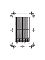
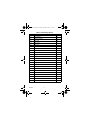
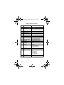
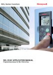
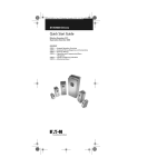
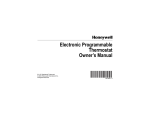
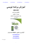
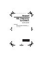
63-2610.fm Page 1 Thursday, January 30, 2003 1:31 PM
NXL Frequency
Converters
QUICK GUIDE
IMPORTANT
Before commissioning read the safety
instructions in chapter 1 of the User's Manual
(form 63-2599).
63-2610
63-2610
2
STOP
STOP
STOP
STOP
STOP
STOP
STOP
READY
I/O term
READY
I/O term
READY
I/O term
READY
I/O term
READY
I/O term
READY
I/O term
READY
I/O term
Monitoring menu
Parameter menu
Keypad control menu
Active faults menu
Fault history menu
System menu
STOP
Expander boards menu
READY
I/O term
STOP
I/O term
READY
P3.1 = Control Place Selection:
1 = I/O Terminals
2 = Keypad
3 = Field bus
R3.2 = Keypad Reference
P3.3 = Keypad Direction:
0 = Forward
1 = Reverse
P3.4 = Stop Button Activation
0 = Limited Function
1 = Always Enabled
R3.5 = PID Reference 1
R3.6 = PID Reference 2
M20960
63-2610.fm Page 2 Thursday, January 30, 2003 1:31 PM
mA
3
AO1–
RS 485
RS 485
RO1
RO1
19
A
B
21
22
RO1
AO1+
23
GND
DIN1
8
18
GND
7
11
+24V
6
DIN3
AI2–
5
10
AI2+
4
DIN2
AI1–
3
9
AI1+
2
SIGNAL
DESCRIPTION
Contact closed = start reverse
Contact closed = start forward
Ground for reference and controls
Voltage for switches, etc. max 0.1A
Current input frequency reference (programmable)
Ground for reference and controls
Voltage input frequency reference. Can be programmed as DIN4
Voltage for potentiometer, etc.
Relay output 1 FAULT
Serial bus
Serial bus
Output frequency Analog output
I/O ground
Programmable
Termination resistor 0/4 to 20 mA
Termination resistor 0/4 to 20 mA
M20959
Programmable Range 0 to wo mA/RL, max. 500 ohms
Ground for reference and controls
Multi-step speed selection 1 (programmable) Contact closed = Multi-step speed
Start reverse (programmable)
Start forward (programmable)
I/O ground
Control voltage output
Analog input,
current range 0/4 to 20 mA
I/O ground
Analog input, voltage range 0-10 Vdc.
+10Vref Reference output
TERMINAL
1
63-2610.fm Page 3 Thursday, January 30, 2003 1:31 PM
63-2610
63-2610.fm Page 4 Thursday, January 30, 2003 1:31 PM
Table 1. Monitoring Values.
Code
Signal name
Unit
V1.1
Output frequency
Hz
V1.2
Frequency reference
Hz
V1.3
Motor speed
rpm
V1.4
Motor current
A
V1.5
Motor torque
%
V1.6
Motor power
%
V1.7
Motor voltage
V
V1.8
DC-link voltage
V
V1.9
Unit temperature
ºC
V1.10
Analog input 1
V
V1.11
Analog input 2
mA
V1.12
Analog output current
mA
V1.13
Analog output current 1, expander board
mA
V1.14
Analog output current 2, expander board
mA
V1.15
DIN1, DIN2, DIN3
—
V1.16
DIE1, DIE2, DIE3
—
V1.17
RO1
—
V1.18
ROE1, ROE2, ROE3
—
V1.19
DOE 1
—
V1.20
PID Reference
%
V1.21
PID Actual value
%
V1.22
PID Error value
%
V1.23
PID Output
%
63-2610
4
63-2610.fm Page 5 Thursday, January 30, 2003 1:31 PM
Table 2. Faults and Fault Codes.
Code
1
2
3
5
6
8
9
10
11
13
14
15
16
17
22, 23
25
29
34
37
38
39
40
41
42
50
Fault
Overcurrent
Overvoltage
Earth fault
Charging switch
Emergency stop
System fault
Undervoltage
Input line supervision
Output phase supervision
Frequency converter under-temperature
Frequency converter overtemperature
Motor stalled
Motor overtemperature
Motor underload
EEPROM checksum fault
Microprocessor watchdog fault
Thermistor fault
Internal bus communication
Device change
Device added
Device removed
Device unknown
IGBT temperature
Brake resistor
Analog input Iin < 4 mA (selected signal range 4 to 20 mA)
51
52
53
54
External fault
Keypad communi-cation fault
Fieldbus fault
Slot fault
5
63-2610
63-2610.fm Page 6 Thursday, January 30, 2003 1:31 PM
Table 3. Basic Parameters.
Code
Parameter
P2.1.1
Min frequency
P2.1.2
Max frequency
P2.1.3
Acceleration time 1
Note
NOTE: If fmax > than the motor synchronous
speed, check suitability for motor and drive
system
P2.1.4
Deceleration time 1
P2.1.5
Current limit
P2.1.6
Nominal motor voltage
Check the rating plate of the motor
P2.1.7
Nominal motor frequency
Check the rating plate of the motor
P2.1.8
Nominal motor speed
The default applies for a 4-pole motor and a
nominal size frequency converter.
P2.1.9
Nominal motor current
Output current limit [A] of the unit
Check the rating plate of the motor
P2.1.10 Motor cosϕ
Check the rating plate of the motor
P2.1.11 Start function
0=Ramp
1=Flying start
P2.1.12 Stop function
0=Coasting
1=Ramp
2=Ramp+Run enable coast
3=Coast+Run enable ramp
P2.1.13 U/f optimisation
0=Not used
1=Automatic torque boost
P2.1.14 I/O reference
0=AI1
1=AI2
2=Keypad reference
3=Fieldbus reference
(FBSpeedReference)
4=Motor potentiometer
P2.1.15 AI2 signal range
1=0 mA to 20 mA
2=4 mA to 20 mA
63-2610
6
63-2610.fm Page 7 Thursday, January 30, 2003 1:31 PM
Table 3. Basic Parameters. (Continued)
Code
Parameter
Note
P2.1.16 Analog output function
0=Not used
1=Output freq. (0-fmax)
2=Freq. reference (0-fmax)
3=Motor speed (0-Motor nom. spd)
4=Output current (0-InMotor)
5=Motor torque (0-TnMotor)
6=Motor power (0-PnMotor)
7=Motor voltage (0--UnMotor)
8=DC-link volt (0-UnMotor)
9=PI controller ref. value
10=PI contr. act. value 1
11=PI contr. error value
12=PI controller output
P2.1.17 DIN2 function
0=Not used
1=Start Reverse
2=Reverse
3=Stop pulse
4=External fault, cc
5=External fault, oc
6=Run enable
7=Preset speed 2
8= Motor pot. UP (cc)
9= Disable PID (Direct freq. ref.)
P2.1.18 DIN3 function
0=Not used
1=Reverse
2=External fault, cc
3=External fault, oc
4=Fault reset
5=Run enable
6=Preset speed 1
7=Preset speed 2
8=DC-braking command
9=Motor pot. UP (cc)
10=Motor pot. DOWN (cc)
11=Disable PID (PID control selection)
12=PID Keypad ref. 2 selection
7
63-2610
63-2610.fm Page 8 Thursday, January 30, 2003 1:31 PM
Table 3. Basic Parameters. (Continued)
Code
Parameter
Note
P2.1.19 Preset speed 1
P2.1.20 Preset speed 2
P2.1.21 Automatic restart
0=Not used
1=Used
P2.1.22 Parameter conceal
0=All parameters visible
1=Only group b21 visible
By using this Honeywell literature, you agree that Honeywell will have no liability for any
damages arising out of your use or modification to, the literature. You will defend and
indemnify Honeywell, its affiliates and subsidiaries, from and against any liability, cost,
or damages, including attorneys’ fees, arising out of, or resulting from, any modification
to the literature by you.
Automation and Control Solutions
Honeywell International Inc.
1985 Douglas Drive North
Golden Valley, MN 55422
Honeywell Limited-Honeywell Limitée
35 Dynamic Drive
Scarborough, Ontario
M1V 4Z9
Printed in U.S.A. on recycled
paper containing at least 10%
post-consumer paper fibers.
63-2610 B.B. 2-03
Copyright © 2003 Honeywell International Inc.
All Rights Reserved
www.honeywell.com