1
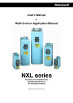
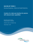
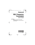
MN04003009E.fm Page 0 Wednesday, November 9, 2011 8:47 AM
SVX9000 Drives
Quick Start Guide
Effective November 2011
Supersedes December 2003
CONTENT
STEP 1 — Keypad Operation Overview
STEP 2 — Standard Wiring Diagrams and Connections
STEP 3 — Start-Up Wizard
STEP 4 — Operating and Programming Menu
Navigation
STEP 5 — Faults and Warning Indication
STEP 6 — Monitoring Menu
MN04003009E.fm Page 1 Wednesday, November 9, 2011 8:47 AM
STEP 1
Keypad Operation Overview
Keypad and Display
LCD Status Indicators
Indicator
Description
Run
Indicates that the SVX9000 is running and controlling the load. Blinks
when a stop command has been given but the SVX9000 is still
ramping down.
Counterclockwise Operation
The output phase rotation is BAC, corresponding to counterclockwise
rotation of most motors.
Clockwise Operation
The output phase rotation is ABC, corresponding to clockwise rotation
of most motors.
Stop
Indicates that the SVX9000 is stopped and not controlling the load.
Ready
Indicates that the SVX9000 is ready to be started.
Alarm
Indicates that there is one or more active drive alarm(s).
Fault
Indicates that there is one or more active drive fault(s).
I/O Terminal
Indicates that the I/O terminals have been chosen for control.
Keypad
Indicates that the keypad has been chosen for control.
Bus/Communications
Indicates that the communications bus control has been chosen for
control.
LED Status Indicators
Indicator
Description
local
Local — Steady Illumination
Indicates that the SVX9000 is ready to be started and operated from
the Local mode.
Local — Flashing
Indicates that the SVX9000 is ready for operating command to select
Local or Remote operation.
remote
Remote
Indicates that the SVX9000 is operating and controlling the load
remotely.
Remote — Flashing
Indicates that the SVX9000 is ready for operating command to select
Local or Remote operation.
fault
Fault
Indicates that there is one or more active drive fault(s).
1
SVX9000 Drives MN04003009E—November 2011 www.eaton.com
MN04003009E.fm Page 2 Wednesday, November 9, 2011 8:47 AM
STEP 1 (Continued)
Navigation Buttons
Button
Description
Start
This button operates as the START button for normal operation when
the “Keypad” is selected as the active control.
Enter
This button is used in the parameter edit mode to save the parameter
setting and move to the next parameter …
• to reset the Fault History if pressed while in the “Fault History”
menu.
• to confirm the acceptance of a change.
• to change a virtual button status while in the “Button” menu.
• to confirm the start-up list at the end of the Start-Up Wizard.
• when the “Operate” menu is active, to exit the “Operate” submenu.
Stop
This button has two integrated operations. The button operates as
STOP button during normal operation …
• motor STOP from the keypad, which is always active unless
disabled by the “StopButtonActive” parameter.
• used to reset the active faults.
Reset
Resets the active faults.
Local / Remote
Switches between LOCAL and REMOTE control for start, speed
reference and reverse functions. The control locations corresponding
to local and remote can be selected within an application.
Left Arrow
•
•
•
•
•
navigation button, movement to left.
in parameter edit mode, exits mode, backs up one step.
cancels edited parameter (exit from a parameter edit mode).
When in “Operate” menu will move backward through menu.
At end of “Start-Up Wizard”, repeats the “Start-Up Wizard”
setup menu.
Right Arrow
•
•
•
•
navigation button, movement to right.
enter parameter group mode.
enter parameter mode from group mode.
When in “Operate” menu will move forward through menu.
Up and Down Arrows
• move either up or down a menu list to select the desired menu item.
• editing a parameter/password, while the active digit/character is
scrolled.
• increase/decrease the reference value of the selected parameter.
• in the “Operate” menu, will cause the display of the active reference
source and value and allow its change if the keypad is the active
reference source. Used to set the password (if defined) when
leaving the “Operate” menu.
• scroll through the “Active Faults” menu when the SVX9000 is
stopped.
Menu Navigation
Navigation Tips
To navigate within one level of a menu, use the up and down arrows.
To move deeper into the menu structure and back out, use the right
and left arrows.
To edit a parameter, navigate to show that parameter’s value, and press
the right arrow button to enter the edit mode. In edit mode, the
parameter value will flash.
SVX9000 Drives MN04003009E—November 2011 www.eaton.com
2
MN04003009E.fm Page 3 Wednesday, November 9, 2011 8:47 AM
STEP 1 (Continued)
When in edit mode, the parameter value can be changed by pressing
the up or down arrow keys.
When in edit mode, pressing the right arrow a second time will allow
you to edit the parameter value digit by digit.
To confirm the parameter change you must press the ENTER button.
The value will not change unless the ENTER button is pushed.
Some parameters can not be changed while the SVX9000 is running.
The screen will display LOCKED if you attempt to edit these parameters
while the drive is running. Stop the drive to edit these parameters. See
the SVX9000 Application Manual for identification of these parameters
specific to your chosen application.
Main Menu
The data on the control keypad are arranged in menus and submenus. The
first menu level consists of M1 to M8 and is called the Main Menu. The Main
Menu is illustrated on Page 7. Some of the submenus will vary for each
application choice.
STEP 2
Standard Wiring Diagrams and Terminal Locations
Power and Motor Wiring Terminal Schematic for SVX9000 Drives
Power
Board
230V
480V
1 – 15 hp
1-1/2 – 30 hp
Control
Board
L1
L2
L3
B-
BR
U
V
W
B+ R-
T1
T2
T3
BR
(Optional)
External
RFI-Filter
(Optional)
L1
External
Filter
(Optional)
L2 L3
M
3~
SVX9000 Power and Motor Wiring for Low Horsepower Drives (1 – 30 hp)
3
SVX9000 Drives MN04003009E—November 2011 www.eaton.com
MN04003009E.fm Page 4 Wednesday, November 9, 2011 8:47 AM
STEP 2 (Continued)
Power
Board
230V
480V
20 – 30 hp
40 – 250 hp
Control
Board
L1
L2
L3
B-
BR
U
V
W
B+ R-
T1
T2
T3
BR
(Optional)
External
RFI-Filter
(Optional)
L1
External
Filter
(Optional)
L2 L3
M
3~
SVX9000 Power and Motor Wiring for
Large Horsepower Drives (20 – 250 hp)
SVX9000 Drives MN04003009E—November 2011 www.eaton.com
4
MN04003009E.fm Page 5 Wednesday, November 9, 2011 8:47 AM
STEP 2 (Continued)
Standard Application Default I/O Configuration
Reference
potentiometer
1 – 10 kW
mA
Terminal
Signal
Description
OPTA1
1
+10Vref Reference output
Voltage for potentiometer,
etc.
2
AI1+
Analog input,
voltage range
0 – 10V DC
Voltage input frequency
reference
3
AI1-
I/O Ground
Ground for reference and
controls
Analog input,
current range
0 – 20 mA
Current input frequency
reference
4
AI2+
5
AI2-
6
+24V
Control voltage
output
Voltage for switches, etc.
max 0.1A
7
GND
I/O ground
Ground for reference and
controls
8
DIN1
Start forward
(programmable)
Contact closed = start forward
9
DIN2
Start reverse
(programmable)
Contact closed = start reverse
10
DIN3
External
fault input
(programmable)
Contact open = no fault
Contact closed = fault
11
CMA
Common for DIN1 Connect to GND or +24V
– DIN3
12
+24V
Control voltage
output
Voltage for switches (see #6)
13
GND
I/O ground
Ground for reference and
controls
14
DIN4
Multi-step speed
select 1
DIN4
DIN5
Frequency
ref.
15
DIN5
Multi-step speed
select 2
Open
Closed
Open
Open
Open
Closed
Closed
Closed
Ref.Uin
Multi-step
ref.1
Multi-step
ref.2
Ref.Iin
16
DIN6
Fault reset
17
CMB
Common for DIN4 Connect to GND or +24V
– DIN6
18
AO1+
19
AO1-
Output frequency
Analog output
Programmable
Range 0 – 20 mA/RL,
max. 500W
20
DO1
Digital output
READY
Programmable
Open collector, I ≤ 50 mA,
U ≤ 48V DC
READY
Contact open = no action
Contact closed = fault reset
OPTA2
RUN
220V
AC
21
RO1
22
RO1
23
RO1
24
RO2
25
RO2
26
RO2
Relay
output 1
RUN
Relay
output 2
FAULT
Note: For more information on jumper selections, see the
9000X AF Drives User Manual, Chapter 4.
Jumper Block X3:
CMA and CMB Grounding
CMB connected to GND
CMA connected to GND
CMB isolated from GND
CMA isolated from GND
CMB and CMA internally connected
together, isolated from GND
= Factory default.
5
SVX9000 Drives MN04003009E—November 2011 www.eaton.com
MN04003009E.fm Page 6 Wednesday, November 9, 2011 8:47 AM
STEP 3
Start-Up Wizard
If the wizard is not enabled at power-up, press the STOP button for 5 secs.
to enable it.
Startup Wizard
“Press Enter”
Language
“English”
Application
“Standard”
3 – 5 Seconds Wait
Setup Starts
“Press Enter”
Min. Freq
“0.00” Hz
Max. Freq
“60.00” Hz
Accel. Time 1
“3.0” s
Decel Time 1
“3.0” s
Current Limit
“3.30” A
Motor NP Volt
“460” V
Motor NP Freq
“60.00” Hz
Motor NP Speed
“1720” rpm
Motor NP Current
“2.20” A
Power Factor
“0.85”
Loc. Ctrl. Place
“Keypad”
Rem. Ctrl. Place
“I/O Terminal”
Local Reference
“Keypad”
Remote Reference
“AI1”
Input Phase Supv
“Fault, Coast”
Repeat Setup?
<No
Yes>
Setup Done
Press Enter
Copy Parameters
<No
Yes>
Up to Keypad
<No
Yes>
Up to Keypad
Wait
Output Frequency
“0.00” Hz
SVX9000 Drives MN04003009E—November 2011 www.eaton.com
6
MN04003009E.fm Page 7 Wednesday, November 9, 2011 8:47 AM
STEP 4
Operating & Programming Menu Navitation
Main Menu
The data on the control keypad are arranged in menus and submenus. The
first menu level consists of M1 to M8 and is called the Main Menu. The
structure of these menus and their submenus is illustrated below. Some of
the submenus will vary for each application choice.
Main Menu Navigation
+ M1 Parameters
G1.1
...
G1.x
+ M2 Keypad Control
R2.1 Keypad Reference
P2.2 Keypad Direction
...
P2.x Stop Button Active
+ M3 Active Faults
Menu Navigation:
Up Arrow — The up arrow
advances to the next
menu item.
For example, pressing the
up arrow once will
advance from M1 to M2.
Down Arrow — The down
arrow backs up to the
previous menu item.
For example, pressing the
down arrow once will back
up from M2 to M1.
Right Arrow — The right
arrow will advance to the
next level in the menu.
For example, pressing the
right arrow once will
advance from M2 to R2.1.
Left Arrow — The left
arrow will back up one
level in the menu
structure.
For example, pressing the
left arrow once will back
up from R2.1 to M2.
A3.1 Active Fault 1
T3.1.1 Operation Days
...
T3.1.13 Zero Speed
...
A3.x Active Fault x
+ M4 Fault History
H4.1 Most Recent Fault
T4.1.1 Operation Days
...
T4.1.13 Zero Speed
...
H4.1.x Oldest Saved Fault
+ M5 System Menu
S5.1
S5.2
S5.3
S5.4
S5.5
S5.6
S5.7
S5.8
Language
Application
Copy Parameters
Compare Parameters
Security
Keypad Settings
Hardware Settings
System Information
+ M6 Expander Boards
G6.1 Slot A Board
...
G6.5 Slot E Board
+ M7 Monitor
V7.1 Output Frequency–0.00 Hz
V7.2 Frequency Reference–0.00 Hz
...
M7.1x Multimonitor
N7.1x.1
+ M8 Operate Mode
O1 Output Frequency–0.0 Hz
O2 Freq Reference–0.0 Hz
...
Ox . . .
Note:
7
Enter Key — Holding the “Enter” key for more than 3 seconds will
allow you to go directly to the programming mode.
SVX9000 Drives MN04003009E—November 2011 www.eaton.com
MN04003009E.fm Page 8 Wednesday, November 9, 2011 8:47 AM
STEP 4 (Continued)
Operate Menu — M8
The Operate Menu provides a easy to use method of viewing key numerical
Monitoring Menu items. Some applications also support the setting of
reference values in this menu. The items displayed vary by application. The
table below is an example for the Standard application.
Operate Menu Items — Standard Application Example
Code Signal Name
Unit Description
O.1
O.2
O.3
O.4
O.5
Output Frequency
FreqReference
Motor Speed
Motor Current
Motor Torque
Hz
Hz
rpm
A
%
O.6
Motor Power
%
O.7
O.8
O.9
O.10
Motor Voltage
DC-Bus Voltage
Unit Temperature
MotorTemperature
V
V
°C
%
R1
Keypad Reference
Hz
Output frequency
Frequency reference
Calculated motor speed
Measured motor current
Calculated torque based on nominal motor
torque
Calculated power based on nominal motor
power
Calculated motor voltage
Measured DC-bus voltage
Heatsink temperature
Calculated motor temperature based on the
motor nameplate information and the
calculated motor load
Keypad frequency reference setting
The menu is navigated by using the left and right arrow buttons. If a
reference level is available for setting, the up and down arrow buttons adjust
the value. To exit the Operate Menu to access the other menus, depress the
ENTER button for 2 seconds. While in the other menus, if there is no keypad
activity, the display will return to the Operate Menu after 30 seconds.
SVX9000 Drives MN04003009E—November 2011 www.eaton.com
8
MN04003009E.fm Page 9 Wednesday, November 9, 2011 8:47 AM
STEP 4 (Continued)
Parameters — M1
Standard Parameters — M1
Code
Parameter
Min.
Max.
P1.1.1
Min
frequency
Max
frequency
0.00
Par.
Hz
1.1.2
320.00 Hz
0.00
101
60.00
0.1
3000.0 s
3.0
102 NOTE: If fmax >
than the motor
synchronous
speed, check
suitability for
motor and drive
system.
103
0.1
3000.0 s
3.0
104
A
IL
107
V
110
30.00 320.00 Hz
P: 230V
P: 460V
P: 575V
60.00
300
1720
P1.1.2
P1.1.3
P1.1.4
P1.1.5
P1.1.6
P1.1.7
P1.1.8
Acceleration
time 1
Deceleration
time 1
Current limit
Nominal
voltage of
the motor
Nominal
frequency of
the motor
Nominal
speed of the
motor
Par.
1.1.1
0.1 x 2 x IH
IH
180
690
Unit Default Cust ID
20 000 rpm
P1.1.9
Nominal
0.1 x 2 x IH
current of the IH
motor
P1.1.10 Power Factor 0.30 1.00
A
IH
0.85
P1.1.11 Local Control 1
Place
3
2
P1.1.12 Remote
Control
Place
P1.1.13 Local
reference
1
3
1
0
3
2
0
3
0
P1.1.15 Identification 0
2
0
P1.1.16 V/Hz Opt
0
1
0
P1.1.17 Preset
speed 1
P1.1.18 Preset
speed 2
0.00
Par.
1.1.2
Par.
1.1.2
P1.1.14 Remote
reference
9
0.00
Hz
10.00
Hz
40.00
Note
111 Check the rating
plate of the
motor.
112 The default applies
for a 4-pole motor
and a nominal
size frequency
converter.
113 Check the rating
plate of the
motor.
120 Check the rating
plate of the
motor.
171 1 = I/O Terminal
2 = Keypad
3 = Fieldbus
172 1 = I/O Terminal
2 = Keypad
3 = Fieldbus
173 0 = AI1
1 = AI2
2 = Keypad
3 = Fieldbus
174 0 = AI1
1 = AI2
2 = Keypad
3 = Fieldbus
631 0 = Not used
1 = V/Hz
2 = V/Hz with
boost
109 0 = Not used
1 = Automatic
torque boost
105 Speeds preset by
operator.
106
Parameter value can only be changed after the drive has been stopped.
SVX9000 Drives MN04003009E—November 2011 www.eaton.com
MN04003009E.fm Page 10 Wednesday, November 9, 2011 8:47 AM
STEP 4 (Continued)
Input Signals — M1 ➔ G1.2
Code
Parameter Min. Max.
P1.2.1 Start/Stop 0
logic
Unit Default Cust ID
6
0
P1.2.2 DIN3
function
0
7
1
P1.2.3 Current
reference
offset
P1.2.4 Reference
scaling
minimum
value
P1.2.5 Reference
scaling
maximum
value
P1.2.6 Reference
inversion
P1.2.7 Reference
filter time
P1.2.8 AI1 signal
selection
P1.2.9 AI2 signal
selection
0
1
1
0.00 Par.
1.2.5
Hz
0.00
0.00 320.00 Hz
0.00
0
0
1
0.00 10.00
s
0.10
A.1
A.2
300
Note
DIN1
0 Start fwd
1 Start/Stop
2 Start/Stop
DIN2
Start rvs
Rvs/Fwd
Run
enable
Stop
pulse
Rvs Rvs/
Fwd
Run
enable
3 Start
pulse
4 Fwd 5 Start /
Stop
6 Start /
Stop
301 0 = Not used
1 = Ext. fault. closing
cont.
2 = Ext. fault. opening
cont.
3 = Run enable
4 = Acc./Dec. time select.
5 = Force CP to
Remote 6 = Rvs (if par. 1.2.1 = 3)
302 0 = 0 – 20mA
1 = 4 – 20mA
303 Selects the frequency
that corresponds to the
min. reference signal
0.00 = No scaling
304 Selects the frequency
that corresponds to the
max. reference signal
0.00 = No scaling
305 0 = Not inverted
1 = Inverted
306 0 = No filtering
377 TTF programming
method used.
388 TTF programming
method used.
Parameter value can only be changed after the drive has been stopped.
Use TTF method to program these parameters.
Rising edge required to start.
CP = control place.
Output Signals — M1 ➔ G1.3
Code
Parameter Min. Max.
P1.3.1 Analog
output 1
signal
selection
P1.3.2 Analog
output
function
0
P1.3.3 Analog
output
filter time
0.00 10.00
0
Unit Default Cust ID
8
s
Note
A.1
464 TTF programming
method used.
1
307 0 = Not used
1 = Output freq.
(0 – fmax)
2 = Freq. reference
(0 – fmax)
3 = Motor speed
(0 – Motor nominal
speed)
4 = Motor current
(0 – InMotor)
5 = Motor torque
(0 – TnMotor)
6 = Motor power
(0 – PnMotor)
7 = Motor voltage
(0 – UnMotor)
8 = DC-Bus volt
(0 – 1000V)
308 0 = No filtering
1.00
Parameter value can only be changed after the drive has been stopped.
SVX9000 Drives MN04003009E—November 2011 www.eaton.com
10
MN04003009E.fm Page 11 Wednesday, November 9, 2011 8:47 AM
STEP 4 (Continued)
Output Signals — M1 ➔ G1.3 (Continued)
Code
Parameter
Min. Max.
P1.3.4
Analog output
inversion
Analog output
minimum
Analog output
scale
Digital output 1
function
0
1
0
0
1
0
10
1000
0
16
1
0
16
2
P1.3.5
P1.3.6
P1.3.7
P1.3.8
Relay output 1
function
P1.3.9 Relay output 2
function
P1.3.10 Output
frequency limit
1 supervision
P1.3.11 Output
frequency limit
1; Supervised
value
P1.3.12 Analog output
2 signal
selection
P1.3.13 Analog output
2 function
P1.3.14 Analog output
2 filter time
P1.3.15 Analog output
2 inversion
P1.3.16 Analog output
2 minimum
P1.3.17 Analog output
2 scaling
11
Unit Default Cust ID
%
100
0
16
3
0
2
0
0.00 320.00 Hz
0.00
0
0.1
0
8
0.00 10.00
4
s
1.00
0
1
0
0
1
0
10
1000
%
100
Note
309 0 = Not inverted
1 = Inverted
310 0 = 0 mA
1 = 4 mA
311
312 0 = Not used
1 = Ready
2 = Run
3 = Fault
4 = Fault inverted
5 = FC overheat
warning
6 = Ext. fault or
warning
7 = Ref. fault or
warning
8 = Warning
9 = Reversed
10 = Preset
speed 1
11 = At speed
12 = Mot.
regulator
active
13 = OP freq.
limit 1
superv.
14 = Remote
Control
Active
15 = Thermistor
fault/warng
16 = Fieldbus
input data
313 Same as
parameter 1.3.7
314 Same as
parameter 1.3.7
315 0 = No limit
1 = Low limit
supervision
2 = High limit
supervision
316
471 TTF
programming
method used.
472 Same as
parameter 1.3.2
473 0 = No filtering
474 0 = Not inverted
1 = Inverted
475 0 = 0 mA
1 = 4 mA
476
Parameter value can only be changed after the drive has been stopped.
SVX9000 Drives MN04003009E—November 2011 www.eaton.com
MN04003009E.fm Page 12 Wednesday, November 9, 2011 8:47 AM
STEP 4 (Continued)
Drive Control Parameters — M1 ➔ G1.4
Code
Parameter
Min. Max.
Unit Default Cust ID
P1.4.1
Ramp 1
shape
0.0
10.0
s
0.0
P1.4.2
Ramp 2
shape
0.0
10.0
s
0.0
P1.4.3
Acceleration
time 2
Deceleration
time 2
Brake
chopper
0.1
3000.0 s
0.1
3000.0 s
10.0
503
0
4
0
504 0 = Disabled
1 = Used when
running
2 = External brake
chopper
3 = Used when
stopped/
running
4 = Used when
running (no
testing)
505 0 = Ramp
1 = Flying start
506 0 = Coasting
1 = Ramp
2 = Ramp+Run
enable coast
3 = Coast+Run
enable ramp
P1.4.4
P1.4.5
10.0
P1.4.6
Start function 0
1
0
P1.4.7
Stop function 0
3
1
P1.4.8
DC braking
current
P1.4.9
DC braking
time at stop
P1.4.10 Frequency to
start DC
braking
during
ramp stop
P1.4.11 DC braking
time at start
P1.4.12 Flux brake
P1.4.13 Flux braking
current
0.00 IL
A
Note
500 0 = Linear
>0 = S-curve ramp
time
501 0 = Linear
>0 = S-curve ramp
time
502
0.7 x IH
507
0.00 600.00 s
0.00
0.10 10.00
1.50
508 0 = DC brake is off
at stop
515
Hz
0.00 600.00 s
0
1
0.1
x IH
IL
0.00
0
A
IH
516 0 = DC brake is off
at start
520 0 = Off
1 = On
519
Parameter value can only be changed after the drive has been stopped.
Prohibit Frequencies — M1 ➔ G1.5
Code
Parameter
P1.5.1
Skip frequency 0.00 Par.
range 1 low
1.5.2
limit
Skip frequency 0.00 Par.
range 1 high
1.1.2
limit
Skip frequency 0.1 10.0
acc./dec. ramp
P1.5.2
P1.5.3
Min. Max.
Unit Default Cust ID
Note
Hz
0.00
509
Hz
0.0
510 0 = Skip frequency
range 1 not
used
518
1.0
SVX9000 Drives MN04003009E—November 2011 www.eaton.com
12
MN04003009E.fm Page 13 Wednesday, November 9, 2011 8:47 AM
STEP 4 (Continued)
Motor Control Parameters — M1 ➔ G1.6
Code
Parameter
Min.
Max.
P1.6.1
Motor
control
mode
0
1/6
0
V/Hz
optimization
0
1
0
V/Hz ratio
selection
0
3
0
Field
weakening
point
Voltage at
field
weakening
point
V/Hz curve
midpoint
frequency
V/Hz curve
midpoint
voltage
Output
voltage at
zero
frequency
Switching
frequency
8.00
320.00 Hz
60.00
600 SVX:
0 = Frequency
control
1 = Speed control
Additionally for
SPX:
2 = Torque control
3 = Closed loop
speed ctrl
4 = Closed loop
torque ctrl
109 0 = Not used
1 = Automatic
torque boost
108 0 = Linear
1 = Squared
2 = Programmable
3 = Linear with
flux optim.
602
10.00 200.00 %
100.00
603 n% x Unmot
0.00
Par.
1.6.4
60.00
604
0.00
100.00 %
100.00
0.00
40.00
1.30
605 n% x Unmot
Parameter max.
value = par. 2.6.5
606 n% x Unmot
1.0
Varies kHz
Varies
0
2
1
P1.6.11 Undervoltage 0
controller
P1.6.12 Load
0.00
Drooping
1
1
100.00
0.00
P1.6.13 Identification
1
0
P1.6.2
P1.6.3
P1.6.4
P1.6.5
P1.6.6
P1.6.7
P1.6.8
P1.6.9
P1.6.10 Overvoltage
controller
0
Unit Default Cust ID
Hz
%
Note
601 See Table 8-12 on
page 57 for exact
values
607 0 = Not used
1 = Used (no
ramping)
2 = Used (ramping)
608 1 = Yes
2 = No
620 Drooping % of
nominal speed at
nominal torque
631 0 = Not used
1 = OL v/f Ratio
2 = OL v/f and
Boost
Parameter value can only be changed after the drive has been stopped.
Output Signals — M1 ➔ G1.3
Code
Parameter
Min.
Max.
P1.7.1
Response to
reference
fault
0
6
13
Unit Default Cust ID
6
Note
700 0 = No response
1 = Warning
2 = Warning+
Previous Freq.
3 = Wrng+
PresetFreq
1.7.2
4 = Fault.stop acc.
to 1.4.7
5 = Fault.stop by
coasting
6 = Fault, Restart
SVX9000 Drives MN04003009E—November 2011 www.eaton.com
MN04003009E.fm Page 14 Wednesday, November 9, 2011 8:47 AM
STEP 4 (Continued)
Protections — M1 ➔ G1.7
Code
Parameter
Min.
Max.
Unit Default Cust ID
P1.7.2
Reference fault
frequency
Response to
external fault
Input phase
supervision
Response to
undervoltage
fault
Output phase
supervision
Earth fault
protection
Thermal
protection of
the motor
Motor ambient
temperature
factor
Motor cooling
factor at zero
speed
Motor thermal
time constant
Motor duty
cycle
Stall protection
0.00
Hz
0
Par.
1.1.2
3
0
3
3
1
3
0
P1.7.3
P1.7.4
P1.7.5
P1.7.6
P1.7.7
P1.7.8
P1.7.9
P1.7.10
P1.7.11
P1.7.12
P1.7.13
P1.7.14 Stall current
Note
0.00
728
2
0
701 0 = No response
1 = Warning
Fault.stop
730 2 = acc.
to 1.4.7
3 = Fault.stop
727
by coasting
3
2
702
0
3
2
703
0
3
2
704
-100.0 100.0
%
0.0
705
0.0
150.0
%
40.0
706
1
200
min 45
707
0
100
%
100
708
0
3
0
0.1
InMotor A
x2
120.00 s
Par.
Hz
1.1.2
3
IL
709 0 = No response
1 = Warning
2 = Fault.stop
acc. to 1.4.7
3 = Fault.stop
by coasting
710
15.00
25.0
711
712
0
P1.7.15 Stall time limit 1.00
P1.7.16 Stall frequency 1.0
limit
P1.7.17 Underload
0
protection
P1.7.18 Field
weakening area
load
P1.7.19 Zero frequency
load
P1.7.20 Underload
protection time
limit
P1.7.21 Response to
thermistor fault
10
150
%
50
713 0 = No response
1 = Warning
2 = Fault.stop
acc. to 1.4.7
3 = Fault.stop
by coasting
714
5.0
150.0
%
10.0
715
2
600
s
20
716
0
3
2
P1.7.22 Response to
fieldbus fault
P1.7.23 Response to
slot fault
P1.7.24 FB MCW Bit 15
0
3
2
732 0 = No response
1 = Warning
2 = Fault.stop
acc. to 1.4.7
3 = Fault.stop
by coasting
733 See P1.7.21
0
3
2
734 See P1.7.21
0
2
0
771 0 = No action
1 = Fault low
2 = Fault high
SVX9000 Drives MN04003009E—November 2011 www.eaton.com
14
MN04003009E.fm Page 15 Wednesday, November 9, 2011 8:47 AM
STEP 4 (Continued)
Auto Restart Parameters — M1 ➔ G1.8
Code
Parameter
Min.
Max.
Unit Default Cust ID
P1.8.1
P1.8.2
P1.8.3
Wait time
Trial time
Start function
0.10
0.00
0
10.00
60.00
2
s
s
0
10
0
717
718
719 0 = Ramp
1 = Flying start
2 = According to
par. 1.4.6
720
0
10
0
721
0
3
0
722
0
10
0
723
0
10
0
726
0
10
0
725
0
10
0
738
P1.8.4
Number of tries
after
undervoltage
trip
P1.8.5 Number of tries
after
overvoltage
trip
P1.8.6 Number of tries
after
overcurrent trip
P1.8.7 Number of tries
after reference
trip
P1.8.8 Number of tries
after motor
temperature
fault trip
P1.8.9 Number of tries
after external
fault trip
P1.8.10 Number of tries
after underload
fault trip
0.50
30.00
0
Note
Keypad Control — M2
This menu provides the parameters for the setting of the keypad frequency
reference, the selection of motor direction when in keypad operation, and
when the STOP button is active.
Keypad Control Parameters — M2
Code Parameter
Min.
Max.
P2.1
Control place
0
3
R2.1
Keypad
reference
Direction (on
keypad)
Stop button
Par.
1.1.1
0
Par.
1.1.2
1
0
1
1
Operate menu
hide
0
1
0
P2.3
P2.4
P2.5
Unit Default Cust ID
Note
0
1685 0 = Keypad L/R
1 = Local
2 = Remote
3 = I/O force
0
123
Hz
0 = Forward
1 = Reverse
114 0 = Limited
function of
Stop button
1 = Stop button
always
enabled
1688 0 = No
1 = Yes
Other Menus — M3 to M6
Menus M3 to M6 provide information on the Active Faults, Fault History,
System Menu settings and the Expander Board setup. These menu items are
explained in detail in Chapter 5 of the SVX9000 User Manual.
15
SVX9000 Drives MN04003009E—November 2011 www.eaton.com
MN04003009E.fm Page 16 Wednesday, November 9, 2011 8:47 AM
STEP 5
Faults and Fault Codes
Code/Fault Directory
Fault
Code Fault
Fault
Code Fault
Fault
Code Fault
1
Overcurrent
16
Motor
overtemperature
40
Device unknown
2
3
Overvoltage
Ground (Earth)
Fault
17
22
Motor underload
EEPROM
checksum fault
41
42
IGBT temperature
Brake resistor
overtemperature
5
6
Charging Switch
Emergency stop
24
25
Counter fault
Microprocessor
watchdog fault
43
44
Encoder fault
Device change
(different type)
7
Saturation trip
26
Startup prevented
45
8
System fault
29
Thermistor fault
50
9
Undervoltage
31
IGBT temperature
(hardware)
51
Device added
(different type)
Analog input Iin
< 4 mA (for the
signal range 4 to
20 mA)
External fault
10
Input line
supervision
32
Fan heat sink
52
11
Output phase
supervision
Brake chopper
supervision
34
CAN bus
communication
Control unit
53
13
SVX9000
undertemperature
37
Device change
(same type)
56
PT100 board
temperature fault
14
SVX9000
overtemperature
38
—
—
15
Motor stalled
39
Device added
(same type)
Device removed
—
—
12
36
54
Keypad
communication
fault
Communication
bus fault
Slot fault
SVX9000 Drives MN04003009E—November 2011 www.eaton.com
16
MN04003009E.fm Page 17 Wednesday, November 9, 2011 8:47 AM
STEP 6
Monitoring Menu — M7
The Monitoring Menu items are meant for viewing parameter values during
operation. Monitored values are updated every 0.3 sec. Monitored items are
identified by item numbers V7.1 to V1.xx, where “xx” varies by application.
The table below provides an example of the monitored values for the
Standard application.
Monitored parameters are not editable from this menu (See Parameter
Menu [M1] to change parameter values).
Monitoring Menu Items — Standard Application Example
Code Signal Name
Unit Description
V7.1
Output
Frequency
V7.2
Frequency
reference
V7.3
Motor speed
V7.4
Motor current
V7.5
Motor torque
V7.6
Motor power
V7.7
Motor voltage
V7.8
DC bus voltage
V7.9
Unit temperature
V7.10 Calculated motor
temperature
Hz
Output frequency
Hz
Frequency reference setting
rpm
A
%
%
V
V
°C
°C
V7.11
V7.12
V7.13
V7.14
V7.15
V7.16
V7.17
V
mA
—
—
—
mA
Calculated motor speed
Measured motor current
Calculated torque based on nominal motor torque
Calculated power based on nominal motor power
Calculated motor voltage
Measured DC-bus voltage
Heatsink temperature
Calculated motor temperature based on the
motor nameplate information and the calculated
motor load
Voltage input at Terminals AI1+ and GND
Current input at Terminals AI2+ and AI2Digital input status (see figure below)
Digital input status (see figure below)
Digital and relay output status (see figure below)
Current output at Terminals AO1+ and AO1(See below)
Analog Input 1
Analog input 2
DIN1, DIN2, DIN3
DIN4, DIN5,DIN6
DO1, RO2, RO3
Analog Iout
Multimonitor
V1.13
DIN1, DIN2, DIN3
OFF ON OFF
Digital Inputs — DIN1, DIN2, DIN3 Status
V1.14
DIN4, DIN5, DIN6
ON OFF OFF
Digital Inputs — DIN4, DIN5, DIN6 Status
V1.15
DO1, RO1, RO2
OFF OFF ON
Digital and Relay Outputs — DO1, RO1, RO2 Status
Multimonitor (V7.17)
This parameter allows the viewing and selection (if allowed by System
menu item, P5.5.4) of three simultaneously monitored items from the
Monitored Menu Items shown in the table above. Use the right arrow key to
select the item to be modified and then the up or down arrow keys to select
the new item. Press the ENTER key to accept the change.
17
SVX9000 Drives MN04003009E—November 2011 www.eaton.com
MN04003009E.fm Page 18 Wednesday, November 9, 2011 8:47 AM
MN04003009E.fm Page 19 Wednesday, November 9, 2011 8:47 AM
Eaton is dedicated to ensuring that reliable, efficient
and safe power is available when it’s needed most.
With unparalleled knowledge of electrical power
management across industries, experts at Eaton
deliver customized, integrated solutions to solve our
customers’ most critical challenges.
Our focus is on delivering the right solution for the
application. But, decision makers demand more than
just innovative products. They turn to Eaton for an
unwavering commitment to personal support that
makes customer success a top priority. For more
information, visit www.eaton.com/electrical.
Eaton Corporation
Electrical Sector
1111 Superior Ave.
Cleveland, OH 44114
United States
877-ETN-CARE (877-386-2273)
Eaton.com
© 2011 Eaton Corporation
All Rights Reserved
Printed in USA
Publication No. MN04003009E / Z11191
November 2011
Eaton is a registered
trademark of Eaton
Corporation.
All other trademarks
are property of their
respective owners.