1
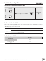
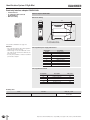
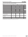
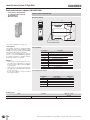
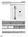
Identification System CIS3A-Mini Read/write interface adapter CIA3SX1R1G08 Serial interface RS232/RS422 In combination with read head CIT3ASX1N12ST DIN rail mounting Interface adapter CIA3SX1R1G08 Dimension drawing 114 22,50 H1 H2 LED+ LEDUB OV SH1 OUT 99 CIS3 STATE ACTIVE RXD TDX OV SH2 A B A1 B1 Suitable for 35 mm DIN rail acc. to DIN EN 60715 TH35 For possible combinations see page 33 Serial interface The individual commands for reading and writing the data carrier are in accordance with the common 3964R protocol and are described in the EUCHNER CIS3 system manual (order no. 084 727). For data carrier programming away from the system, a convenient WINDOWS®-compatible PC software application is available (Software Transponder Coding, see page 41). Attention: On the usage of a screened cable the connection cable for the serial interface is allowed to be max. 5 m long for RS232 and max. 1000 m long for RS422. On the usage of a screened cable the connection cable to the read/write head is allowed to be max. 15 m long. It is only ever possible to connect 1 read head per interface adapter. Pin assignment Designation 0V/GND Description Ground, DC 0 V 24 V/UB Power supply, DC 24 V TxD Serial interface transmit RxD Serial interface receive A/TxD+ Serial interface transmit + B/TxD- Serial interface transmit - A1/RxD+ Serial interface receive + RS232 RS422 B1/RxD- Serial interface receive - OUT Output data carrier active, 24 V SH2 Screen data wire Pin assignment read head Designation Description H1 Read head antenna Wire color BN H2 Read head antenna WH LED + Read head LED YE LED - Read head LED GN SH1 Read head screen BK Ordering table Series Interface Order no. / item Read/write interface adapter for CIS3A-Mini Serial RS232 / RS422 077 910 CIA3SX1R1G08 36 Subject to technical modifications; no responsibility is accepted for the accuracy of this information.